
| Sedj | Posted: 29 Jun 2022, 10:58 PM |
|---|---|
 Member Posts: 16 Joined: 29-June 22 |
Everything about the clock works perfectly..... All though i just looked at my clock today (like 2 days into it working just fine) and segment G on the first Digit is not working and I was just wanting to know if you think its the display that is faulty or something else?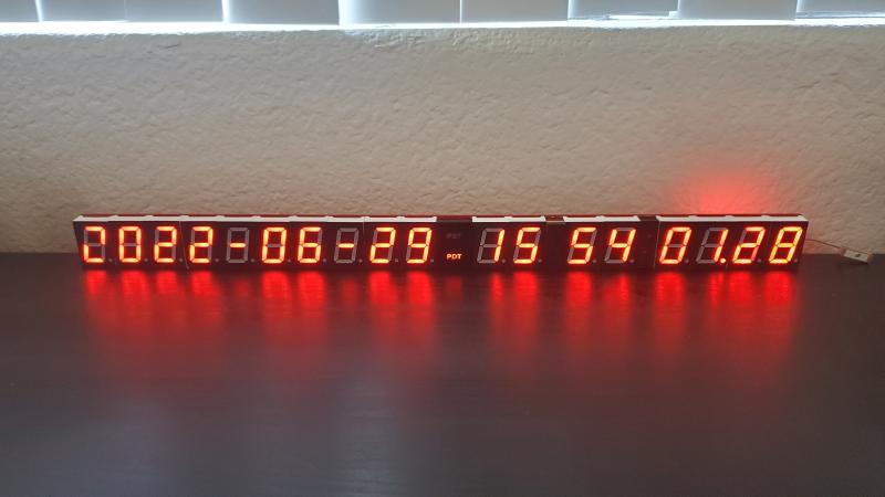 ------------- |
| [top] | |
| mit | Posted: 30 Jun 2022, 11:38 AM |
 yeah whatever Admin Posts: 687 Joined: 4-May 16 |
The quickest way to test this is to turn the clock off and use a multimeter in diode tester mode to see if the segment lights up. 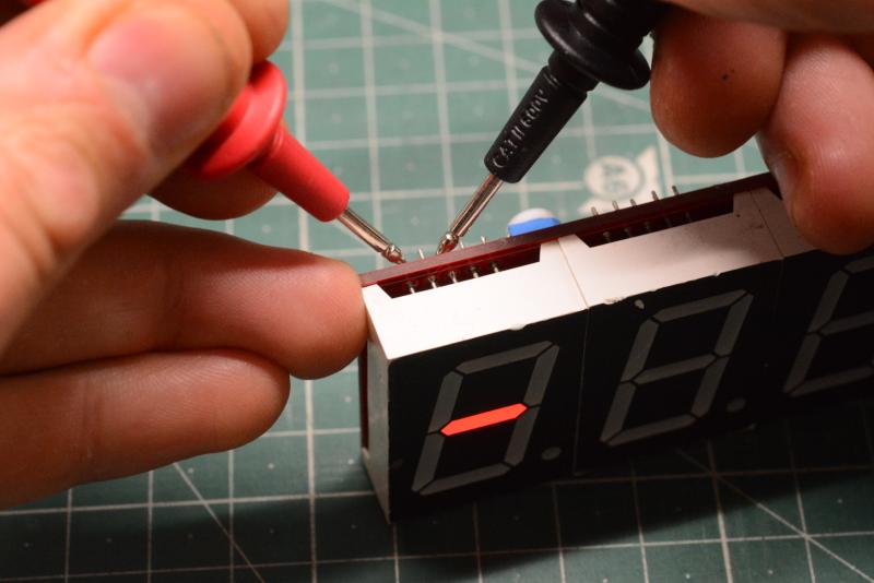 Also, I would try adjusting the brightness setting on the back of the clock. I have heard a few reports recently that turning the brightness down fixed various problems, most likely because the power supply was poorly filtered, and at high brightness the current draw was worsening the problem. If that does have an effect, adding a big electrolytic capacitor should help a lot (and maybe using a different power supply). ------------- |
| [top] | |
| Sedj | Posted: 1 Jul 2022, 01:37 AM |
|
Member Posts: 16 Joined: 29-June 22 |
I tested a few 7SD and none of them worked and then I read the spec sheet of my meter and found on page 5 on the link below the diode testing voltage is 1.5V (See link below this line) https://manualzz.com/doc/54160882/ames-64014-dm600-compact-digital-multimeter-owner-s-manual And on this link on page 14 is what i believe to be the display i have ( See link below this line) https://z9q5c2a5.stackpathcdn.com/wp-content/uploads/2018/10/10016AS.pdf I am just thinking my meter isnt suited for this application due to low test voltages? ------------- |
| [top] | |
| mit | Posted: 4 Jul 2022, 11:06 AM |
|
yeah whatever Admin Posts: 687 Joined: 4-May 16 |
You could instead try testing with a different power source. A 3V coin cell could work, or another battery of some kind, or a bench power supply. I would say to only touch the pins for a brief moment to make sure you don't send too much current through, or alternatively, use a resistor to limit the current. But make sure you are touching the right pins on the digit, the negative lead needs to be connected to the middle pin. ------------- |
| [top] | |
| Sedj | Posted: 13 Aug 2022, 12:28 AM |
|
Member Posts: 16 Joined: 29-June 22 |
Disregard the picture being upside down but why would after my clock working perfectly fine for a few weeks just be stuck like this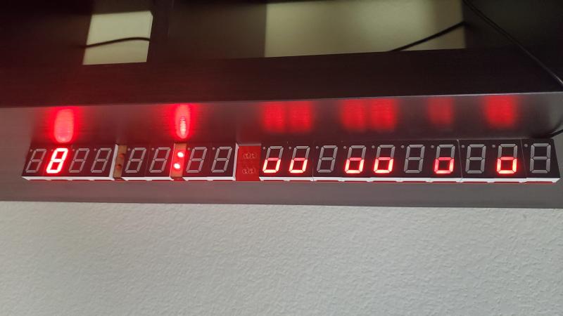 Last edit by Sedj at 13 Aug 2022, 12:29 AM ------------- |
| [top] | |
| mit | Posted: 13 Aug 2022, 10:28 AM |
|
yeah whatever Admin Posts: 687 Joined: 4-May 16 |
I've never seen anything like that. It looks like both display drivers have frozen part-way through their matrix. In fact the time side looks like it's frozen mid matrix, and the date side looks like something else has happened. Does it just show that when you power it on? Is it possible there was some kind of power surge? Can you try it with a different power source, and with the brightness knob turned down? ------------- |
| [top] | |
| Sedj | Posted: 13 Aug 2022, 05:51 PM |
|
Member Posts: 16 Joined: 29-June 22 |
Ive tried a few different power sources and changed the brightness and nothing seems to fix it..... :( probably fried because of a power surge ------------- |
| [top] | |
| mit | Posted: 13 Aug 2022, 07:03 PM |
|
yeah whatever Admin Posts: 687 Joined: 4-May 16 |
That sucks. Does it always show the same thing when you power it on? One thing you could try is to remove the ATtiny chip from its socket (carefully!) and power it on with no chip. If the display stays off completely, then it might be the ATtiny is damaged, but if it still shows that strange mess then it's probably the display drivers that are damaged. The ATtiny chip is at least a lot easier to replace, if that is the problem. ------------- |
| [top] | |
| Sedj | Posted: 16 Aug 2022, 08:39 AM |
|
Member Posts: 16 Joined: 29-June 22 |
So I tried that and its still displays the same issues.... not to sure if the other chips would get fried :| ------------- |
| [top] | |
| mit | Posted: 17 Aug 2022, 12:22 PM |
|
yeah whatever Admin Posts: 687 Joined: 4-May 16 |
That's really unfortunate. I've not heard of anything like it happening before. Usually the MAX7219 chips are really resilient. I'm not sure what to suggest really, you could try replacing them (I made a guide on how to replace them here) but there's a risk that other parts of the clock were damaged too. Does the GPS module still work - does the LED start blinking after it's had time to acquire a fix? ------------- |
| [top] | |
| Sedj | Posted: 18 Aug 2022, 07:53 AM |
|
Member Posts: 16 Joined: 29-June 22 |
Yeah the GPS is not aquiring signal at all ------------- |
| [top] | |
| Sedj | Posted: 20 Jun 2023, 12:37 AM |
|
Member Posts: 16 Joined: 29-June 22 |
Well I've finally gotten around to swapping out the MAX7219 chips and now I have no display so idk ill probably just buy another kit :( Don't know if I cooked something while replacing the chips but everything looks good around the board and replaced components The GPS still acquires signal and every display is dead Last edit by Sedj at 20 Jun 2023, 12:57 AM ------------- |
| [top] | |
| mit | Posted: 23 Jun 2023, 11:37 AM |
|
yeah whatever Admin Posts: 687 Joined: 4-May 16 |
Sorry to hear that. I can offer more help to try and debug it if you like. If it was an overvoltage thing, it might be helpful to look at this thread. It seems the max chips and the ATtiny chip needed replacing. I would also really recommend testing the digits somehow, just a power supply and a suitably sized resistor would be enough, or a coin cell (which can't provide enough current to damage it). ------------- |
| [top] | |
| Sedj | Posted: 23 Jun 2023, 11:28 PM |
|
Member Posts: 16 Joined: 29-June 22 |
So I have already replaced both with these which are suitable im sure of but they may be dead on arrival since it was displaying something before I swapped them :| So im going to try replacing the tiny and find some more 7219s Would you happen to have any guides/info for reprogramming the tinys? 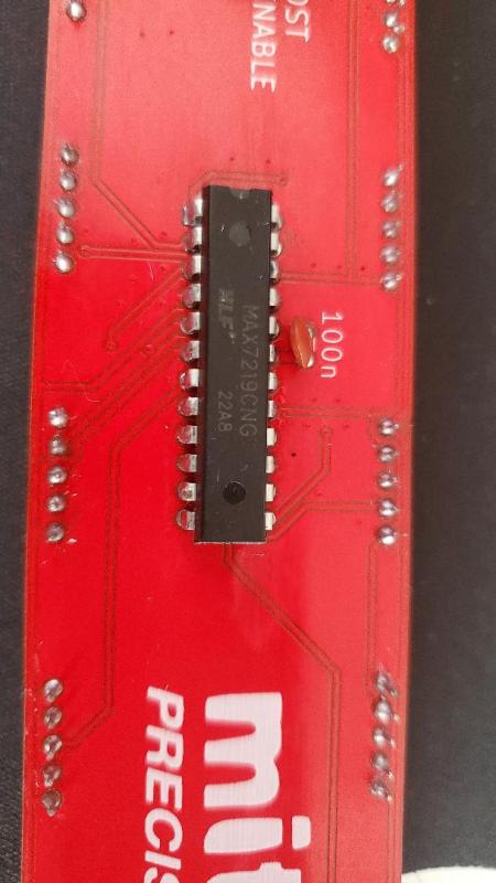 Last edit by Sedj at 23 Jun 2023, 11:51 PM ------------- |
| [top] | |
| mit | Posted: 24 Jun 2023, 06:08 PM |
|
yeah whatever Admin Posts: 687 Joined: 4-May 16 |
If the ATtiny is damaged, or the old MAX chips were damaged, that might explain why there's nothing on the display even if there was before. I'd wait and try the new ATtiny chip before re-soldering the max chips again, although yes it is possible they're dead on arrival as that has happened to me in the past. The way to flash a new ATtiny is almost identical to the instructions for changing the timezone, on the instructions page: https://mitxela.com/projects/precision_clock_mk_iii/assembly_instructions#change-timezone The only extra step is that you need to configure the fuse bytes to disable the DIV8 setting, which takes this avrdude command:
There is also potentially a further step to calibrate the oscillator, but I wouldn't bother looking into that until the rest of it's working. ------------- |
| [top] | |
Sign in to post a reply.