
Assembly Instructions
22 Apr 2019This is the instruction manual for assembling the Precision Clock Kit.
Click here for the lengthy writeup explaining how the clock was developed.
Contents
- Tools needed
- List of components in the kit
- Steps
- Troubleshooting
- How to change the timezone
- Optional Steps
These instructions follow exactly the same steps as the video I posted, but with a bit more annotated detail. In these pictures, the PCB has "Rev 3" printed on it. In February 2022, I started shipping boards marked "Rev 3b", these are identical except for a minor update to the barrel jack footprint.
Some general soldering advice:
- Press the soldering iron firmly against the joint before you start poking it with solder. You want the parts to be hot enough to melt the solder when it comes into contact with them, otherwise it won't wet the joint correctly.
- If you find that the solder isn't melting, it's usually a mistake to think that the iron isn't hot enough, it's almost always that the tip needs cleaning. I tend to solder at 300°C most of the time, using a lead-based solder. Lead-free solder needs a bit more heat but in general, using too high a temperature will cause more problems in the long run.
Tools needed
- a soldering iron
- solder
- super glue or something similar for attaching the laser-cut parts
- wire cutters
- tweezers or pliers
List of components in the kit
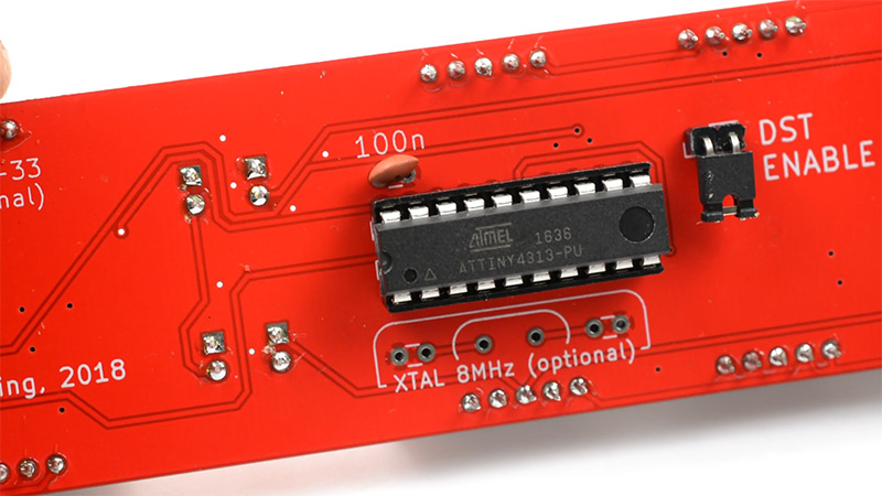
One ATtiny microcontroller (either an ATtiny2313, ATtiny2313A, or an ATtiny4313):
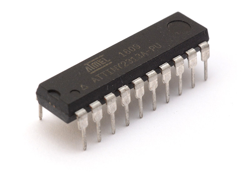
Note: if you are sourcing components from scratch, you will need to flash the ATtiny chip with the firmware and configure the fuse bytes.
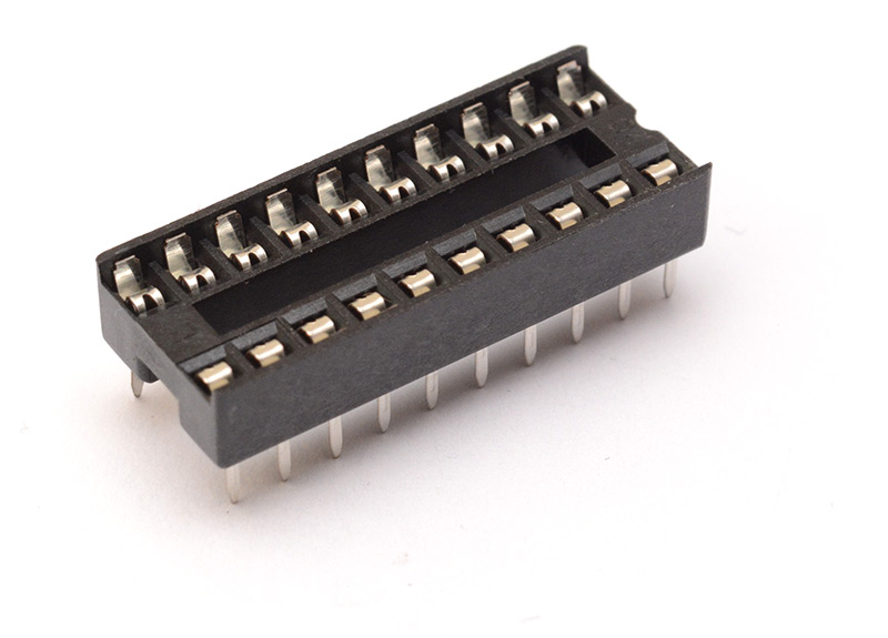
One 20-pin dual-in-line socket:
Two MAX7219 display drivers:
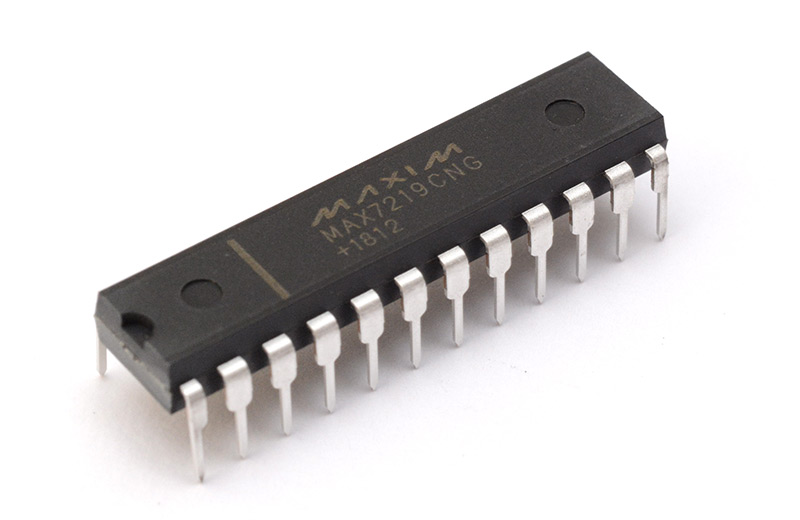
Note: Clock kits that shipped on 2021-01-13 may have faulty display driver chips. Please read this page and check the date code on the MAX7219 chips before assembling.
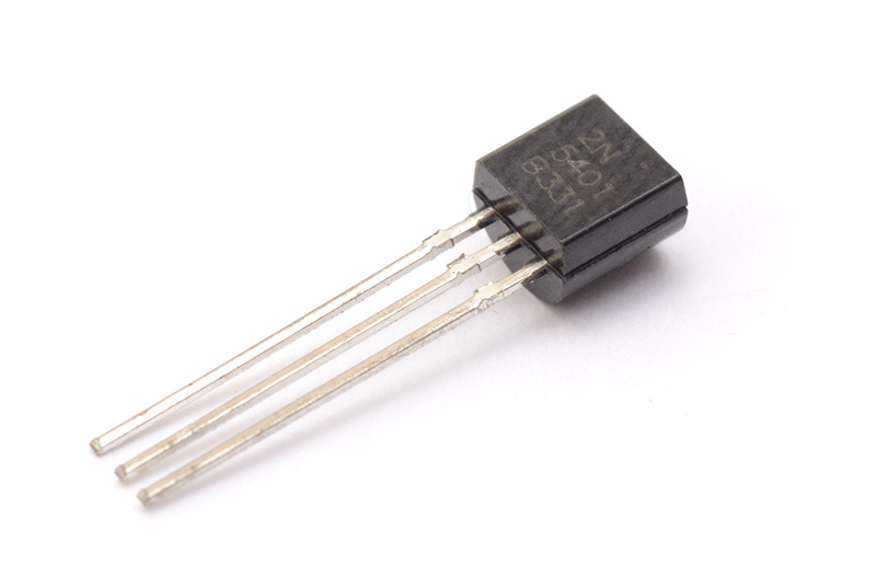
Two 2N5401 PNP Transistors:
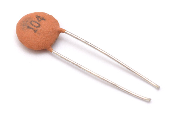
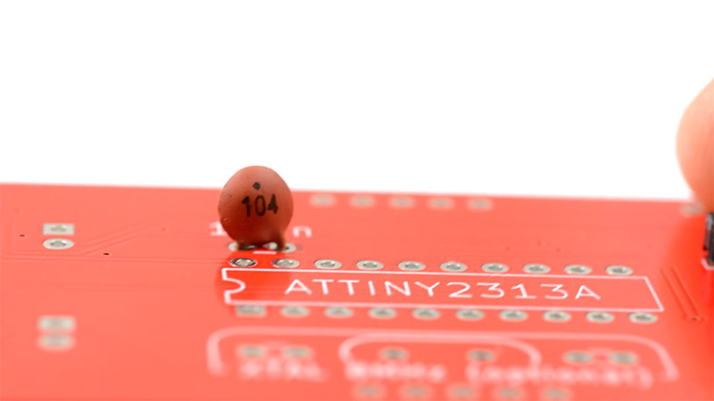
One 1uF Ceramic Capacitor:
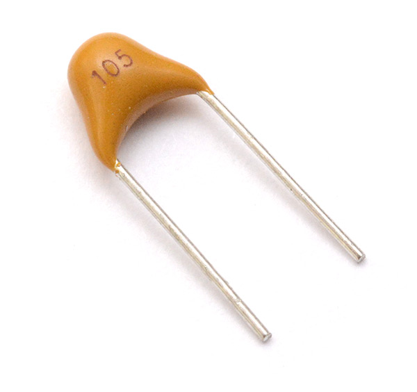
Note: A small number of clock kits sent out in December 2019 were erroneously shipped with an extra 0.1uF capacitor instead of a 1uF (labelled 104 instead of 105). Unless you plan to fit the optional regulator, the value of this capacitor is not important and the clock should still work fine.
Three 100nF Ceramic Capacitors:
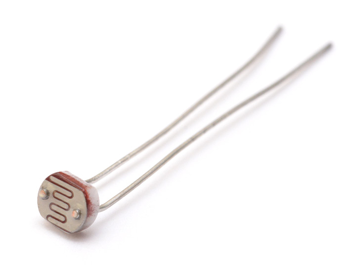
One LDR (light dependent resistor):
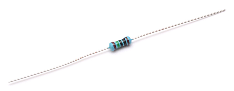
One 20k Resistor:
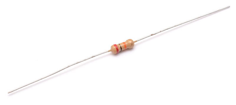
One 10M resistor:
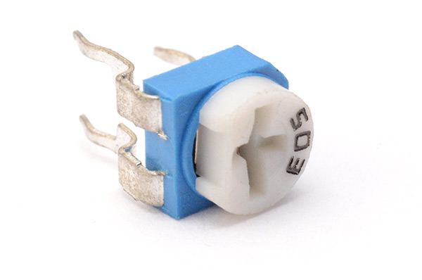
One 50k Potentiometer (trimpot):
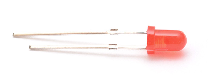
Nine 3mm red LEDs (note – they may have a clear plastic housing, but don't worry, they will still light up to be red):
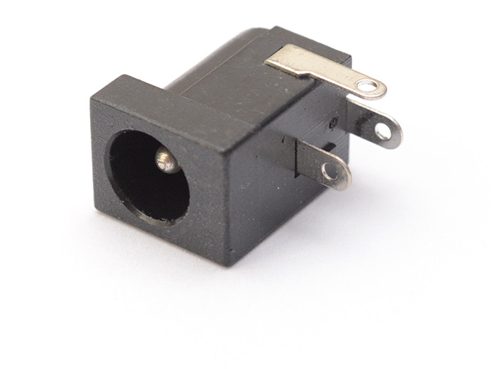
One 5.5mm x 2.1mm Barrel Jack:
One 5-pin header (this may be in the same bag as the GPS module):
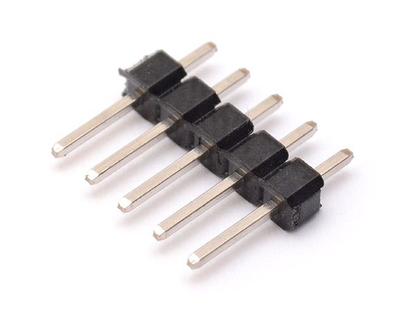
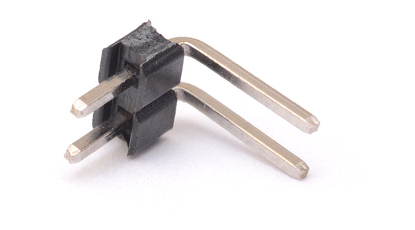
One 2-pin right-angled header:
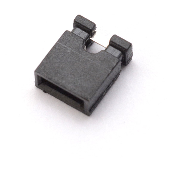
One pin jumper:
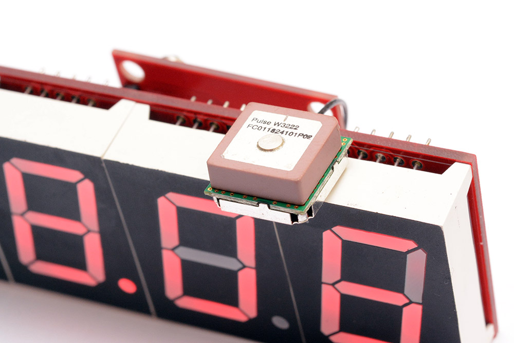
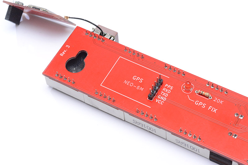
One GPS module, with antenna:
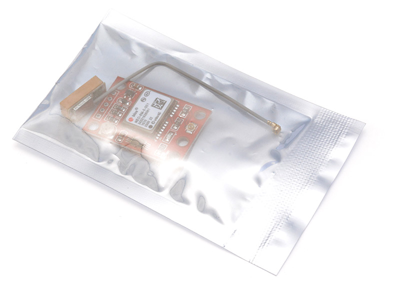
Some kits are now shipped with a slightly different GPS module (pictures here).
Note: I test every GPS module before shipping. You may notice that the bag has been opened and the antenna already fitted – this is only because I have tested the module and confirmed it's fully working.
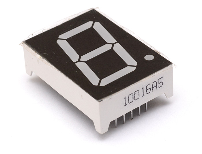
Eighteen one-inch common cathode 7-segment displays:
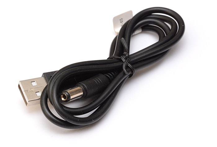
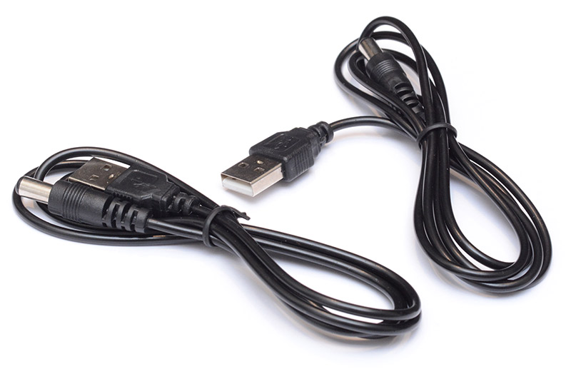
One USB power cable:
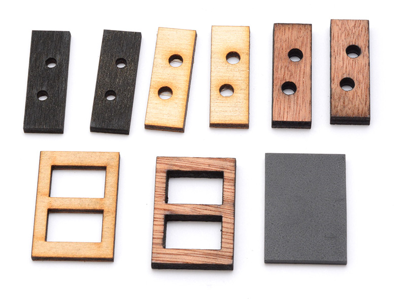
Nine laser-cut parts, of varying thicknesses:
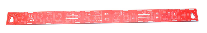
And of course the most important part, one big red PCB:
Steps
The order of soldering everything together isn't too important, the only thing to remember is that the digits, and the colon LEDs that sit in a laser cut frame, should all be left until the very end. Other than that, it's best to start with the smallest components, because they're the fiddliest.
1.
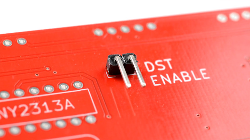
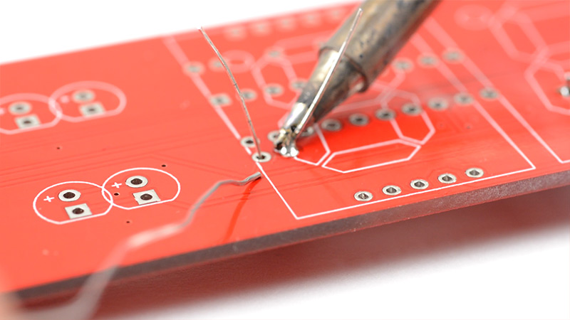
Start with the right-angle header for DST enable. If you live in a region that does not have daylight saving time at all, you can skip this step if you like.
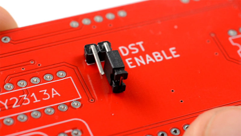
I used the jumper to help hold the part in place as I put the PCB upside down. This makes sure there is enough room to slide the jumper on and off the header later.
2.
Next fit the three 100nF capacitors. Ceramic capacitors do not have a polarity, so it doesn't matter which way round you fit them.
You can bend the legs outwards a bit, which will help to hold it in place as you solder. As with all of the through-mounted parts in this kit, you should cut the legs shorter after soldering the parts in place. You're allowed to leave all of them long until the very end, and cut them all at once, but I find it easier to cut them as I go.
3.
Fit the 1uF capacitor. Again it's a ceramic capacitor so there's no polarity to worry about.
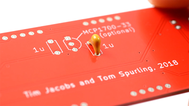
If we were going to fit the optional MCP1700 regulator, we would need to populate both of the 1uF footprints, but without the regulator only one capacitor is needed. You can fit it into either footprint, it doesn't make any difference.
4.
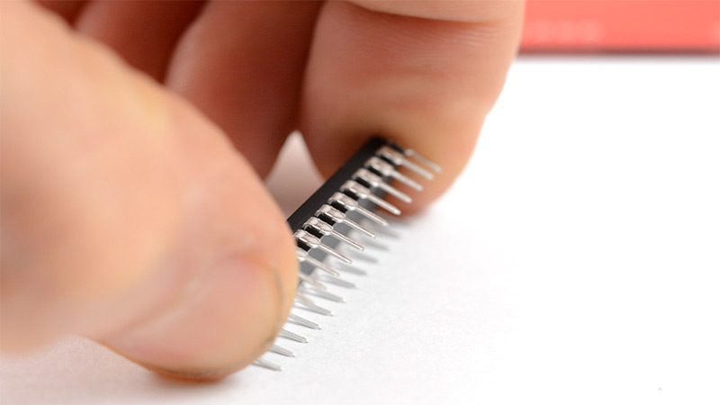
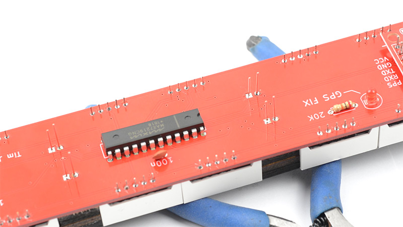
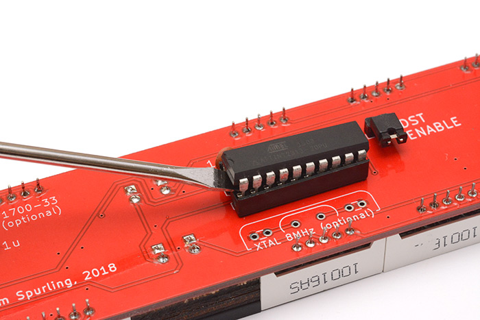
Fit the DIL (or DIP) socket to hold the ATtiny. The reason we are using a socket is so that it's easy to take the ATtiny out later, if we want to update the firmware. It also could potentially function as an expansion slot for a daughterboard to connect to!
There is a small D-shaped cutout at one end of the socket, which you should line up with the mark on the silkscreen printed on the PCB.
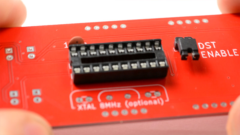
I tend to solder the corner pins first, so that everything is held in place for the rest of the joints.
5.
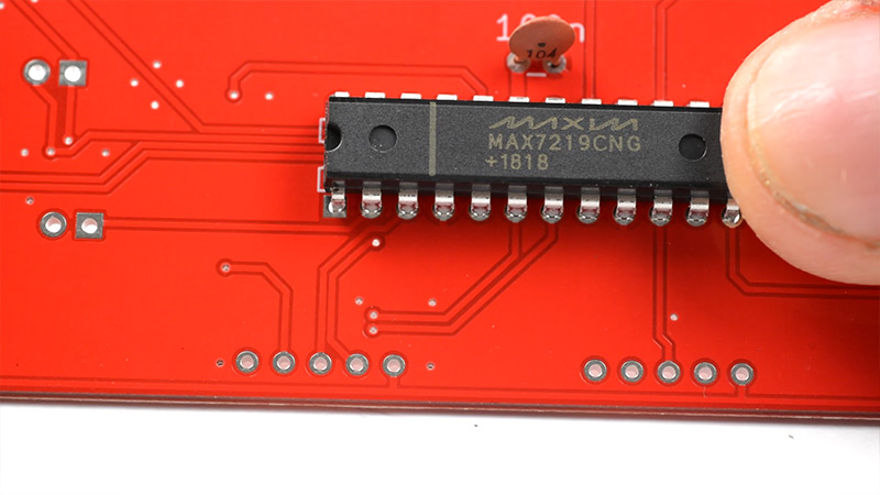
For the MAX7219 chips, you will need to bend the legs inwards slightly. The best way to do this is to press them gently against the desk. There's a knack to doing this neatly. Even if it's not too neat, as long as you can eventually fit the part into the holes in the PCB, you should be fine.
Make sure to line up the D-shaped cutout with the outline on the board. Double-check this before you solder it in place. If you fit the chip the wrong way around, the clock won't work!
6.
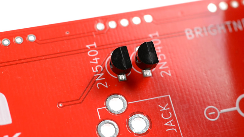
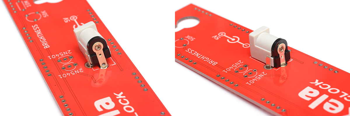
Fit the PNP transistors. The flat side needs to match the flat side of the outline on the PCB. Sometimes the transistors are made with straight legs, so you have to bend them outwards a bit to fit into the footprint.
7.
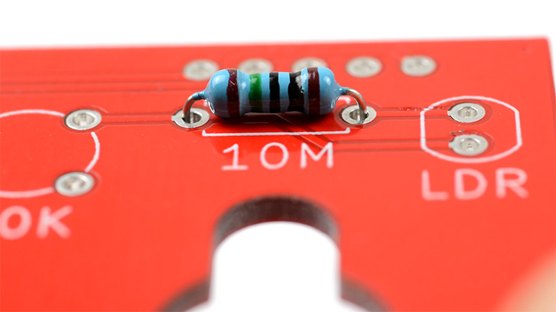
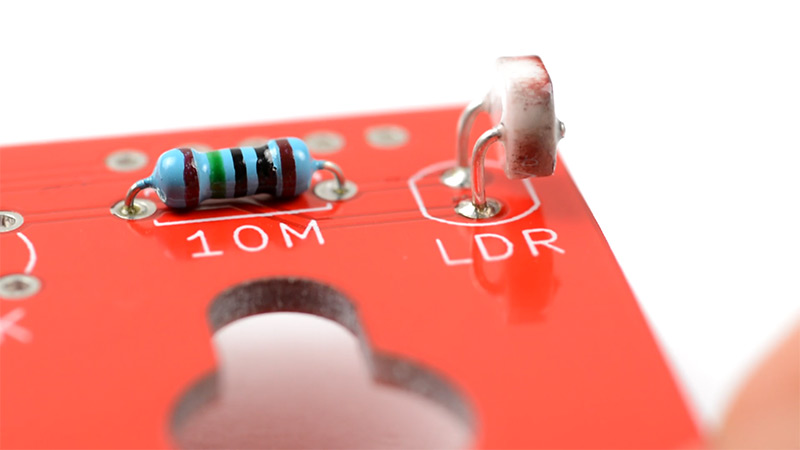
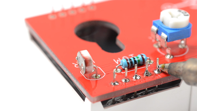
Fit the 10M resistor. This sets the minimum brightness of the clock. If you don't fit this part, at night time the display will go so dark you won't be able to read it.
8.
Fit the LDR. This is the light sensor that controls the brightness of the display. I bend the legs so that the LDR faces sideways off the edge of the board, which I find works well when the clock is against a wall. If you have a place in mind for the clock, it might make sense to point it in a different direction, or leave the legs longer so you can decide later.
9.
Fit the 50K trimpot. This controls the maximum brightness of the display.
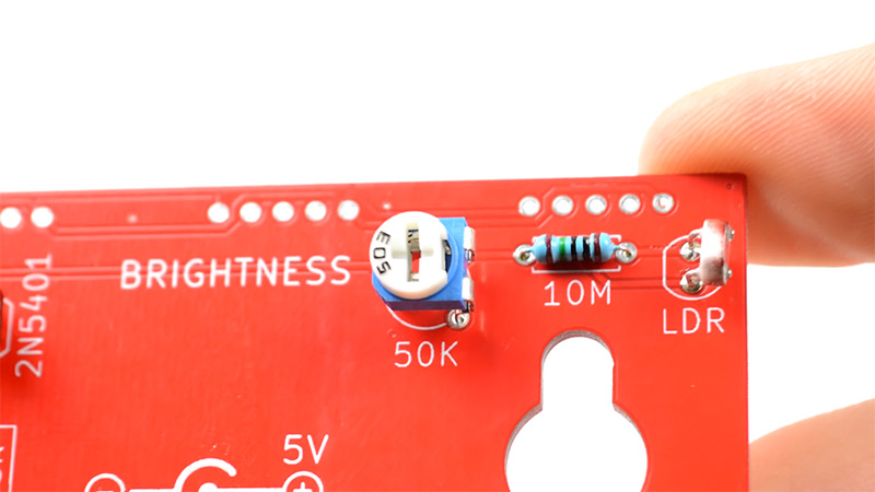
After you've fitted it, you can adjust this using a screwdriver (or your fingers if you're dexterous). I suggest leaving this in the middle though. I mostly wanted this to be adjustable so that you can turn the brightness down if it's annoying.
10.
Fit the barrel jack.
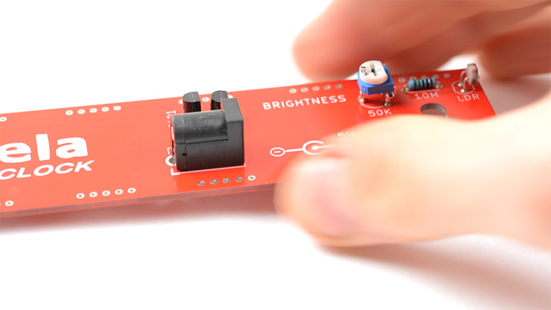
On the "Rev 3" PCB, these holes are huge, and the pins are very flat, so it will take a lot of solder to fill up the gap. The newer "Rev 3b" PCB has plated slots, which should make it a little easier.
Patience is important, you want the joint to be nice and clean because this is where all the power to the board comes in. It's also good if it can withstand the mechanical strain of someone violently yanking the cable out. It could happen!
Note: In January 2022, my supplier sent some slightly different barrel jacks, moulded in white plastic. I thought these were identical, but the footprint is slightly different. If your kit shipped with one of these white ones and the "Rev 3" PCB, you may need to use some pliers to crush the rear pin a little bit, so that it fits into the footprint more easily.
11.
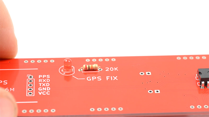
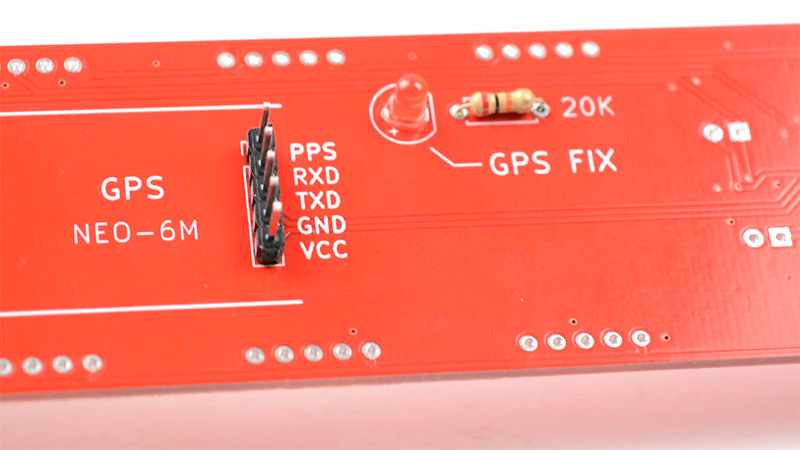
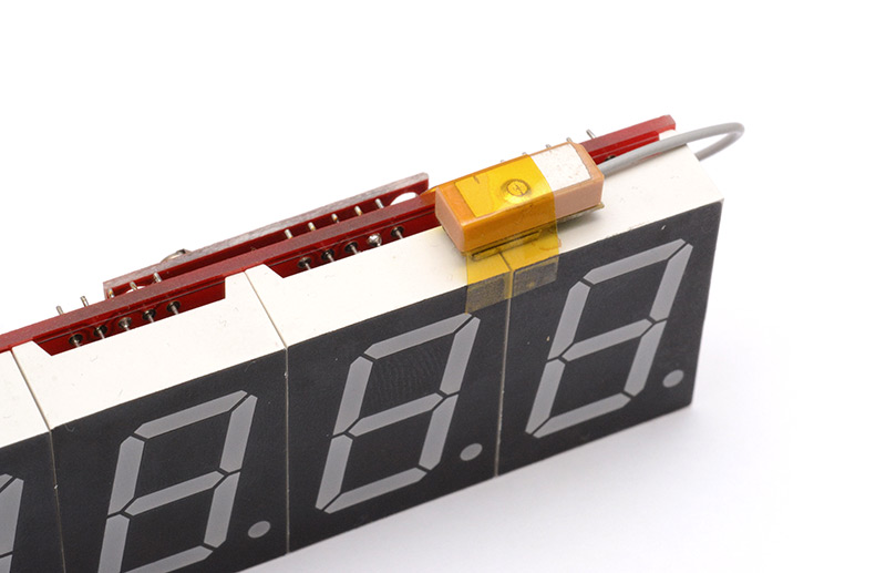
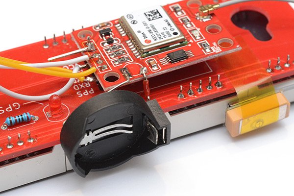
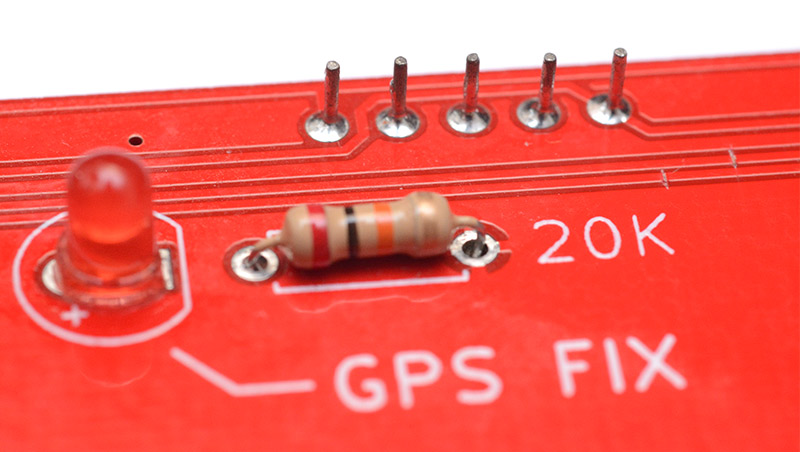
Fit the 20K resistor and the 3mm LED to the "GPS Fix" indicator. You can skip this step if you want, since the GPS fix is also indicated by the colons blinking. I like to have this little LED though, because the colons are controlled through software, but this LED is hard-wired to the PPS signal. It will light up at the start of a second with an accuracy of within 50 nanoseconds.
LEDs have a polarity: you need to fit them the right way around. The long leg is the anode (the positive side), and the short leg is the cathode (the negative side). There is also a flat spot on the LED moulding itself next to the cathode, so even if the legs are trimmed down you can still work out which side is which.
12.
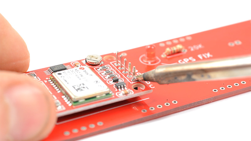
Fit the 5-pin header to the GPS footprint. If you are planning on experimenting more with the GPS unit, you may want to attach it using some wires instead of this header, as that'll be easier to desolder, if you want to do that later. Another option is to fit a female header connector to the GPS module, and then you'd be able to hot-swap them.
Before you solder the GPS unit in place, I recommend you fit the antenna to it. In the video I forgot to do that until the end. You need to align the tiny coax connector and press down firmly until it snaps into place.
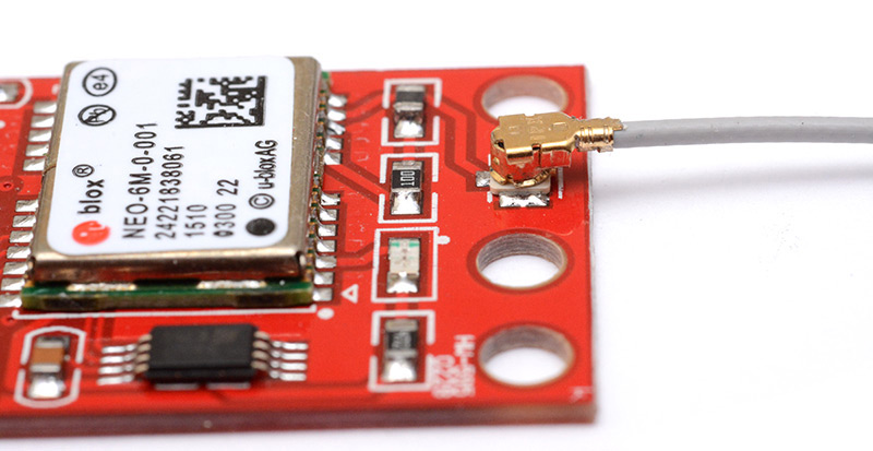
You can then solder the module in place. For it to look neat, I solder one leg first, then gently melt the join as I lift the module to be parallel to the board underneath. Then once that joint has cooled, you can let go and solder the rest.
As of May 2024, I have started shipping kits with a different GPS module. If you have one of the smaller modules, you may want to mount it backwards in order to keep access to the antenna.
13.
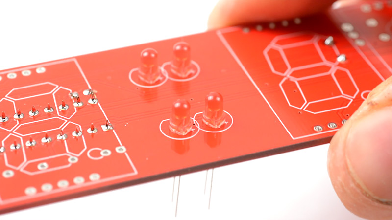
It's time for the other side of the board! First up are the four LEDs which illuminate the timezone indicator. Remember to get the polarity right: long leg is +.
These can be soldered flush to the board.
At this point, take a good look at the circuit board so far. If any soldering joints don't look right, now is the time to try and fix them, because once they're hidden under the display it becomes a lot harder to get to them.
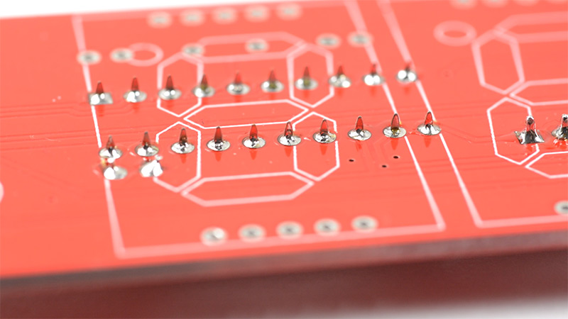
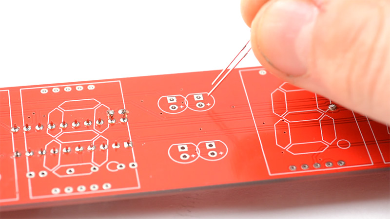
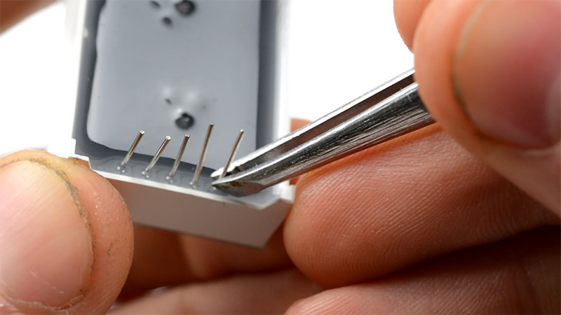
Before we fit the digits, it's important to look at each one and straighten the legs. They always arrive with most of the legs squashed, and you need to gently bend them back with tweezers or pliers, otherwise you'll have a hard time fitting them into the PCB.
You also need to peel off all of the protective films (trust me, it's a lot easier to do this before they're soldered down).
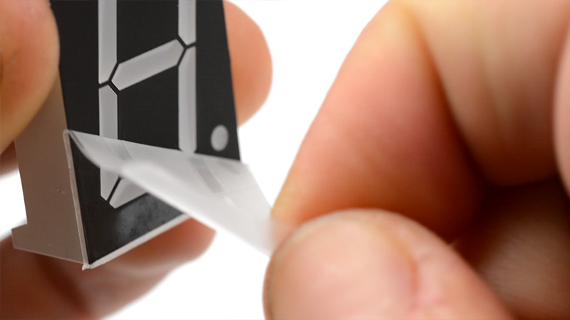
Fitting all of the digits is quite tedious, and if you're not careful it's easy to accidentally turn it upside down and most of them will fall out. Make sure that the decimal point is at the bottom, just like the outlines printed on the PCB.
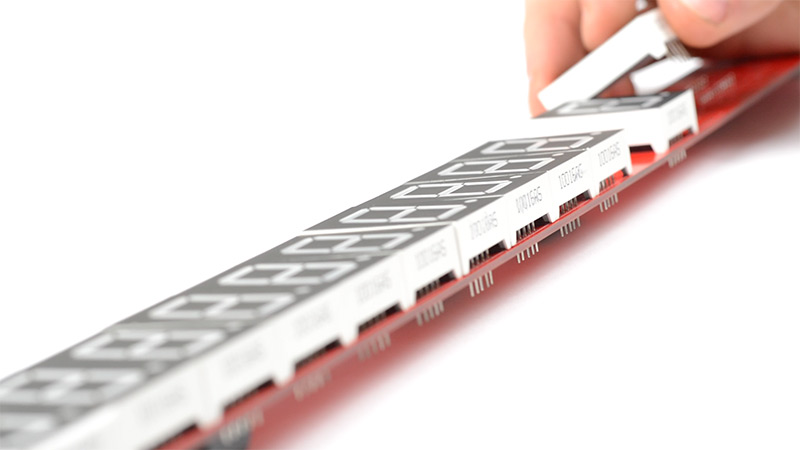
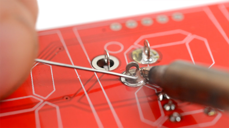
Finally there's the mammoth task of soldering all 180 pins. It doesn't take all that long really, and it's excellent practice for getting nice clean solder joints.
14.
For the colon LEDs, as an optional step, you may want to file down the top of them. You can do this with sandpaper or a needle file. It's not too important (I didn't do it in the video) but it will improve the viewing angle and make them flush to the board. If you want to do this, it's much easier to do it before soldering the LEDs in place.
Before we can solder the colon LEDs, we need to glue the laser-cut parts together. There are two sets of three plywood pieces. The black-painted piece needs to go at the top, and has holes that the LEDs can poke through snuggly. The other parts need to be glued behind it, with the wider holes lining up.
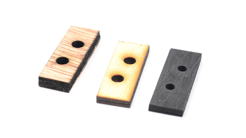
The video shows how to do this, but if you are not used to using super-glue, I advise you to use very little of it. Shake the container before you pour it out so that it's mixed properly (often, cheap glue is diluted, and if it separates you'll pour out a liquid that doesn't glue things together well at all).
When you stick the pieces together, keep pressing on the sides and the top, so that the boards are not mis-aligned. You want to be sure that it will fit between the digits on the PCB.
When the glue is set, you can slide the LEDs into the board (again, check the polarity) and push the laser-cut frame over it. Then, push the LEDs forwards so that they poke out a bit, and solder the legs in place.
You may find that you need to file or sand down the edges of the laser cut parts, the tolerance is quite close.
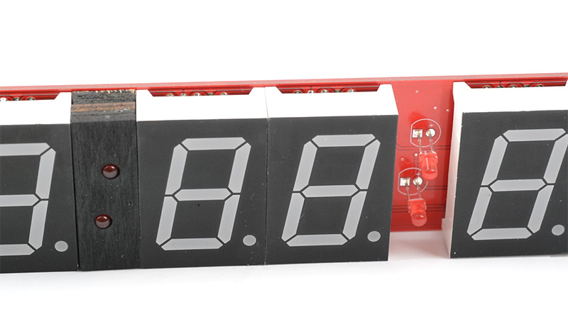
When you're soldering the LEDs, be careful that when you turn the board over you don't push them out of alignment. I used the handle of my wire cutters to support the board as I soldered this step, so the LEDs weren't pressing against the table.
15.
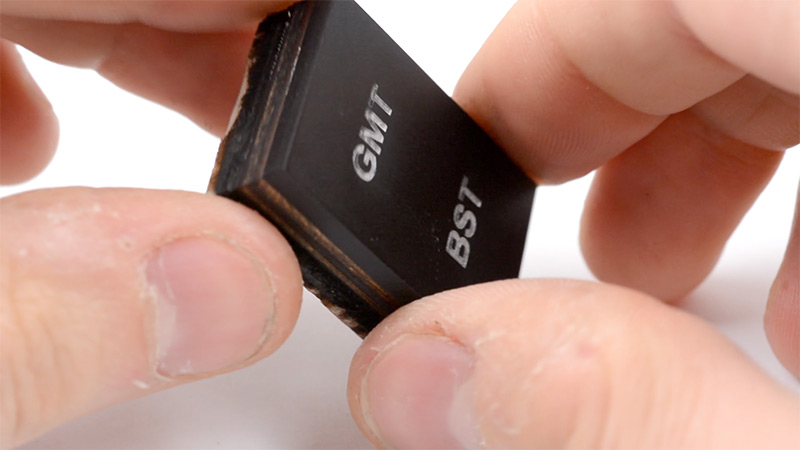
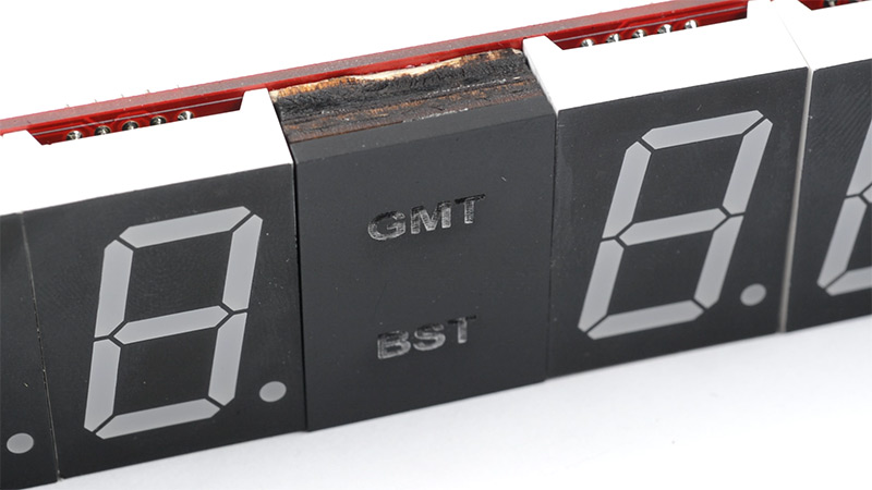
The timezone marker is comparatively easy to glue together. Just be sure that the pieces line up to be able to fit inside the gap between the digits.
Then use a small amount of glue to attach it in place.
The last thing to do is fit the ATtiny into its socket. Make sure to line up the D-shaped cutout with the marking on the board (and the cutout in the socket). If you're in doubt, the text on the chip that says "ATTINY" should be the same way up as the text on the PCB underneath it.
An optional extra last step: if you don't like the GPS antenna to be dangling off the end, you can tape it on top, like this. I don't think it has any effect on the signal strength as far as I can tell.
16.
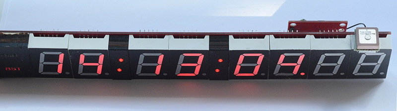
It's time to power up the circuit! Plug in the 5V power cable and connect it to a suitable supply (such as a USB power adapter). The display should light up with hyphens all the way across, and the seconds/centiseconds should start ticking.
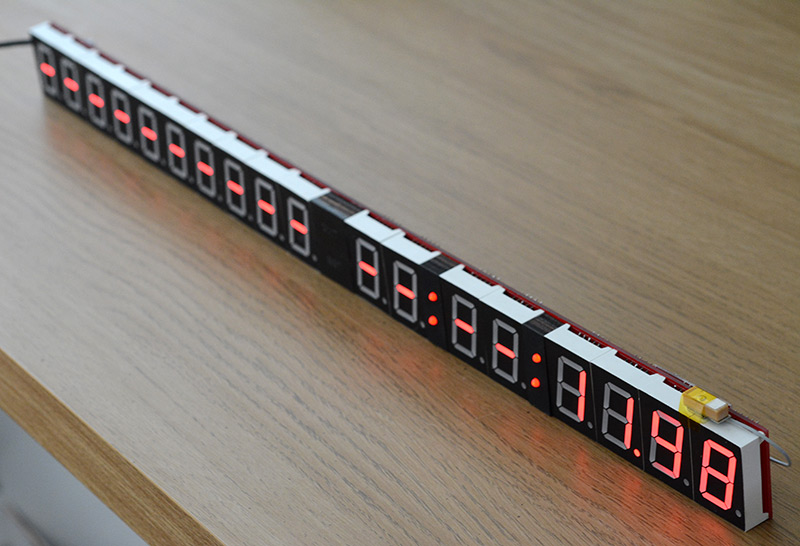
You now need to leave the clock to do its first-time warm-up, which will take anything between ten minutes and a few hours.
Usually the display will suddenly update to have the time and date within about 20 minutes. I recommend leaving the clock near a window, or even better to take it outdoors. Lots of electronics like TVs and computers can give off electromagnetic noise which can interfere with the GPS signals.
Eventually, it will have found enough of the satellites to have a GPS fix, and this will be shown by the colons flashing on and off each second. Also, the "GPS fix" LED on the back will be blinking once a second. The time will now be exactly right.
Troubleshooting
Update (Jan 2022): I've added an interactive board viewer here. If you select the netlist tab, you can highlight individual signals which can help with continuity checking.
Here are some examples of problems people have encountered.
- (October 2020) GPS Fix but no time display: If the GPS gets a fix (LED blinking once per second) but the clock display has not updated to show the correct time and date, this could be due to a different type of GPS module that was shipped with a small number of kits, between September and October 2020. The ATtiny firmware has since been updated to support both GPS types. If you think your kit is affected, send me an email and I'll ship a fresh ATtiny chip with the updated firmware.
- All segments lit, or half of the clock is displaying 8888-88-88: This was caused by a soldering error on the driver chip for that half of the clock, re-soldering the legs from the back of the clock was enough to fix the problem.
- Ticking very fast then jumping back to the correct time each second: Affected a clock where the GPS module was positioned a few metres away from the main clock. The cable connecting them apparently caused some interference between the serial data and the PPS signal. The clock expects the PPS to light up once a second, so sending serial data into it will make the clock try to tick faster and faster to keep up. The fix was to replace the cable, if using CAT5 then I'd recommend using one of the twisted pairs for PPS and GND. It should function fine with a cable of at least 15 metres, probably more.
- No sync, ever: It can take several hours for a cold start to complete its scan of the sky, so I still recommend leaving the clock outside for a few hours to check if it's working at all, but if you've not had any luck it could be a problem with the antenna. Some people have had problems with the fiddly little connection between the antenna and the module. In a few cases simply re-seating the connector was enough to get it to work. At least one person had a broken antenna, that may have happened during assembly or maybe even just during shipping. If you think you're having antenna problems, I strongly recommend upgrading to an active antenna as described further down this page.
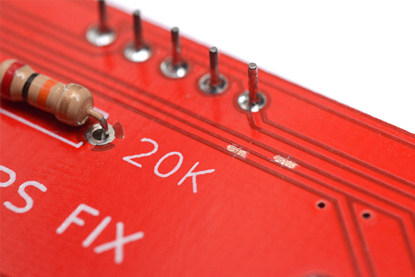
Note: Another reason the clock might not be able to sync is that there's a soldering error where the GPS module connects. I've had a few cases where people replaced the GPS module only to find that it was a soldering mistake all along. There are two LEDs on the back of the clock, one big one labelled "GPS Fix" and one small square one on the module itself. When you power on the clock, the LED on the module should be lit solidly, and the GPS-fix LED should be off. If that isn't the case, or if the GPS-Fix LED is ever lit continuously, then there's a soldering error somewhere.
- One segment is dimmer than the others: A poorly lit segment is unfortunately a sign that the display suffered some damage during soldering. This is quite a rare thing to happen but is most likely due to the part being overheated. I recommend using a temperature-controlled iron, but it is possible to assemble the clock with an unregulated iron if your technique is correct. Anyway, if this happens the only solution is to replace the digit. The easiest way to do that is to cut the legs of the part to make removing it easier, then use a desoldering tool (such as a solder-sucker) to remove the legs individually.
- Date display occasionally shows junk: This was a mismatch in the baud rate of the ATtiny and the GPS module. The ATtiny chips are now calibrated before I send them out, but for a while I was shipping chips which had just been briefly tested. The oscillator is temperature-sensitive, and one person found that on cold days their clock stopped working correctly. The tolerance on the oscillator was such that this change in temperature was causing UART errors. The fix is to fit a new chip that's been calibrated correctly. Or, for more extreme temperature swings, fitting the crystal oscillator and configuring the chip to use that as a reference should help.
- Colons blinking but time displayed is exactly two seconds fast: This only ever happens shortly after powerup and is a result of the GPS module choosing the wrong leap-second offset. This offset (the difference between GPS time and UTC) is only broadcast once every 12.5 minutes, so under certain conditions it's possible to acquire a GPS fix before the leap-second offset is known. In that case, the module makes a guess at the offset and is usually off by a few seconds. The problem will fix itself within at most 12.5 minutes, usually faster. I only recently found out about this problem, and in a future firmware update I'll ensure that the colons don't blink unless the leap-second offset is known.
How to change the timezone
You will need a way of loading new code onto the ATtiny microcontroller. The way I do this is with a USBASP adapter, which costs about £1.50. I believe you can also use an Arduino as a programmer instead, so if you already have one of those that might be easier. (Update: one clock owner has shared instructions on using an Arduino here.)
I have a special test clip which I've wired up to reprogram these chips without taking them off the board, but if you're not doing this all the time it's probably easier to stick the chip into a breadboard.
Power off the clock, and remove the ATtiny from its socket. Don't be tempted to use your fingers, it always ends with the legs getting bent. Use a screwdriver to lever it up from one side, then the other side, and keep working it until it comes out.
Use some male-to-female jumpers to connect the USBASP to the breadboard.
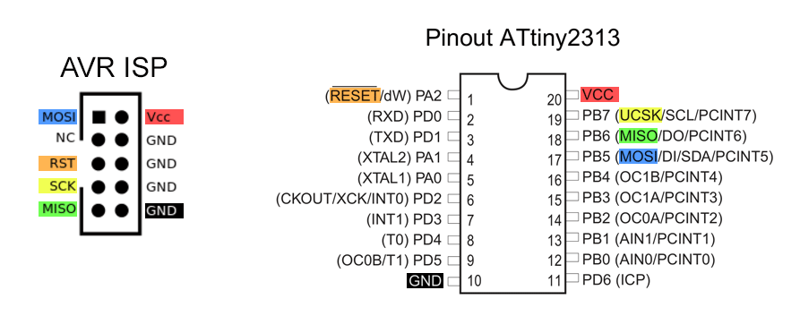
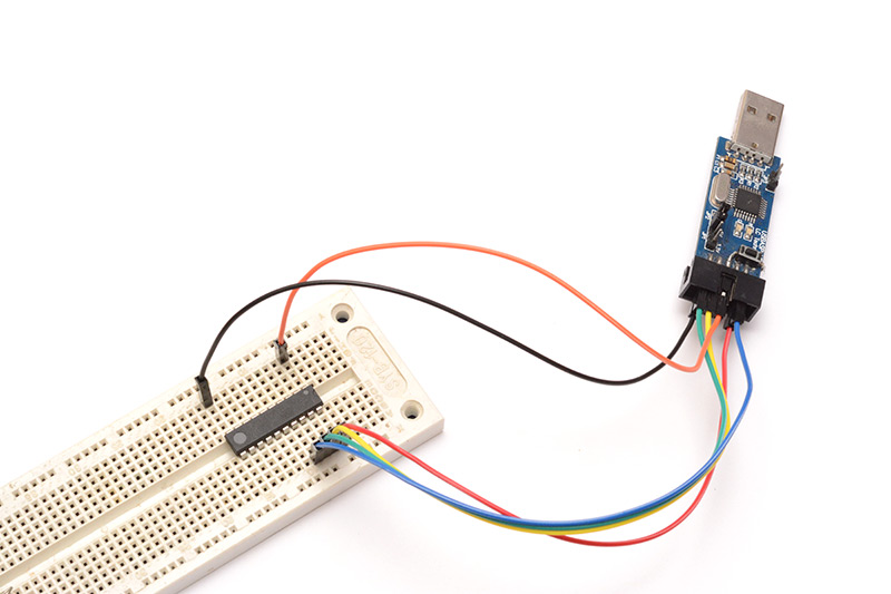
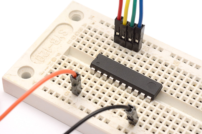
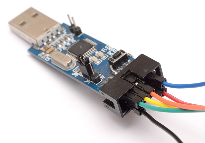
There's a little jumper on the USBASP board that sets the voltage. Either 5v or 3.3v is fine, just make sure the chip is powered.
In the source code repository I've included a build folder which has pre-built hex files for different time zones. If the one you want isn't there, let me know!
You need to install the "avrdude" software to load this file onto the chip. On some platforms, you may also need a driver (such as libusb) to use the USBASP. I can give more detailed instructions if anyone needs them, or you can try googling for it – there's a lot of information about doing this out there.
The command to flash the chip to US Eastern Time would be:
avrdude -c USBASP -p t2313 -U flash:w:us_eastern.hex:i
Or if your ATtiny chip is actually an ATtiny4313:
avrdude -c USBASP -p t4313 -U flash:w:us_eastern.hex:i
Then stick the chip back into the clock, and see if it works! For timezones which don't have daylight saving, you will want to have the "DST enable" jumper not fitted, or it'll be permanently an hour ahead.
Optional Steps
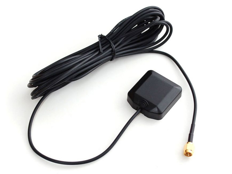
Fit Active Antenna
This is a thoroughly worthwhile upgrade if you're having signal strength problems. An active antenna can be had for about $10 and will significantly improve the reception.
The antenna connector is a u.fl type, and the module provides a bias voltage of just under 3.3V. There are adapters from u.fl to SMA if you want to expand the options available to you.
The part number for the antenna above is GPSMOD1315 from Pulse Larsen, I can confirm that it works with the GPS module on this clock. It has a gain of 15dB, it's possible to get antennas with higher gain but too much gain can apparently cause problems for these modules.
Many thanks to John (QxStuart) for his investigations into different antennas.
Update: Another type of active antenna is the "magnetic puck" type. These usually have a 3m or 5m cable and an SMA connector. The part number for the one I have here is Trimble 66800-52.
To use this with the clock, you need an SMA to U.FL adapter.
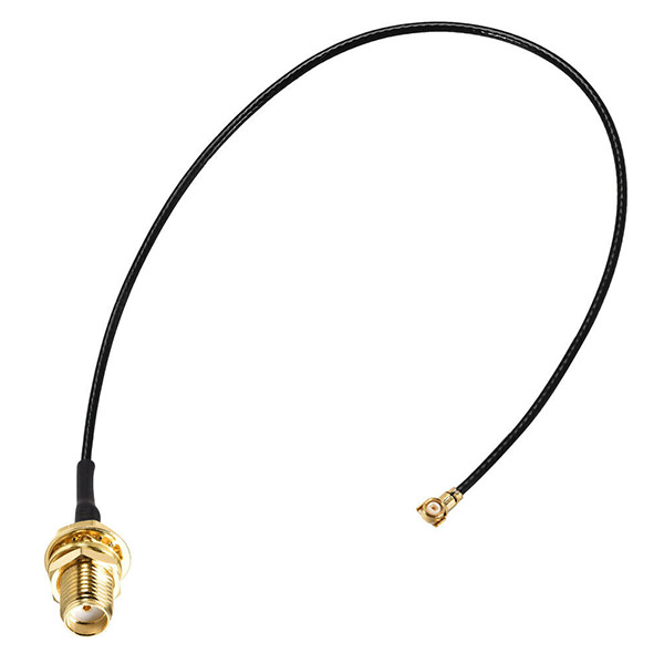
This antenna works very well, I regret not advising people to try it sooner. I dismissed it since the older type of GPS module I used when developing the clock did not provide the bias voltage for active antennas to work, but the newer type does provide the 3V bias needed. Note that some active antennas expect a 5V bias, which the module doesn't provide.
In addition to being a good antenna, it's also waterproof so it can be mounted outside. All in all, it's an excellent way of improving GPS reception.
Fit LDO
All of the GPS modules I could find now have their own 3.3V regulator on board, so they can run straight from the 5V supply. The module I used in the original clock would only run from 3.3V though, so I originally planned to have a regulator on board.If you want to use a different GPS module that only supports 3.3V, you can fit the regulator here. You need to cut the trace between the "in" and "out" legs on the board for it to work.
You also need to add another 1uF capacitor in the remaining footprint.
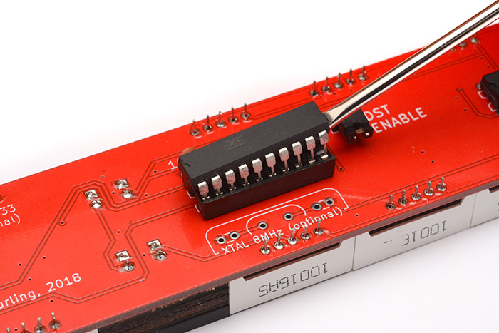
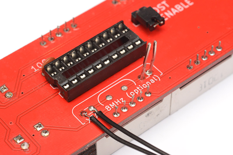
Fit Crystal
You can solder an 8MHz crystal into the footprint next to the ATtiny to give it a more stable oscillator. The footprints on either side are for load capacitors, which will need to be matched to the crystal, with values of a few picofarads. By carefully selecting the load capacitance, you can adjust the crystal's frequency slightly, and dial it in to a perfect value. (But it will still vary with temperature, of course.)There is not much point in doing this normally, because the interpolation tracks the PPS signal from the GPS very accurately. If the GPS loses its signal, and the PPS signal stops, the GPS unit continues to spit out what it thinks the time is, which will eventually drift away from what the ATtiny is displaying.
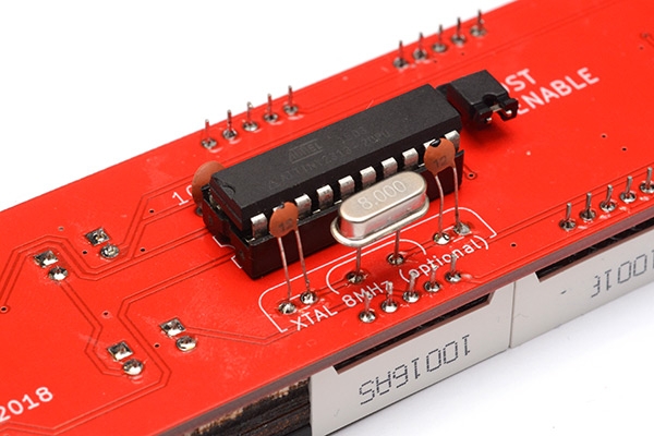
In the picture, I left the leads long, so I can edit the capacitance if needed.
If you fit the crystal you will, at the very least, need to change the fuse settings on the ATtiny to tell it to use the crystal as a clock source. (Set the low fuse to 0xCF) You will also probably want to use a slightly modified firmware image, that ignores the GPS data if it is not giving a PPS signal.
A better option would be to fit a temperature-compensated clock source, but I am still researching the best solution here. I may release an expansion board that augments the "offline" behaviour of the clock.
Extra Capacitors
I'm not convinced this makes much of a difference, but you may want to add some big electrolytic capacitors to the power rails near the MAX7219 chips. When running at full brightness they're switching a fairly substantial current, which is potentially causing electromagnetic interference (EMI). An alternative version of the display driver chips from Maxim is specifically slew-rate limited to reduce EMI, so they clearly thought this was a problem.Adding a 10uF in parallel with the 100nF capacitors already there may help to reduce the noise on the power line.
If you find it too tricky to solder multiple capacitors to the power rails around the MAX7219 chips, another option would be to stick a big capacitor (say, 47uF or 100uF) in the remaining 1uF footprint. Note the polarity if you do that – the pin connected to the ground plane (copper pour) is of course the ground pin.
The reason not to add too much capacitance is that it goes against the USB specification. Lots of capacitance causes a large inrush current when it's first plugged in, which can cause a USB hub to think there's a short and cut the power entirely. If you're only powering the clock from a mains-to-USB adapter then this probably isn't a concern.
Battery Backup
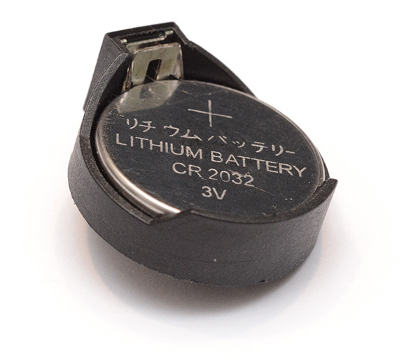
The provided GPS module has a small supercapacitor which is supposed to allow the module to keep time and maintain its volatile memory while powered off. But in my experience these things are extremely unreliable, and go flat in anything between a few minutes and a few hours. (To contrast, the original MkII clock that I built had a module which is no longer available, but that one seems to remember the time even after a few weeks of being powered off.) The real benefit of keeping the module powered is that it can do a warm start. With the clock on my windowsill, I can power it on and it will usually have a full GPS fix within about ten seconds.If you want to power off the clock for more than a few minutes at a time, the best thing to do is to replace the crappy supercap with a 3V coin cell battery.
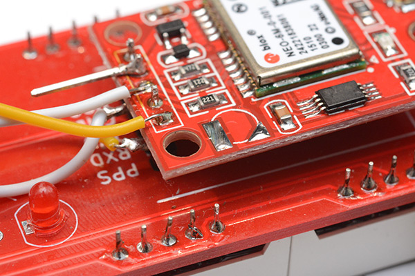
The supercap is located on the corner of the GPS module. Ignore the extra wires in these pictures, I'm doing this to my debugging clock which has been victim to several experiments.
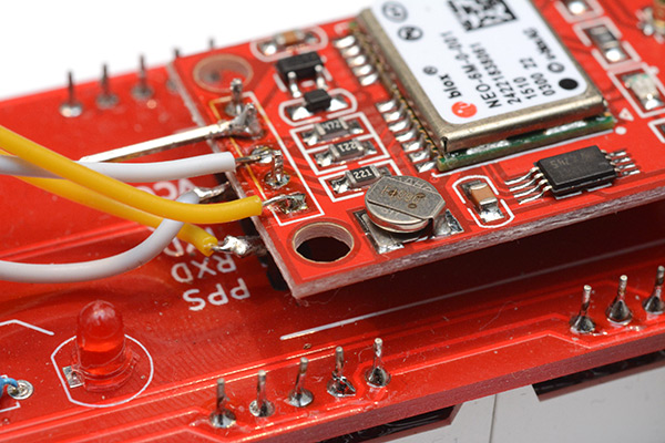
To remove the supercap you can either use a heatgun or a soldering iron. It's quite fiddly with a soldering iron but you're less likely to desolder everything else in the process. Just melt one edge, lift it up slightly, and melt the other. You could also simply use a razor blade to remove the supercap, but be careful not to cut the traces on the board.
The rectangular pad is the ground pin, the triangular pad is the positive pin. I decided to stick the coin cell holder on top, which isn't particularly elegant. The stiff wires hold it in place. With some planning, you could glue the battery holder somewhere else on the back, and use longer wires.
With this, it's possible to take the clock outside until it gets a GPS fix, then power it off and take it indoors, where it will find the fix much sooner than it would have done otherwise.
NTP time source instead of GPS
If you really can't get a GPS fix indoors, you may want to consider ditching GPS entirely. If you desolder the module and connect a USB-serial adapter in its place, you can send fake NMEA strings to the clock from either a desktop computer or a raspberry pi. Network time is generally accurate to within 50 milliseconds which should be plenty good enough for most uses.Only three wires need connecting: Ground, PPS and TX. The TX on the USB-serial adapter should connect straight to the TX pin on the PCB (the labels are there to match the footprint of the GPS unit, there is no need to worry about cross-over). The PPS signal should be connected to RTS on the USB-serial adapter.
In the source code repo there is a simple python script which will synchronize the clock very accurately to align with the system clock of the device running the script. Of course, make sure that the network time service is actually enabled and running on your device if you want it to be accurate.
Even better time sources
The reason for upgrading to a "better" (more expensive) GPS unit is not for accuracy, but for reliability. If you have the budget for it, there's an entire spectrum of GPS units intended for accurate timekeeping. Most of these devices are aimed at the high-speed stocks trading industry, where reliability is paramount. Using a marine style antenna will give a generally better GPS signal. Some of the more advanced units are specifically built to be immune to GPS jamming.Another extremely accurate time source is PTP, the Precision Time Protocol. This replaces NTP, again aimed at high-speed trading, and uses dedicated network hardware to compensate for routing delays to give a time pulse with picosecond accuracy.
If you happen to own a device like this, it's very easy to use it with the Precision Clock. Pretty much every accurate timekeeper is able to output NMEA strings at 9600 baud. By connecting this serial data and the PPS signal between the devices, the Precision Clock will simply function as a big precision display for the rack-mounted timekeeper. If anyone does this, please let me know, I'd be interested to hear about it.
Permanent Summer Time Scenario
The clock automatically switches between summer and winter time based on the rules programmed into it – in the case of the USA, that's the second Sunday of March and the first Sunday of November. If the "DST Enable" jumper is removed, the clock reverts to permanent winter time.The idea of the jumper was to allow you to disable the daylight saving if ever it got abolished. Unfortunately, in the case of California (PST = UTC-8), in the event that DST is abolished it's likely that the state will stay on Summer Time (UTC-7) all year round.
To cater for this scenario, after much thought, I've altered the firmware slightly, to essentially add another jumper to enable "permanent Summer Time mode". I chose to re-use one of the pins intended for the quartz crystal, for the following reasons:
- The pins are already broken out and unused on most clocks, so it's easy to ground the pin.
- Anyone who wants to use the quartz crystal will already need to re-program the ATtiny chip, in which case changing the timezone is easy.
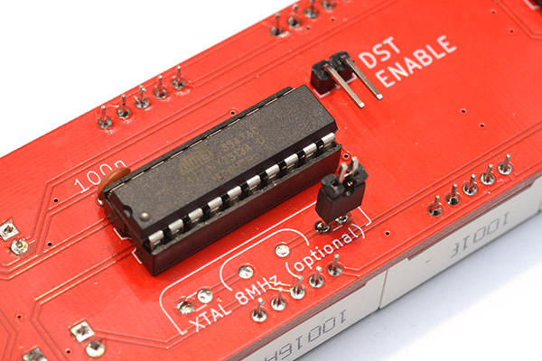
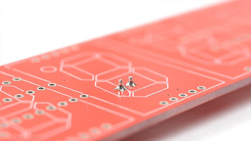
To enable permanent-summer-time, you need to connect pin A0 to ground, which can be achieved by placing a jumper on the rightmost pins of the optional crystal footprint. You could also simply solder a wire between them, which will probably be easier if the clock is already assembled.
Note: this firmware change was made on 2019-12-09, if you bought a clock that shipped before this date the above technique won't work. In that case you will need to reprogram the chip (using the method described further up this page) or, send me an email and I'll post you a new ATtiny with the up-to-date firmware on it.
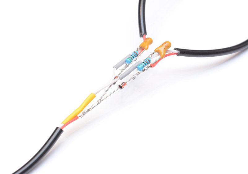
Dual Power Source
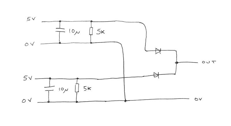
A splitter cable that lets you switch power sources without power cycling the clock is an idea I had recently. This is specifically for moving the clock from mains power to battery power, or vice versa, without losing the GPS fix.To build it I'm going to be cutting up two brand new, perfectly good USB cables.
We need one barrel jack and two male USB-A plugs, so you could cut up any old USB cable for the second USB-A.
The idea is to use two diodes to select the power source. It becomes slightly more complex when we remember the way the USB power banks behave: there's a boost converter inside, that's actively producing the 5V, which is turned on when it detects a load. When the clock is powered from another source, there won't be any load on the battery you've just connected, until the first source is removed. It might power up fast enough to not disrupt the clock, but it's a gamble.
The best idea is to place a small resistor and capacitor in-line with each USB cable, that always presents a small load. That way the USB power bank will turn on, and stay on, well before the other cable is unplugged. I chose a 5KΩ resistor, which will constantly pull about 1mA. It will also drain the 10μF capacitor when not in use, which will cause an extra load when it's first plugged in. I chose those numbers after doing a few tests with the USB batteries I have to hand, you may want to experiment with your own ones.
I'm adding an extra challenge of fitting the circuit entirely into the split in the cable. This is very fiddly and means you have to plan where the heatshrink will go in advance. Adding a small bit of veroboard would work just as well and be much easier to construct.
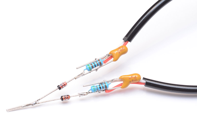
The best diodes to use would be Schottky diodes, with the smallest voltage drop. But the clock isn't picky about voltages, so I'm using regular 1N4148 signal diodes which are one of the most common in existence. The current is small, pretty much any diodes would do.
These USB power cables use red for 5V and white for ground. A standard USB cable will use black for ground, and white as one of the data wires. If you're unsure, just check with a multimeter.
With forward planning, the heatshrink that was slid onto the cables before we started can now take its place. I think it's about as tidy as we could have hoped for.
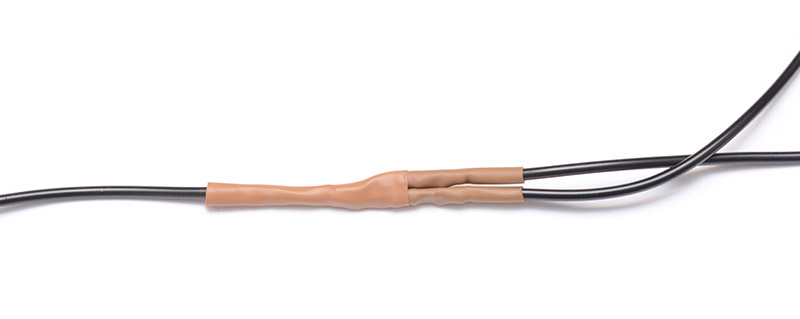
On the left is the barrel jack, on the right are the two USB ports. With this, I can confidently switch over from mains power to battery power and back again without worrying about waiting for it to find a fix again.
Disabling digits for reduced precision
A surprising number of people have expressed a distaste for the fractional seconds display, with at least five people asking me if there's an easy way to disable the last two digits.By far the simplest way to do this is to cut the cathode traces for those digits. Luckily, the two traces are easy to find on the back of the clock, running along just above the GPS fix LED. The cathode is the middle pin of the group of five pins at the top and bottom of each digit.
You don't need to remove the GPS module to do this, it just makes the pictures clearer.
With a sharp knife, cut the two traces immediately above the GPS fix LED and the 20K resistor.
I've staggered the cuts as it will make reversing the process later much easier, but if you want it to be permanent then it doesn't matter.
That's all it takes. You'll still have the decimal point after the seconds, so if you want to disable that too, you'll need to cut the DP pin for that digit. The trace is not nearly as accessible, so it's easier to just reach in with some snippers and cut the pin itself. It's the bottom right pin, looking at the front of the clock. Closest to the decimal point itself.
To reverse this mod, scrape away the solder resist around the cut traces...
...and use a blob of solder to bridge the gap.
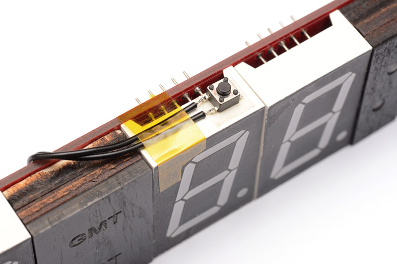
UTC to Local Time switch
A lot of people asked for this, and it should have been a feature from the beginning. A switch that lets you choose between local time and UTC.I updated the firmware to support this on 2020-11-05, so if your clock was shipped before then you will need to update the firmware, using the instructions further up this page.
Like with the permanent-summer-time mod, I'm re-using the footprint for one of the optional capacitors related to the unfitted crystal. If you have fitted the crystal, you will need to edit the code to make use of a different pin for the switch. I can help with that if needed. For most people though, the capacitor footprints are the most convenient pins to use.
Solder two wires to the leftmost pins.
A slide switch is probably best. Unfortunately I don't have any to hand, so I'm using this tiny tactile switch instead. This means I have to hold the button down to put it into UTC mode, and it jumps back to local time as soon as I let go.
I stuck it to the top of the clock with some double-sided tape and a snazzy strip of kapton.
In UTC mode, since neither timezone indicator is accurate, they are both turned off.