
MAX7219 Display Driver Problems (January 2021)
30 Jan 2021A recent batch of MAX7219 display driver chips turned out to be completely faulty. I have not yet determined exactly what is wrong with them – whether they are dead-on-arrival or if they're expecting some different voltage or frequency – but they definitely don't work with the clock kit.
Only clock kits shipped on the 13th of January 2021 are affected. The faulty chips can be identified by their date code being +2045.
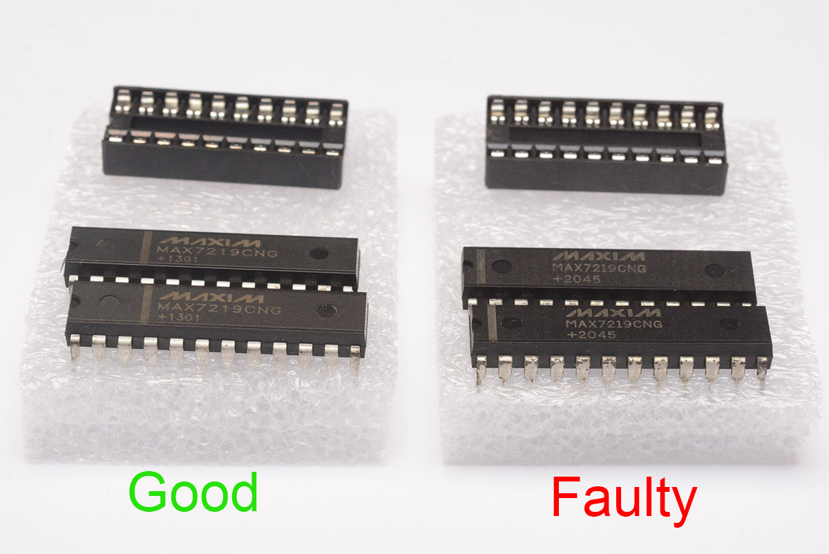
The logo and position of the stripe doesn't matter – only the date code +2045 indicates the faulty chips.
I sent out a bulk email to everyone I think is affected, if your kit shipped with these faulty chips just send me an email and I'll send you some working chips as soon as possible.
If you have already assembled the clock with the non-functioning chips...
Replacing the chips is possible without having to remove the 7-segment displays.The easiest way to do this is with a heat gun.
I set my heat gun to 360°C with a medium flow rate. Using a hotter temperature will work faster, but there's a risk of melting some of the surrounding parts. Luckily the MAX7219 chips are not too close to other parts on the board, apart from the little capacitors which should be fairly resilient.
It's possible to use an unregulated heat gun to do this, but I'd advise covering up the rest of the board if you do that. You can use aluminium foil to protect the rest of the parts.
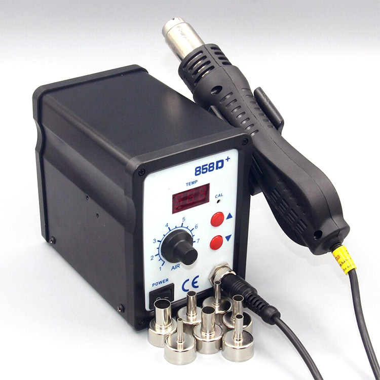
Here is the type of heat gun I use, it's a temperature-controlled generic one:
Here is a video of removing one of the max chips with a heat gun. In real time, it took almost a full minute of blowing hot air on the chip for the solder to fully melt. Again, if you use hotter temperatures it'll go faster, but it's less risky to use a lower temp and be patient.
It is technically possible to do the same thing in reverse to fit the new chip. Sit the new chip on top of the footprint, and heat it up until it sinks into place. However, you have to be absolutely certain that the legs are straight and parallel if you want to do it that way. If the legs are even slightly out of alignment, it becomes very frustrating, so I don't recommend attempting this unless you're confident about it.
It's much better to clear out the holes first. There are a few ways to do this, the easiest for me is to use a solder-sucker and the heat gun. Heat up the solder until it's molten, then suck the solder out. This is the type of solder sucker I use:
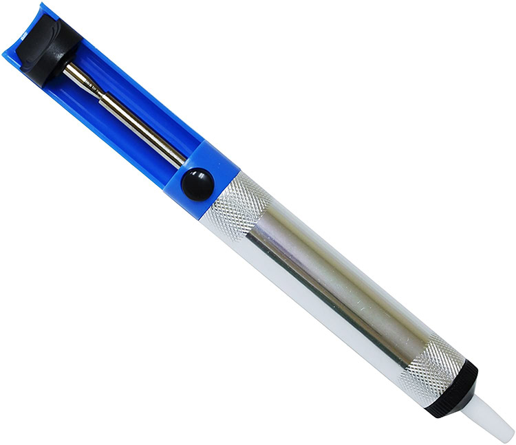
You press the spring-loaded plunger and then hit the button when you want it to suck. Here's a video of the process:
You may need to periodically stop and clear the old solder out of the solder-sucker.
Finally, fitting the new chip can be done by soldering from this side too. Heat up each leg with the soldering iron and add a small amount of solder. Gravity and capillary effect should pull the solder into the hole. Another video:
Be careful not to use too much solder here, it can dribble all the way through. Use too much and it may even short on the underside, which is then a real pain to fix.
If you do not have a heat gun
It's possible to remove the old chip by simply snipping the legs off and desoldering them individually. This takes a bit longer but is still a viable way of removing the chip.You can snip the legs with a small pair of diagonal cutters, or with a sharp knife. It's best to cut as close to the black plastic as possible, so you can grab the leg with some tweezers when it comes to removing it.
I hope that everyone is able to replace the chips without too much stress. Apologies once again to everyone who received kits with the affected chips. As always, if you have any troubles, just send me an email and I'll do my best to help.