
| Loading_M_ | Posted: 7 May 2026, 02:52 AM |
|---|---|
 Member Posts: 12 Joined: 7-May 26 |
It's been a bit since I've done any serious soldering work, and I might have made some mistakes when soldering up the Mk. IV board I just got. I'm not sure what the issue is though, and I'm looking for help troubleshooting. When I powered on initially, and now, some segements light up, although it's not been consistent in which segments light up. See the first picture for what happens right now.  I also tried disconnecting the date side, to hopefully isolate the issue, but that doesn't seem to change the behavior at all. I did briefly get a d2 error one of the times I powered it up (without the date side attached), but it powered off shortly afterward. I haven't seen that error since. I also briefly saw some loading animations, but again, it shut off within a second or so, and hasn't happened since. 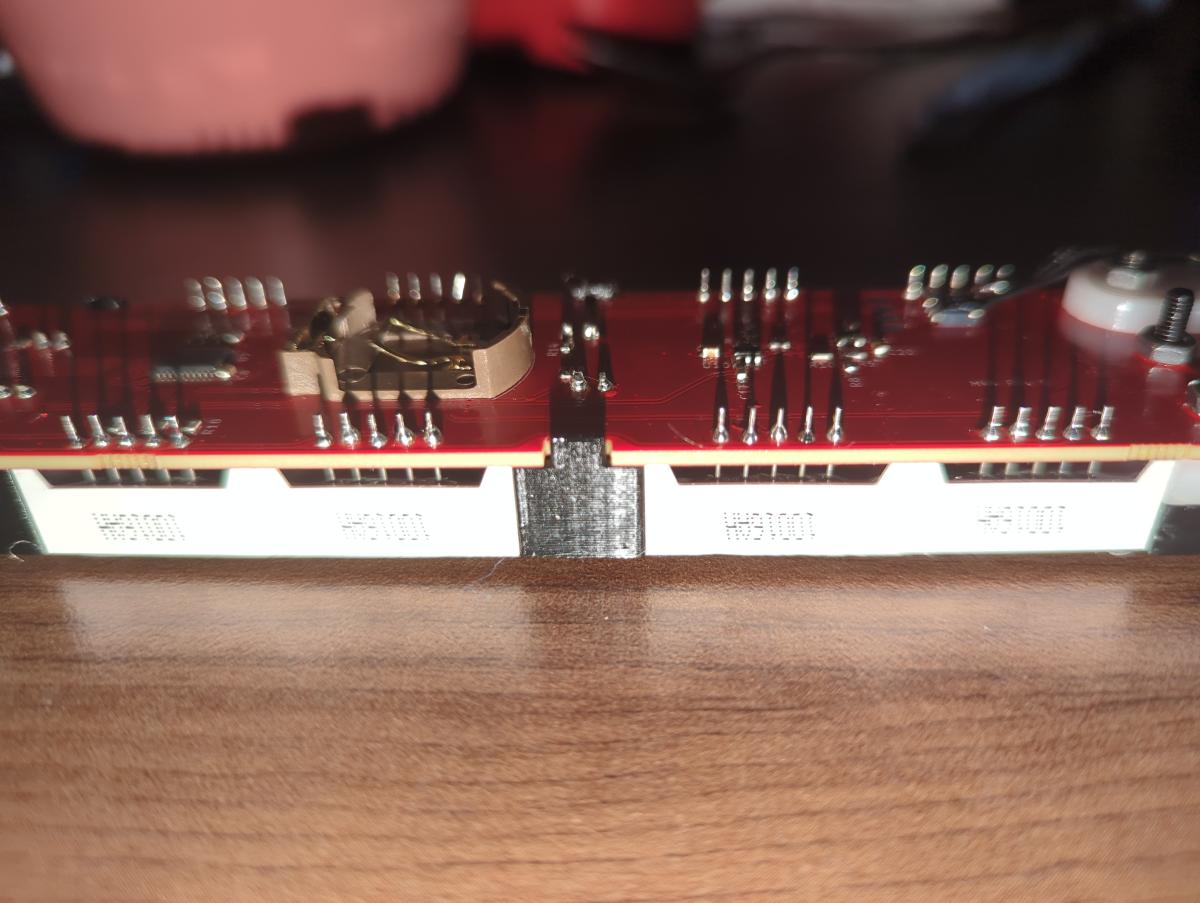 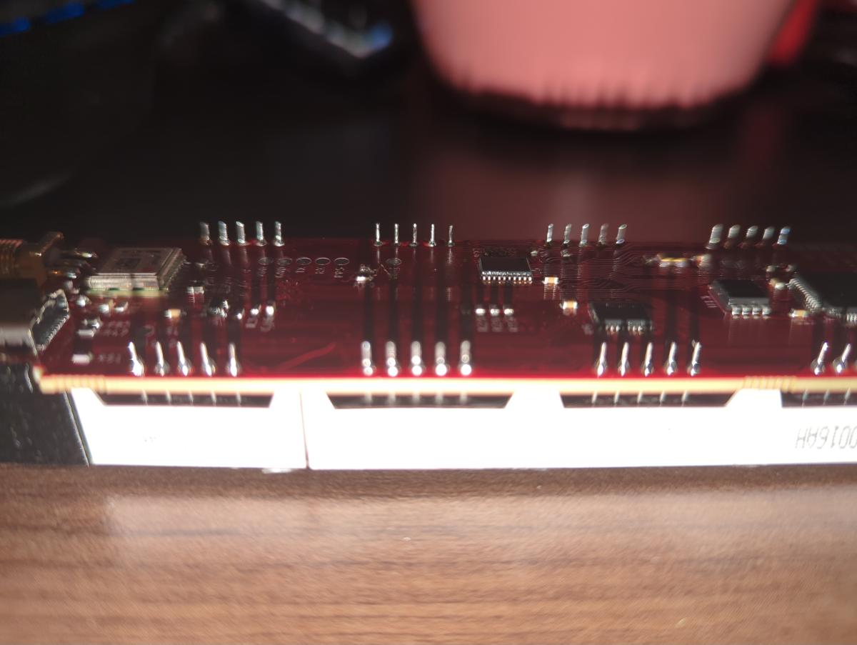 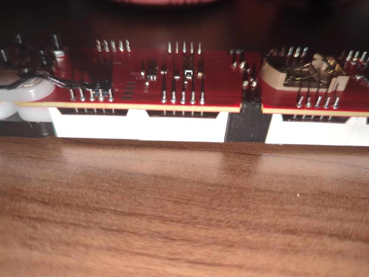 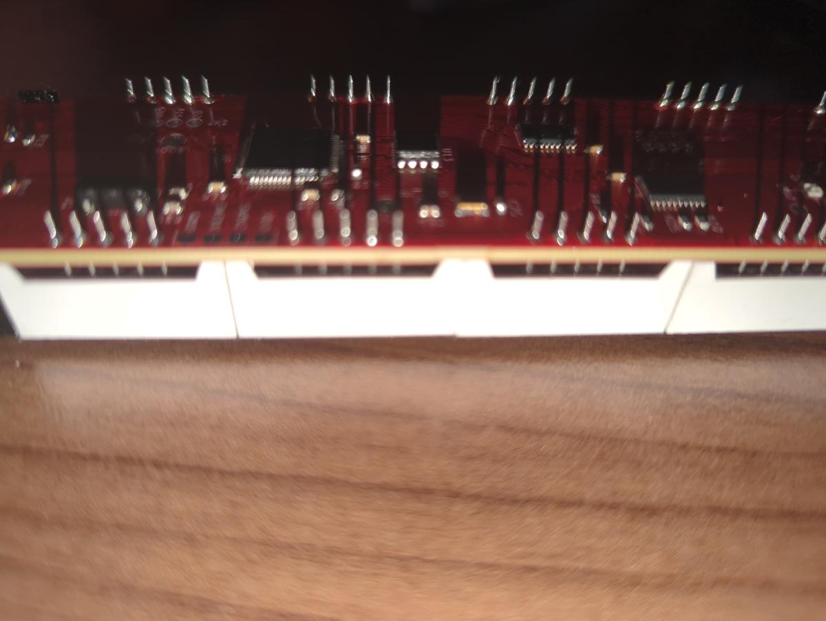 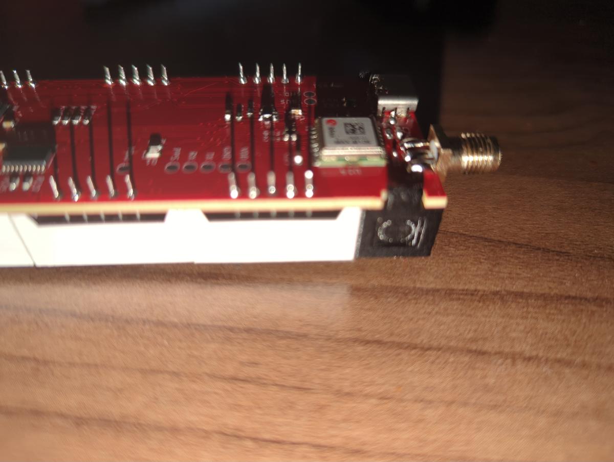 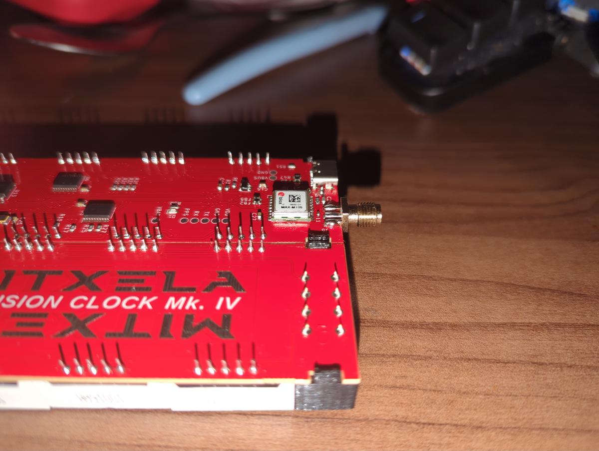 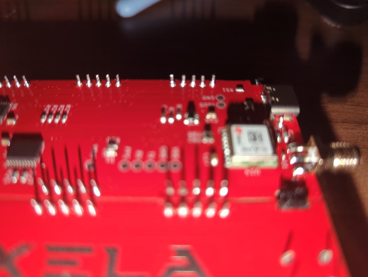 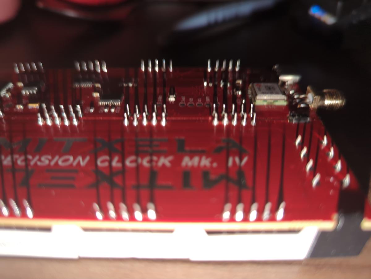 ------------- |
| [top] | |
| mit | Posted: 7 May 2026, 11:59 AM |
 yeah whatever Admin Posts: 687 Joined: 4-May 16 |
I've not seen that behaviour before, it might take me a while to think what could be causing it. The soldering looks fine, at least the parts I can make out. Could you maybe take another picture of the legs of the light sensor? It is of course very close to the USB port, just check there isn't a short there. The fact you were able to get it to show d2 Error says the display is working, but if it then freezes with just single digits showing, that suggests the processor has stopped and the DMA has stopped as well. Hmm. Do you notice any parts of the clock heating up? Does the USB port still work? When you plug it into a computer does it appear as a storage device? ------------- |
| [top] | |
| mit | Posted: 7 May 2026, 12:12 PM |
|
yeah whatever Admin Posts: 687 Joined: 4-May 16 |
Upon thinking about it, I'm pretty sure it might be a short on VDD, most likely where the leg of the light sensor is near the USB port. Here is the VDD track: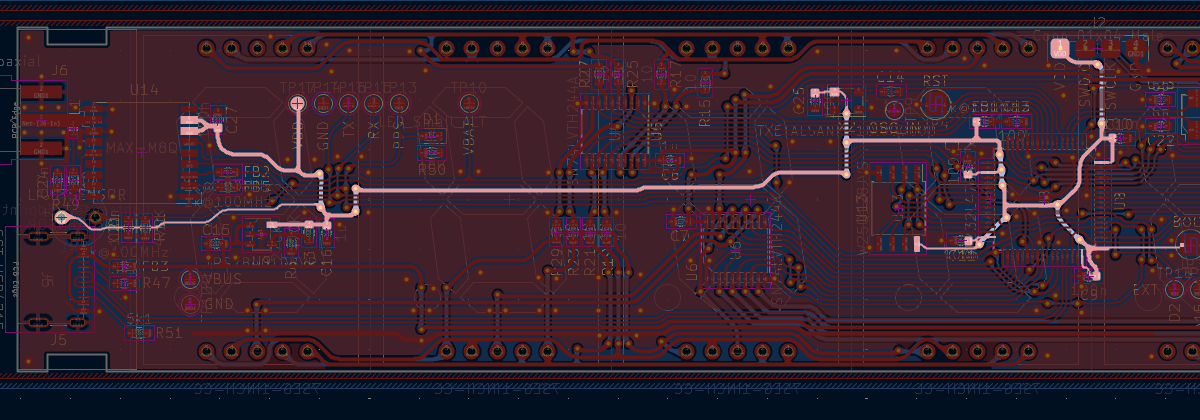 It's supposed to be 3.3V, you could check it with a multimeter at the test pad at the top if you have one (probe VDD and GND). I suspect the regulator U9 will be getting hot. The display itself is powered from a separate regulator, which is why it's still lit up but the matrix has stopped. The main processor will work down to 1.8V, so maybe it is limping along when first powered up but then cuts out when more power is drawn. ------------- |
| [top] | |
| Loading_M_ | Posted: 7 May 2026, 12:37 PM |
|
Member Posts: 12 Joined: 7-May 26 |
First - the clock has never been recognized by my pc as a USB device. Second, the behavior has changed after letting it sit overnight. The display now flickers the center segment of less significant minutes digit. When I woke up, it was a weak flicker, but now it's a brighter light. I'm also seeing the D1 led light up periodically. For voltages: - VBus is ~5V (I assume it's the USB voltage pin, so that looks good) - VDD is ~2.7V (which is low, but it sounds like it should be in-spec) I haven't noticed U9 (or any part of the board getting warm, but I also haven't left it plugged in for an extended period of time. This is the best image of the light sensor pins I was able to take. From what I can tell, I don't think it's shorted to any nearby components? The resistance to ground and between the legs if pretty high. 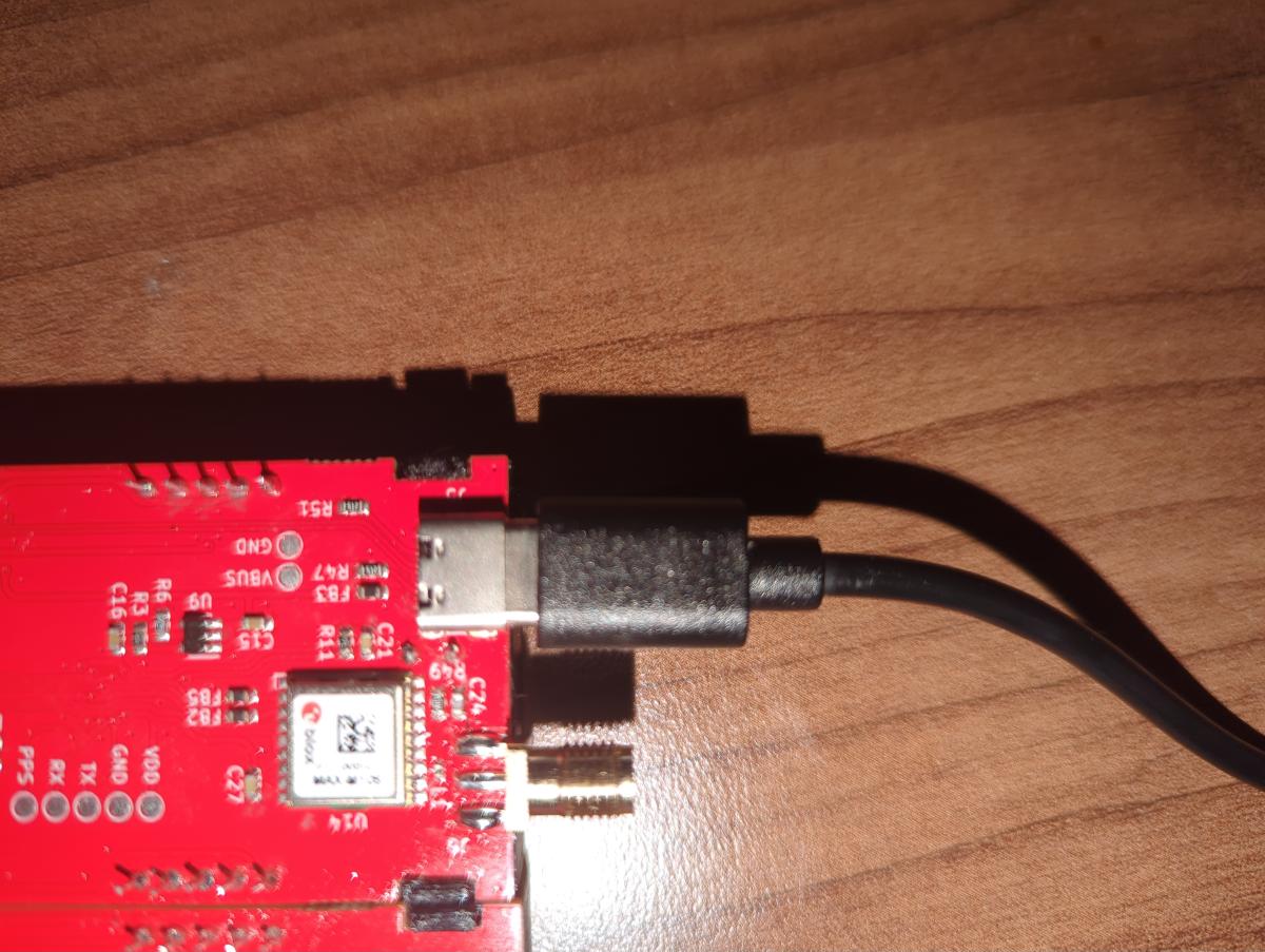 ------------- |
| [top] | |
| Loading_M_ | Posted: 7 May 2026, 12:49 PM |
|
Member Posts: 12 Joined: 7-May 26 |
One minor update: after leaving it plugged in for a little while, the display has changed. More segments in the minutes place started flickering with the center, and two segments on the date side have lit up.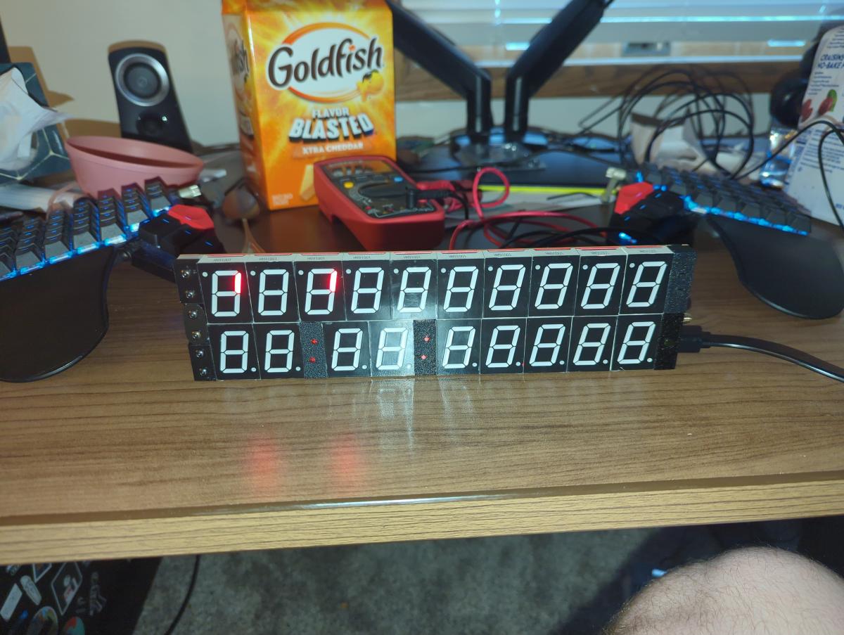 Since I started writing this comment, the segments in the date side have changed again. 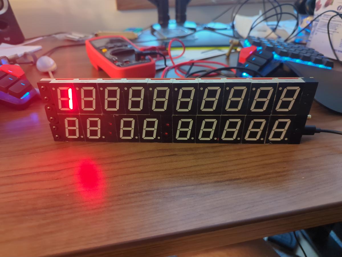 ------------- |
| [top] | |
| Loading_M_ | Posted: 7 May 2026, 01:26 PM |
|
Member Posts: 12 Joined: 7-May 26 |
After leaving the clocked powered for a while, the segments on the date side that have been lit up are flickering and the lower minutes digit also occasionally flickers. As a side note, I do also have access to an oscilloscope if that would provide useful information. ------------- |
| [top] | |
| mit | Posted: 7 May 2026, 01:28 PM |
|
yeah whatever Admin Posts: 687 Joined: 4-May 16 |
Yes the light sensor looks fine, sorry. But VDD voltage is definitely not right. The flickering you are seeing is probably just the inputs to the display drivers floating. It is interesting that the date side is lighting up as well. You'll have to be patient while I think about what's going on here... The 2.7V your multimeter measured might actually be filtered and in reality it's flickering on and off quickly. It's not impossible there's a mistake on the surface mount soldering, but I do test the boards before sending them. If VDD was shorted to ground U9 would get hot quite quickly, it's probably not that. For the clock to get as far as displaying "d2 Error" the firmware must be flashed correctly. It wouldn't hurt to also check the soldering on the hall sensor on the date side, though this is less prone to problems on Rev D. As you've got the multimeter, can you also check the voltage on the date side - it is labelled VDD as well but the date has a separate regulator. The date side's voltage should read about 3.0V, though it varies from 1.8V to 3.6V when the brightness circuit is running. The time side's VDD pad should always be 3.3V under normal conditions. Just to double-check, when you measured VDD, that 2.7V was on the time side, correct? ------------- |
| [top] | |
| Loading_M_ | Posted: 7 May 2026, 04:23 PM |
|
Member Posts: 12 Joined: 7-May 26 |
I hadn't considered the possibility of the display drivers floating, but that would explain most of the behavior. I did check the date side voltage, and it measures very slightly lower than the 2.7v on the time side. Also, if I'm remembering correctly, the time side had risen a bit to closer to 2.9 or 3 volts. I'll pull out the oscilloscope this afternoon once I get home from work, and see whether the voltage is consistent or not. ------------- |
| [top] | |
| Loading_M_ | Posted: 7 May 2026, 10:13 PM |
|
Member Posts: 12 Joined: 7-May 26 |
I've now had a chance to look at the voltage with my oscilloscope, and it's looking pretty stable. It also appears to be 3.1 to 3.2 V now, which is interesting. I also probed the TX and RX pads, and it looks like TX is seeing some pretty normal looking traffic (relatively clean level transitions - it's clear some data is being transmitted), but the RX line is a mess. Clean TX: 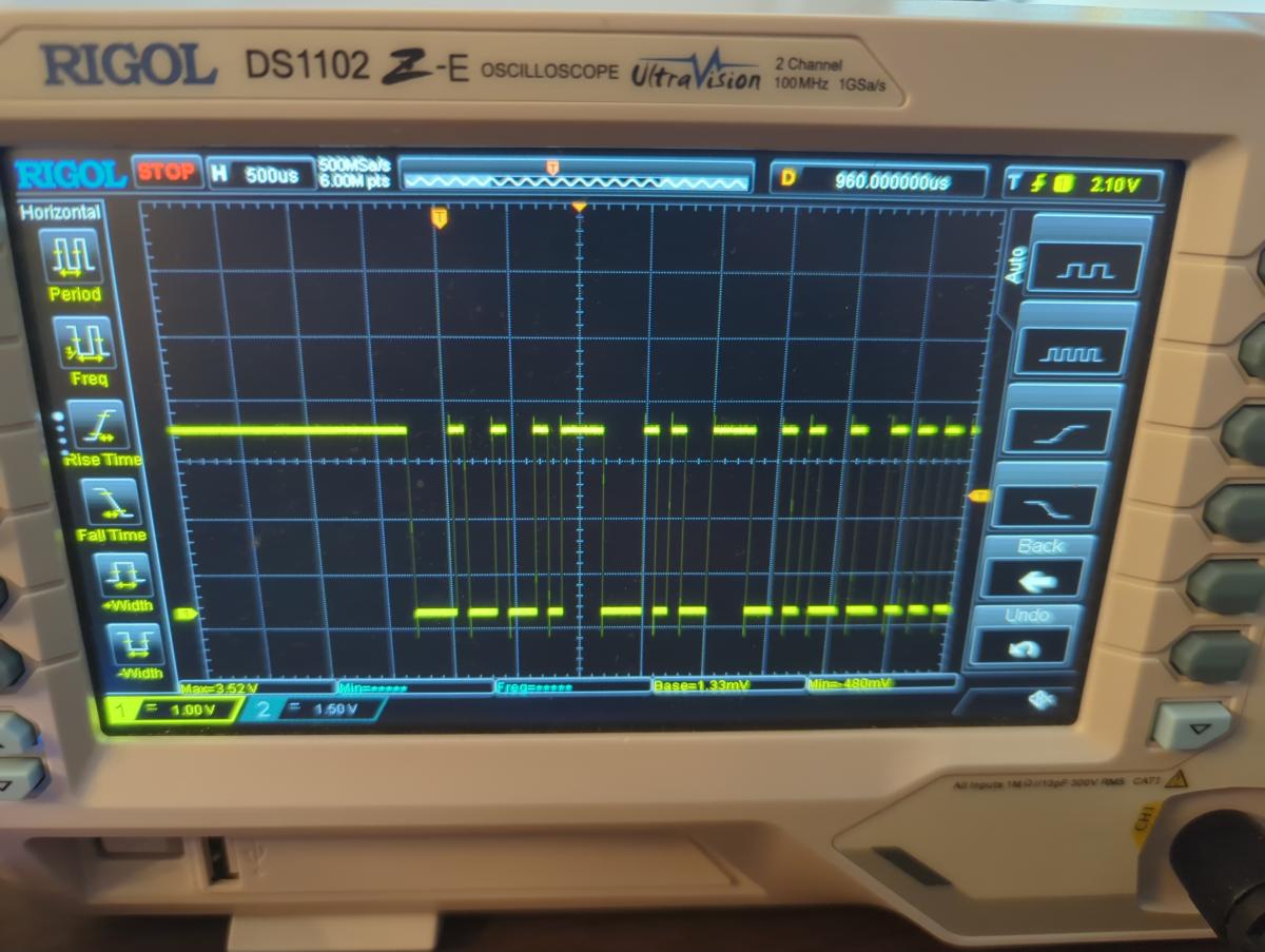 Messy RX: 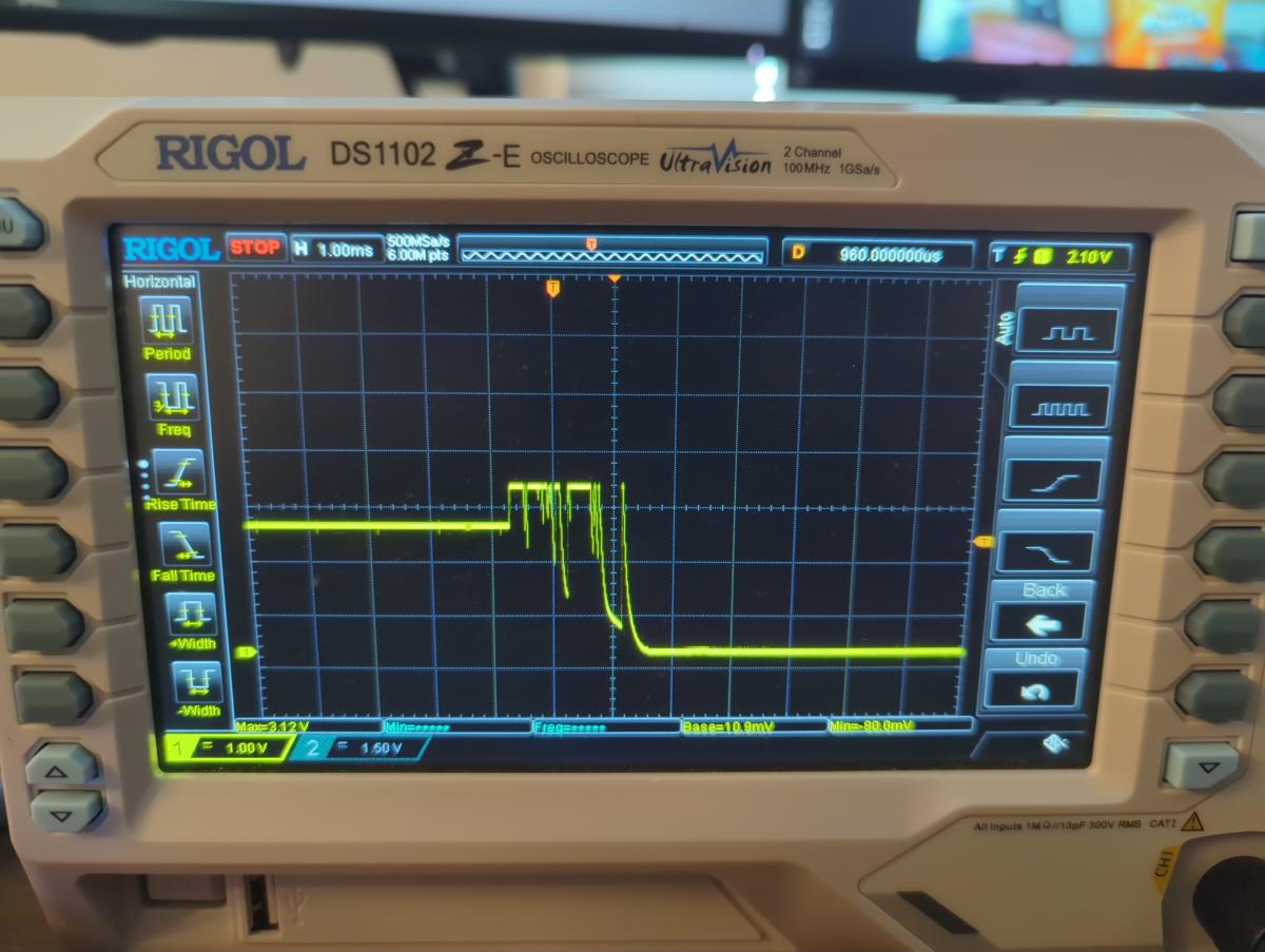 ------------- |
| [top] | |
| mit | Posted: 8 May 2026, 06:52 PM |
|
yeah whatever Admin Posts: 687 Joined: 4-May 16 |
I'm still not sure what it could be. If I had the clock here, my next step would be to look at the circuit board under the microscope for any possible shorts or damage. I also have the luxury of a thermal camera here, which is very useful for spotting shorts... Here are some more ideas while I think about it: - Are you able to measure the current draw? There are USB monitoring devices which can tell you this. It's also possible with the multimeter but you'd need to wire up 5V into the VBUS and GND pins. The clock shouldn't draw more than 600mA at max brightness, and much less than that if the display is mostly off. - Try powering it on without the date attached again, does it still give a d2 error even briefly? - Try powering it on while covering the light sensor, does that affect anything? - Continuity test the legs of the colon LEDs, check they're not shorted - With the oscilloscope, probe the VDD pad on the time side while powering on the clock. Does it immediately jump to a stable voltage? On a working clock it should be exactly 3.29V I am wondering if maybe the U9 regulator did overheat, and then has shut down in a failure mode, and the VDD line is being back-fed from one of the other regulators via one of the processor's GPIO pins. Given that the other two regulators are controlled by the DAC on the main processor, it would lead to all kinds of weirdness. If you have a power supply that can give 3.3V, it might be worth trying to feed 3.3V into the VDD on the time side and seeing what happens. The safest way to do this is to power it via the USB first, connect the ground of the power supply to the clock's ground (a crocodile clip onto the USB or antenna connector will work) and then carefully touch the VDD pad with the other lead. Can I also ask just to check, I know I added a bit in the instructions about the light sensor legs, how you can bend them to allow it to be pulled forwards later if needed, did you attempt that, and is it possible the legs touched something else even briefly? I wouldn't normally say this but you're also welcome to post the clock back to me and I can repair it here, if this back and forth becomes too tedious. ------------- |
| [top] | |
| Loading_M_ | Posted: 8 May 2026, 07:31 PM |
|
Member Posts: 12 Joined: 7-May 26 |
Well, if U9 hadn't failed, it's probably short now. When I applied 3.3 V to the VDD rail, U9 started heating up quite a bit. (I've now got a tiny burn on my finger...) My guess is I overheated something near U9 when soldering either the digit or the light sensor nearby. Weirdly enough, the other troubleshooting I did didn't show any power supply issues. The power draw looked like it's in range, between 300 and 400 mA as measured by my variable voltage supply. Since the one time it did give a d2 error, it hasn't given one since, even when the date side is detached. The light sensor should be fine, several of my tests were conducted when covering the sensor, and I did not attempt to leave myself any extra distance in the legs. Likewise, the LEDs look fine, and aren't shorted. According to the oscilloscope, VDD showed what I expect a healthy supply to do. The rise time was ~35ns, which I assume is pretty normal, and it didn't seem to flicker afterward. It did only rise to ~3.22-3.24, but that's the only weird thing. ------------- |
| [top] | |
| mit | Posted: 8 May 2026, 11:53 PM |
|
yeah whatever Admin Posts: 687 Joined: 4-May 16 |
Eeep, sorry about that. Is it possible there is damage to either of the resistors R3 and R6 next to U9? They are the feedback resistors that control the output voltage of U9. I am not sure it's possible to measure them with the multimeter while they're soldered down though as other components will interfere with the measurement. 300-400mA is still higher than expected if the display is mostly blank. With only a few segments lit it would normally be under 100mA, so there may still be a short or failed component somewhere else. ------------- |
| [top] | |
| mit | Posted: 12 May 2026, 01:45 AM |
|
yeah whatever Admin Posts: 687 Joined: 4-May 16 |
While flashing and testing the last batch of circuit boards, I had one that failed to boot and put it aside for investigation later. I just took another look at it, the symptom was that it failed to power up at all, with VDD reaching about 2V due to a short somewhere. A quick look with the thermal camera showed hot spots on U9 and X2, the TCXO. With the hot air gun I removed X2, cleaned the pads and soldered a new one in place. The board then powered up normally, flashed correctly and works fine. Worth noting that the regulator U9 did not need replacement. The part number for it on Rev D boards is TPS78401DBVR, and the datasheet states its thermal shutdown is at 170C, which seem very hot, but is apparently a safe shutdown temperature. So it's possible the regulator on your clock is still OK. I can't be certain but in my experience when these sot-23 regulators blow for good, they visibly release smoke. More interesting is why on this board X2 was shorted. It's possible it was a subtle soldering error during reflow, but visually it looked fine even after desoldering. I have heard that TCXOs are particularly sensitive to vibration (you are not supposed to clean boards with them ultrasonically). On your clock, if it was the TCXO that failed, it wouldn't have ever got as far as d2 Error, it also wouldn't have flashed correctly before sending it. But maybe it was an intermittent connection? Out of interest I took the failed TCXO here to the microscope and carefully peeled open the can with a razor blade. 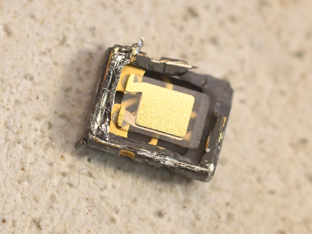 The crystal is held on with some kind of conductive glue. The die is underneath. I was expecting gold bond wires that might have snapped, but carefully lifting up the crystal revealed a rather boring surface mounted die. 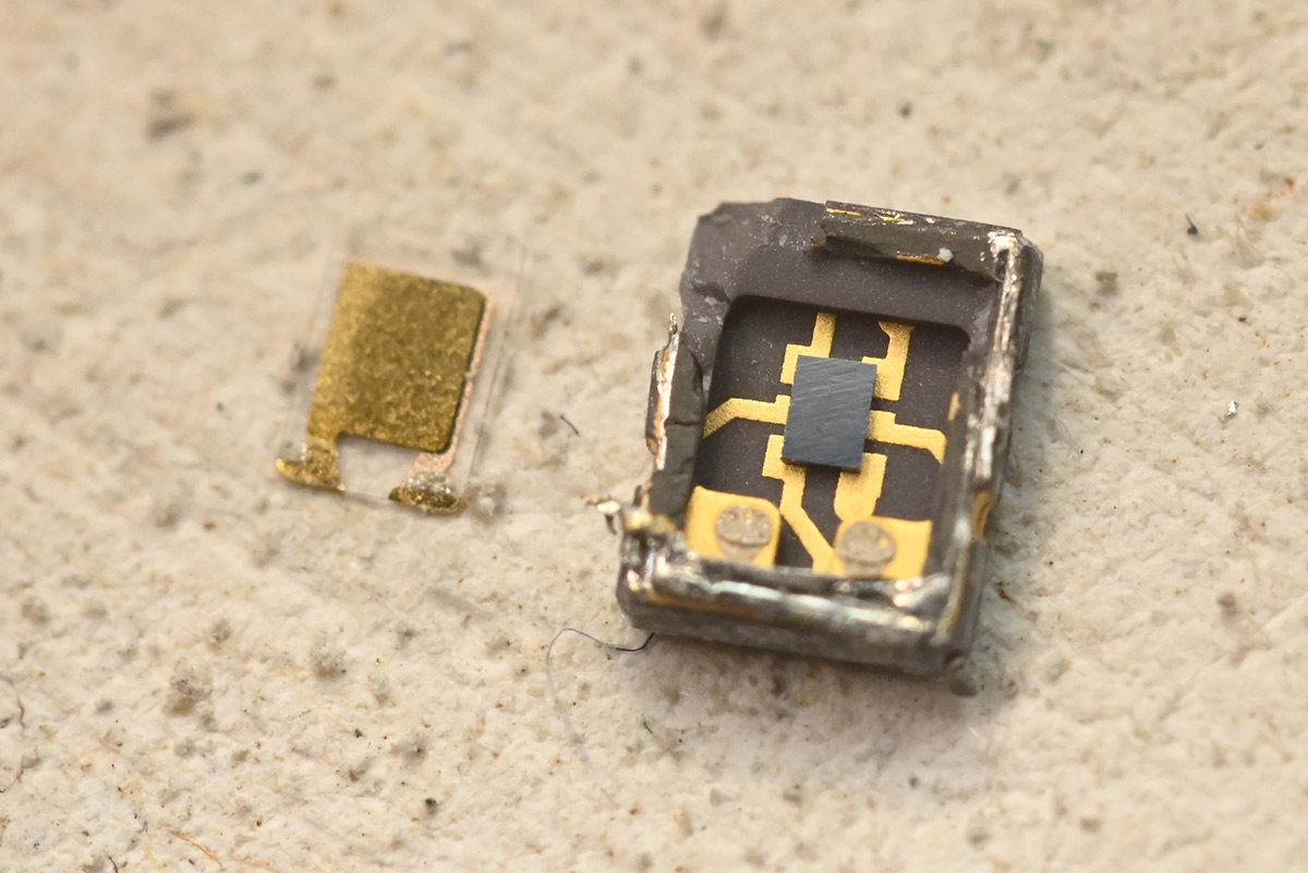 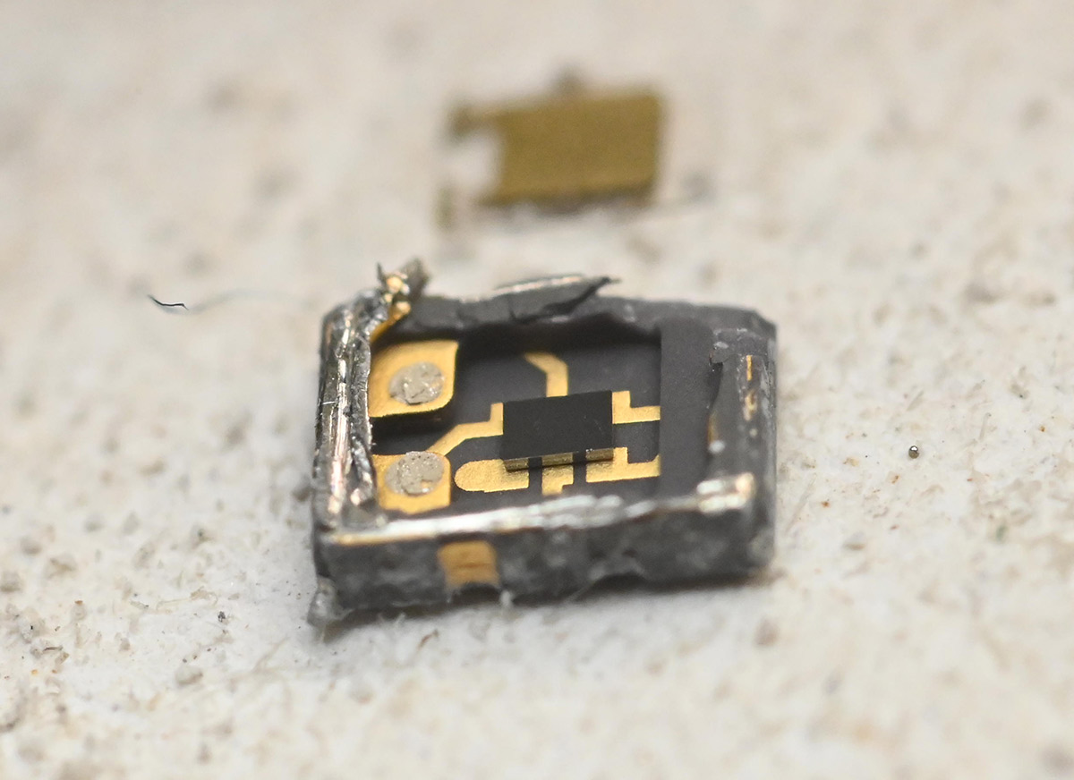 The die cracked as I lifted it out, some nice iridescent colours on the underside but no clear sign of what failed. I could do with a higher power microscope... 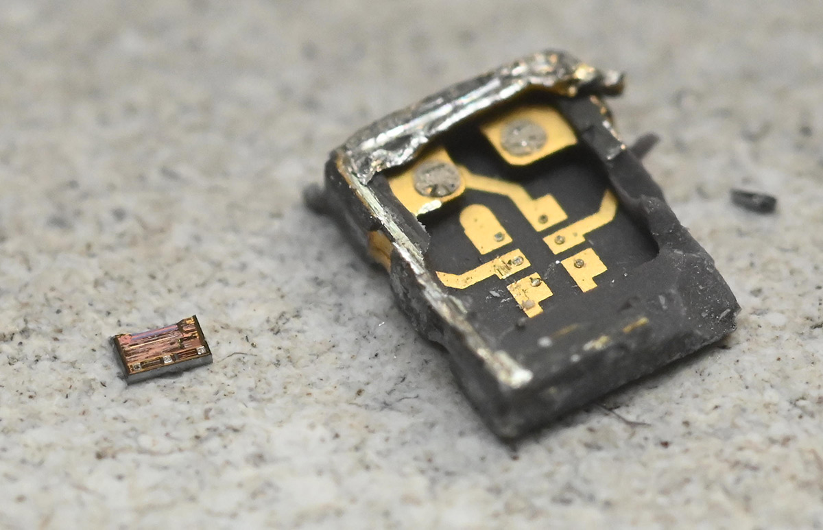 That probably doesn't get us any closer to fixing your clock, but it was an interesting diversion. ------------- |
| [top] | |
| Loading_M_ | Posted: 12 May 2026, 01:48 AM |
|
Member Posts: 12 Joined: 7-May 26 |
Well, good(?) news! I went to my parent's house over the weekend, and just got a chance to do some more testing today. It's mostly working now. The time and date display correctly, it shows up when plugged into my PC, and it's able to get a GPS fix on my location. The only issue now is that some of the segments are flickering or dimming. Taking some resistance measurements for the affected segments, it looks like I might have damaged the LED segments, since some of them have a much lower resistance than others. I'm guessing that this was the core issue before - they aren't quite failed short, but probably overheated.  I'm assuming if I de-solder the affected digits and replace them it should solve the issue for good. I'm happy to pay for replacement parts, or look for somewhere to source replacements if you can provide specs. ------------- |
| [top] | |
| mit | Posted: 12 May 2026, 01:46 PM |
|
yeah whatever Admin Posts: 687 Joined: 4-May 16 |
Interesting. It's possible, if there was a short somewhere, that when you powered it from the bench supply, it fixed the short by blowing it like a fuse. If you need replacement digits it's best if I send you some from my supply here, as there are tiny differences between batches so they might not match otherwise. However from that picture it looks like all the same segments in matrix groups are affected. I would double-check that it's the segments that have failed and not something in the driver. It's best to use the diode-tester mode of the multimeter rather than resistance, touch the black probe to the centre pin and poke the other pins with the red probe. They should light up, and the meter should read about 1.8V. If needed I did write a little tutorial on how to replace digits here ------------- |
| [top] | |
Sign in to post a reply.