
| Paradox | Posted: 2 Mar 2023, 06:24 AM |
|---|---|
 Member Posts: 16 Joined: 2-March 23 |
Still finishing the assembly of the clock, Gorilla Glue superglue doesn't seem to bond wood, so I'm gonna try a different glue tomorrow. Turned on the clock for a test, sans colons, and the date part of the display is always full-bright. 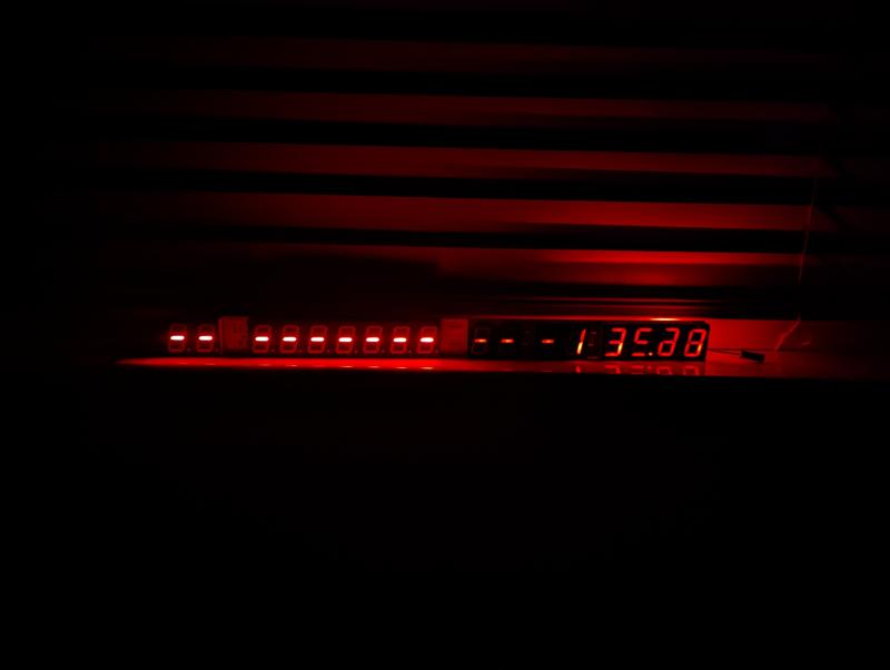 Looking through the forum, I see others who had this issue seem to have problems with the joint for one of the transistors. I desoldered the decade digit, and checked the joints, and they appear fine. 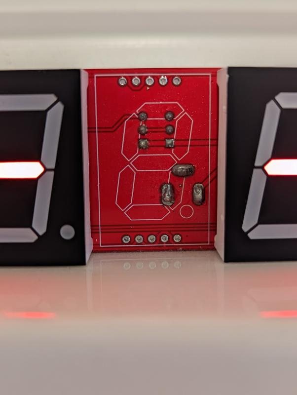 Also noticed one digit, the seconds ones digit, has issues with its C segment. It appears to flicker very dimly. I was going to swap it with one of the hyphen digits. Finally, I've noticed the dst indicator appears to flicker at the same frequency the centisecond digits flicke. Is this expected? Thanks! ---- Update: I've let it run for about half an hour, and the D segment of everydigit flashes when normally illuminated. When that segment is supposed to be off, such as on a 7, it does not flash. All other digits will occasionally flash quickly, but not strobe ---- Update 2: I saw the advice in this thread, to test the segments using a bench power supply. I ran my power supply at 2v, and all segments on the 1 second digit illuminate properly. Last edit by Paradox at 2 Mar 2023, 07:05 AM ------------- |
| [top] | |
| mit | Posted: 2 Mar 2023, 12:35 PM |
 yeah whatever Admin Posts: 687 Joined: 4-May 16 |
Good job desoldering the digit cleanly, the transistor soldering looks fine. It probably is a soldering mistake somewhere though. The most common problems are shorts between two pins, or dry joints where the pin isn't soldered. This may sound obvious, but it has caused problems in the past - are you sure the transistors are the correct orientation? No, the DST indicators (or the D segments) shouldn't be flickering. It's possible both problems are related, but I'd suggest fixing the brightness mismatch first. Try following the I_SET signals going from the transistors to the display driver chips. If there is a short from one of those to another signal that would definitely disrupt things. Hopefully you've already found the interactive board diagram. A photo of the component side of the clock could be helpful for me to spot any other problems. I should also add, if this kit is a very recent one, I added a "display test" mode at the end of January 2023. It's less useful than it sounds, I haven't documented it yet, but if you power on the clock while shorting PD5 to ground it will illuminate all the segments. PD5 is Pin 9 of the chip, pin 10 is a ground pin, so you can just short them together with a screwdriver or something. However, illuminating all the digits at once won't show all possible problems, e.g. if there's a short between two segments on a digit they'll both illuminate as if there's no problem. ------------- |
| [top] | |
| Paradox | Posted: 2 Mar 2023, 05:48 PM |
|
Member Posts: 16 Joined: 2-March 23 |
Desoldering isn't a problem, years ago I purchased a Hakko FR-300 desolder-er, which has been invaluable ever since! I just checked all the nets on the tester, and they all had continuity across them, both to the pads and the components soldered into the pads. I removed the displays that are over various parts of the brightness system, hoping to see a shoddy weld or similar, but I didn't see anything that looks bad. I've attached a few photos, in case I missed something. 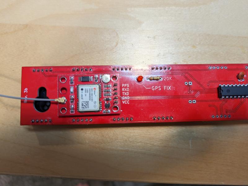 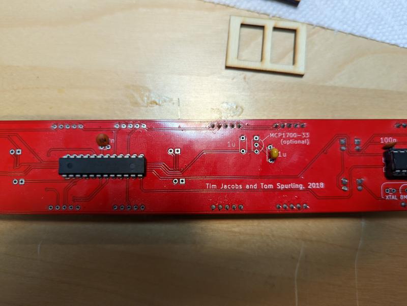 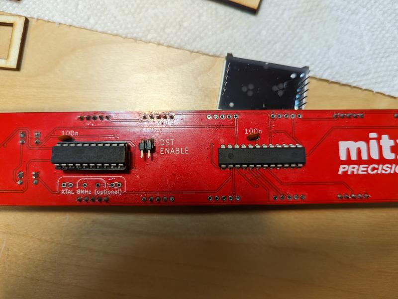 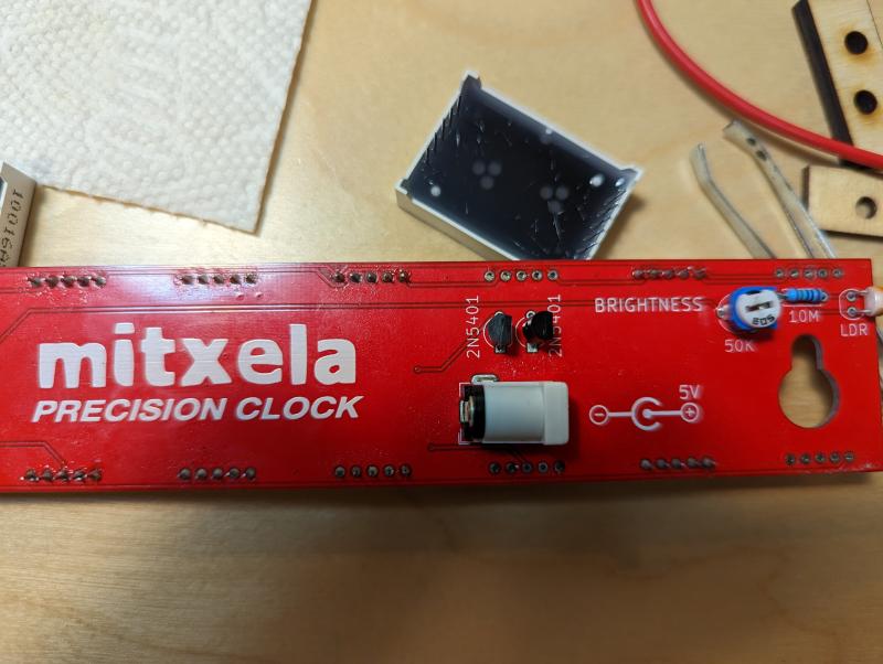 And here's where the other displays were removed 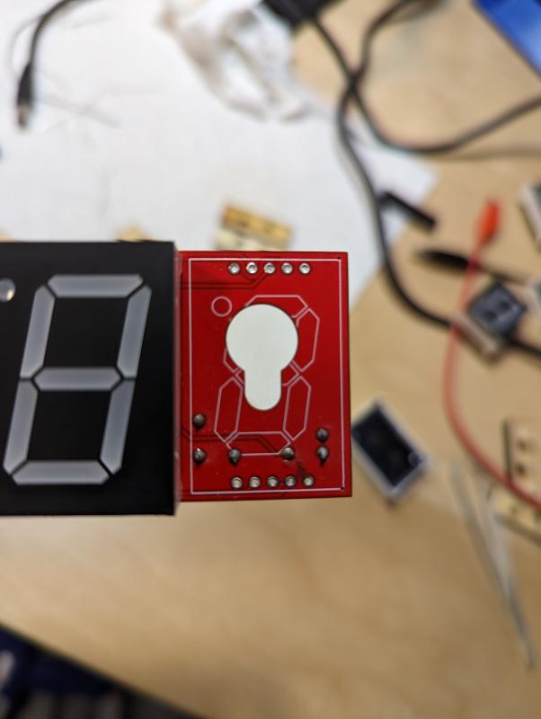 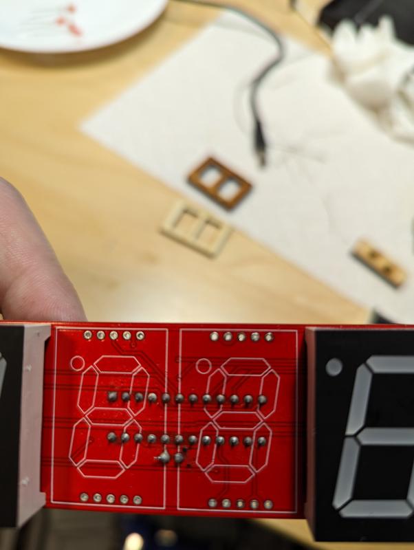 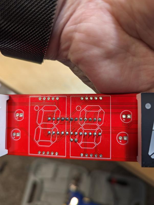 If the images are too low resolution, or you'd like to focus on a particular area, I can take or link better versions Last edit by Paradox at 2 Mar 2023, 05:51 PM ------------- |
| [top] | |
| mit | Posted: 2 Mar 2023, 10:00 PM |
|
yeah whatever Admin Posts: 687 Joined: 4-May 16 |
That mostly looks fine. There is a small smudge of flux residue in this image: I would suggest cleaning it with flux cleaner, it can't hurt. It also appears to be next to the ISET pin, so if there is a short or partial connection there, it would explain the brightness difference. ------------- |
| [top] | |
| Paradox | Posted: 3 Mar 2023, 05:40 AM |
|
Member Posts: 16 Joined: 2-March 23 |
I took all the displays off, and gave the board a reasonable cleaning. There wasn't too much flux residue, but there was some. In doing so, I noticed one of the 100nF caps looked slightly damaged, as if it had blown itself (black speck on the board next to it). Specifically, the cap that sits just next to the ATTINY. Removing it and testing it on my multimeter shows it as faulty, barely getting a few nanofarads of capacitance Its too late now, but tomorrow morning I'll run to Radio Shack (I'm fortunate to still have one!) and see if I can pick up a new cap. Other than the brightness/flickering issues that I've mentioned in this thread, the board does work. It was able to grab a GPS signal in my basement and display accurate time. 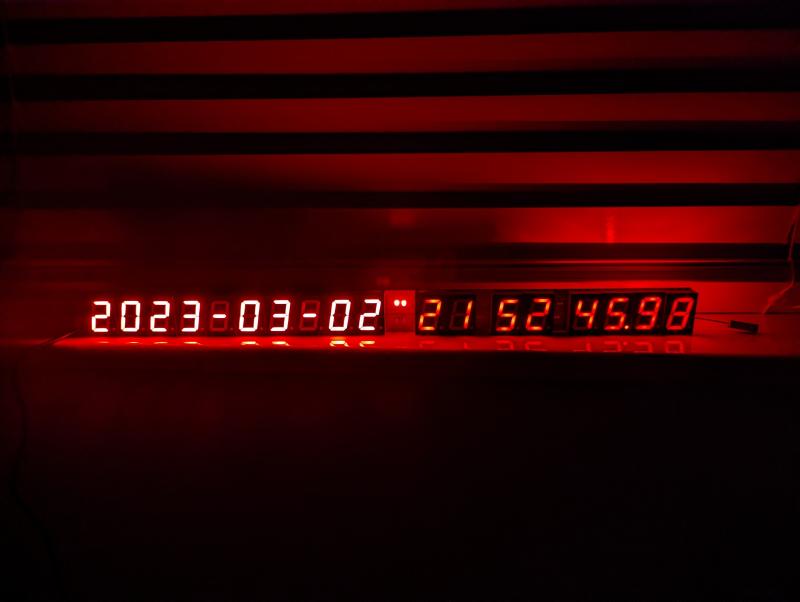 ------------- |
| [top] | |
| mit | Posted: 3 Mar 2023, 11:49 AM |
|
yeah whatever Admin Posts: 687 Joined: 4-May 16 |
Has the flickering/segment issue resolved itself? While replacing the capacitor is worthwhile, it won't be the cause of the brightness problems. I would instead next look at the two transistors - it's possible one of them is damaged or mis-manufactured. If you have a multimeter that can measure hFE (sometimes they have a little socket to plug transistors into) you could desolder the transistors and test them. They are from the same batch, but if there was a massive difference in their current gain that would manifest as a difference in brightness. I test every display driver chip before sending it, so the maxim chips should be fine. I don't normally bother to test the transistors but I've never had it be a problem before. ------------- |
| [top] | |
| Paradox | Posted: 3 Mar 2023, 08:48 PM |
|
Member Posts: 16 Joined: 2-March 23 |
Radio Shack didn't have any of the transistors I needed in stock, but they did have the caps, so I've replaced the cap that was damaged, and ordered the transistors, with 1 day delivery. Given that the package sat in a UK port for a week, due to the cyberattack, who knows what happened during shipping. Unsurprisingly replacing the cap had no effect on the flickering and dimming issues. The segment of the seconds digit that was flickering before, however, is more stable, it now flickers with all the other digits instead of independently I'll post an update when I get them and if it fixes the issue Thanks! Last edit by Paradox at 3 Mar 2023, 08:56 PM ------------- |
| [top] | |
| mit | Posted: 4 Mar 2023, 10:11 AM |
|
yeah whatever Admin Posts: 687 Joined: 4-May 16 |
For what it's worth, I just tested 20 transistors from my supply and they were all within a few percent of the same value. Perhaps, when you have the transistors removed, you could poke around with a multimeter some more. You could measure the resistance between each ISET pin and ground. It might give a clue to whether one of them has a short somewhere. You could also measure the resistance of the LDR, this will depend on the light levels but it should be from a few kOhms, up to a few hundred kOhms or more in the dark. Just as long as it's not measuring as a short. ------------- |
| [top] | |
| Paradox | Posted: 7 Mar 2023, 03:16 AM |
|
Member Posts: 16 Joined: 2-March 23 |
I checked the ISET pins, and they seem to be in order. Frustratingly, when I put the thing back together, and plugged it on, a different problem has manifested. Now three digits seem to be intermittently misbehaving. The Year ones digit either has all segments illuminate, or the segments required to indicate 3 illuminate properly, with the remaining 2 segments flickering dimly. 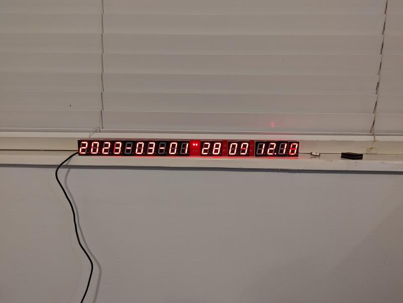 The day ones segment is alternating between displaying March 1st and the 6th (as of this writing), but preferring to display Mar 1st. The Minute ones segment is acting similar to the year ones digit, except its far more stable in that it prefers to display all segments (except the decimal point) as lit. Very occasionally, the DST indicator will briefly illuminate, before going dark again. The standard indicator is continuously illuminated, without issue. Finger-checking the temperature of the driver chips, they are both quite hot, unpleasant to touch after about 5 seconds. The date driver chip is hotter than the time driver chip. Finally, while the display doesn't appear to react to any changes to the POT for brightness, nor to changes in the ambient lighting (from the RDM) it is no longer flickering (aside from the singular digit issues mentioned) I worry that I might be breaking more things than I'm fixing haha. I'm not a novice to soldering; I've built several computer keyboards, some with SFP components, but I'm not an expert in it either. I'm probably falling into the dangerous chasm of "know enough to get in trouble but not out." Thank you for your patience with me on this! ---- Update: Right as I submitted the post, I looked over at the clock, and now the date segment was displaying gibberish, and then went completely out. Last edit by Paradox at 7 Mar 2023, 03:17 AM ------------- |
| [top] | |
| mit | Posted: 7 Mar 2023, 11:15 AM |
|
yeah whatever Admin Posts: 687 Joined: 4-May 16 |
QUOTE (Paradox)
Finger-checking the temperature of the driver chips, they are both quite hot, unpleasant to touch after about 5 seconds. The date driver chip is hotter than the time driver chip. Oh dear! That's usually a sign that you should cut the power, the parts definitely shouldn't be getting hot. I have a feeling the display driver for the date side may now be damaged. They're usually pretty hardy but if it was left on in that state and then suddenly went out, that doesn't bode well. Before you do anything else, let's just look over what we've determined so far. You say the ISET pins seem to be in order, what did you check about them? From the symptoms this still sounds to me like there was some leak between VCC and ISET_DATE. I didn't fully explain what I meant before. A multimeter measures resistance by injecting a small current and measuring the voltage. Since we're looking at semiconductors instead of resistors, the order of the probes will matter. What you might also find is that while the meter auto-ranges, it adjusts the current it applies. I was hoping that a short would be obvious, but even on a working clock the measurements can be difficult to interpret, as it will depend on the excitation current. Meters usually also have a diode tester mode, that reads out the voltage (and will normally reach a higher voltage that ohmmeter mode). On my clock here, with my meter, and the clock turned off, here's what I measure: In ohmmeter mode, red probe to ISET and black probe to ground, it reads about 40 megaohms, continuously rising as it charges a capacitor, and after a few seconds reads overload. I can discharge it by connecting black probe to ISET and red probe to VCC. In both cases, we're talking tens of megaohms or more, most likely as the applied voltage isn't high enough. But if there was an ohmic short, it would show up here. In ohmmeter mode with red probe to VCC and black probe to ISET, on the time side I see the same capacitance input thing, but on the date side I see a fixed resistance of around 10 megaohms that varies as I cover the light sensor. In diode tester mode, with red probe to either ISET and black probe to ground, I read about 1.85V. While we're at it you might as well measure the resistance of the components of the light sensor circuit, the trimpot should read 50K from one end terminal to the other, and if the knob is centred then about 25K from the middle pin to an end pin. I don't suppose you took any pictures of the board after cleaning the joints? Particularly the underside of the date display chip, where I pointed out the potential problem. Some close up pictures of the top of it from a few angles would also be helpful. Before you replace any more parts, let's try and find the problem, or you may just solder new parts in for it to still not work. ------------- |
| [top] | |
| Paradox | Posted: 7 Mar 2023, 06:39 PM |
|
Member Posts: 16 Joined: 2-March 23 |
I got some fresh pictures of the 3 ICs solder joints. From left to right, facing the front (display side) of the clock 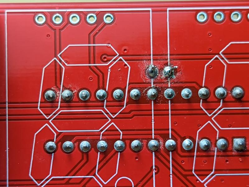 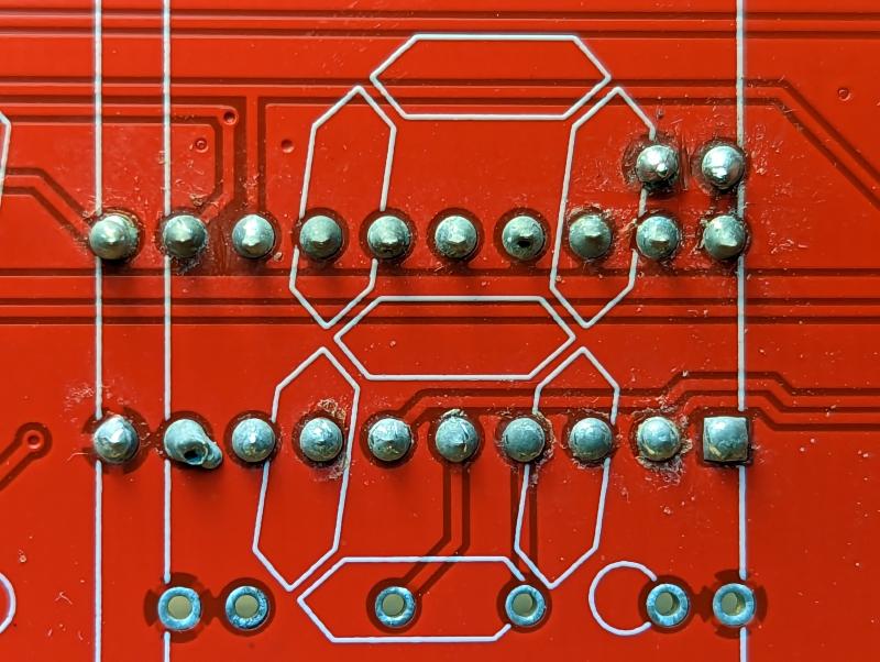 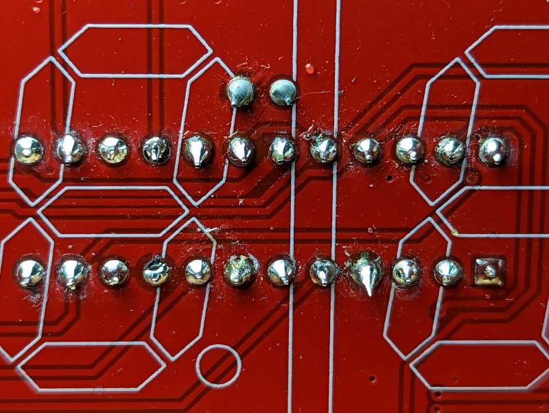 When connecting red probe to ISET_DATE and black to the GND on the power connector, I do get a slowly rising resistance, but when my ohmmeter is set to megaohms (with auto ranging turned off) it remains in the area of 0.5MΩ Testing ISET_TIME in the same manner hovers around 1 MΩ In diode tester mode, both ISET pins read 1.5v The pot displays 41kΩ across the two fixed legs, and between 40kΩ-4Ω across a fixed leg and the wiper. The 10MΩ resistor is pretty close to 10MΩ The RDM seems to range from around 6kΩ to as high as 52kΩ If its at all useful, I have a scope and a bench power supply, in addition to my multimeter. I could use them to take any measurements you need to help me sort this ------------- |
| [top] | |
| mit | Posted: 8 Mar 2023, 09:04 PM |
|
yeah whatever Admin Posts: 687 Joined: 4-May 16 |
Those look fine, how do the parts look from the top side? Can I also ask what temperature the soldering iron was set to? I assume at this point, powering it on doesn't light up the date side, or was that just a temporary effect? But if it starts to get hot turn it off. Another question, what power supply are you using? What's the current capacity, and can you check the voltage with the multimeter? ------------- |
| [top] | |
| Paradox | Posted: 9 Mar 2023, 04:55 AM |
|
Member Posts: 16 Joined: 2-March 23 |
Here's the three pics from the other side, starting at the left (GPS module) side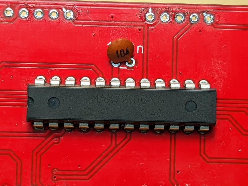 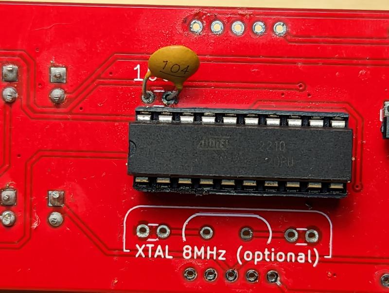 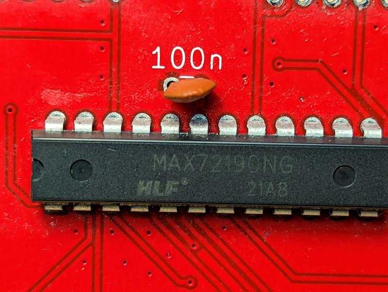 The iron was set to 300ºC The board does illuminate again. I'm using a PSU that looks like it came with a Chromecast at one point. It's rated (and outputs, measured with a multimeter) 5v DC at 1 Amp ------------- |
| [top] | |
| mit | Posted: 9 Mar 2023, 10:12 PM |
|
yeah whatever Admin Posts: 687 Joined: 4-May 16 |
That all looks fine, so I'm not sure where the problem is, but we'll find it. Good to hear it still turns on at least. I think the next step I would take would be to remove both transistors and work backwards until we find the problem. If you desolder both transistors and turn the clock on, it should display nothing at all. If the date side lights up at this point, then unsolder the 50K resistor too, and if it still lights up, then the short is somewhere between the 50K and the display chip. If removing the 50K (and the transistors) gets the display to turn off, then the short is somewhere in the Assuming it doesn't light up, you can then individually send a small current into each ISET pin with a resistor. If you take, say, a 20K resistor and put it across the two pins of the transistor footprint here: 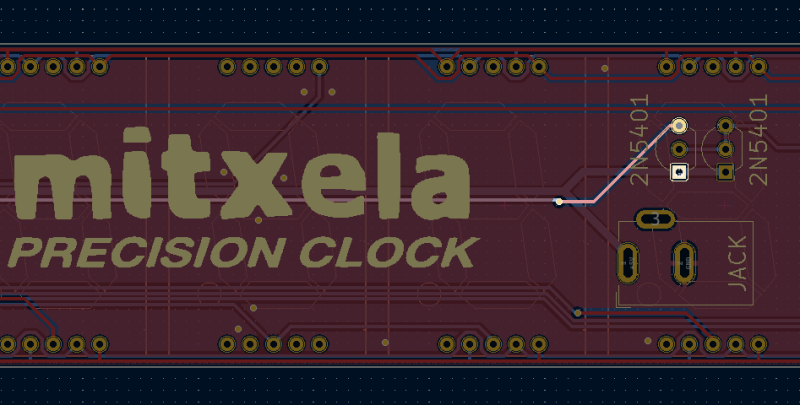 it should light up the time side. For the date side, it'll be easier to put the resistor across the pins directly on the chip here: 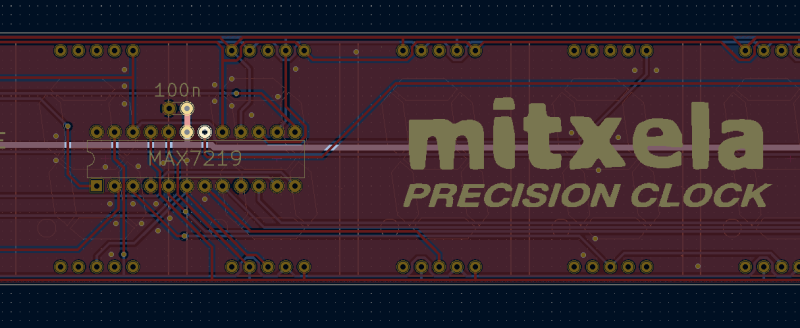 If that has the same effect on both chips, that will at least confirm they're working. I haven't actually tried doing this on an assembled clock, you might need to power-cycle the clock after each change (but probably not). Obviously power it off while soldering though! ------------- |
| [top] | |
| Paradox | Posted: 10 Mar 2023, 04:36 AM |
|
Member Posts: 16 Joined: 2-March 23 |
Removing both the transistors, and then the display chip, doesn't fully turn the clock off. The date side stays illuminated, and the time side is very dimly lit, but starts its count up process. I have most of the displays removed for debugging. The GPS module also illuminates, you can see the glow in the right side of the image 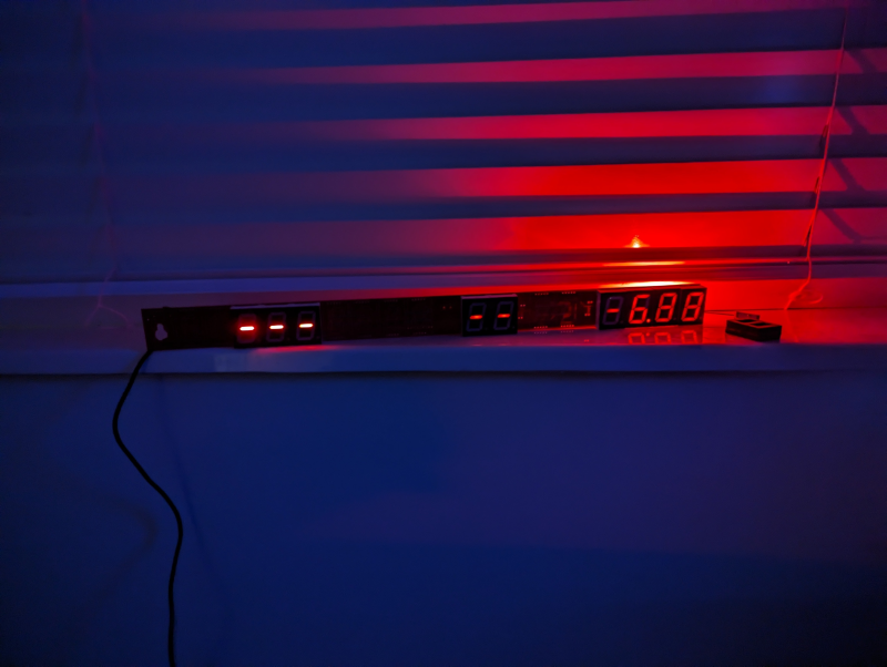 ------------- |
| [top] | |
Sign in to post a reply.