
Wobbler
19 Aug 2014Progress: Completed
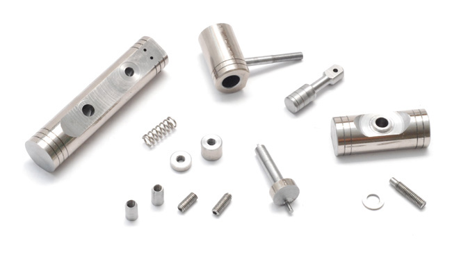
It's time to take it to the next level. I bought a lathe. At some point I shall post a projects page listing my tribulations with it and modifications to it. But for now, let's focus on that rite of passage for new lathe owners: building a tiny steam engine. My first wobbler!
It was made almost exclusively on the lathe using the four-jaw chuck. I refuse to buy new material when I have so many broken printer shafts available (I don't know quite what alloy it is — I had thought stainless steel but it's very easy to machine) so the whole thing was made out of a 13mm rod, which was the thickest I could find.
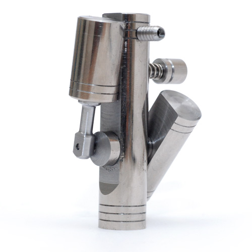
The diagonal bit is the flywheel, which needed to be larger than the rod diameter, so I took a rather unconventional approach. It isn't particularly well balanced but of course that can be adjusted to offset the weight of the piston.
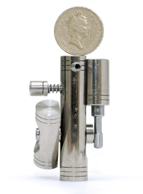
Takes a fair bit of puff but it will run on your breath in either direction. I think that's pretty impressive for a single-acting single cylinder. Here it is with a rather worn pound coin balanced on top for scale.
I didn't follow any plans when I made this but I think it's pretty difficult to make a wobbler that won't run. I had once tried to make one from scrap aluminium and some old nuts and bolts using a hacksaw and a file. The workmanship was awful, but with enough input pressure even that would run. I did try and be a little more precise with the measurements here.
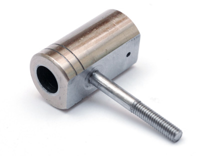
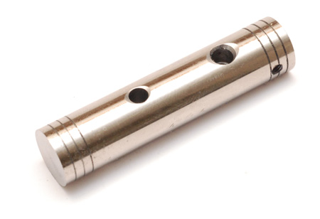
I started with the cylinder. I don't have a mill so the flat was made by creatively chucking the part in the four-jaw and facing off. Then, the pivot hole was drilled without unchucking it so as to ensure it would be perfectly perpendicular to the surface. The hole does not penetrate into the bore. The pin was turned down and tapped M3, then press fit into the hole. This is probably the weakest point in the design as the first time I ran it on compressed air the pin shook out and the thing fell apart. I later superglued it back in.
I don't have any reamers or tiny boring bars so even after very careful drilling the inside of the bore was quite rough. The first piston I made was a terrible fit. I then ran the ruined piston in the lathe at high speed while sliding in and out of the cylinder to try and lap the bore.
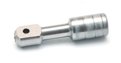
This worked remarkably well and the new piston had an excellent fit. Makes a nice healthy pop when pulled out with the valve closed. Those groves are supposed to hold oil, but it actually runs fine when dry. The conrod was turned down and then flats were cut with the same technique as before. In one of the few operations not on the lathe, for some reason I took it to my cheapo drill press to cross drill and missed by a long way. I should have lengthened the conrod section to make it less obvious but I didn't notice how far off it was until after I'd parted it off the stock. Given the damage the jaws seem to do to this metal it probably isn't worth trying to chuck it on my perfectly fitting piston.
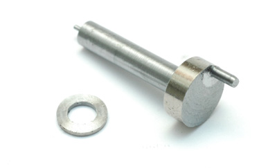
The crankshaft was turned from a single piece by offsetting it in the four-jaw. This, I must say, is a very satisfying thing to do. By a miscalculation the stroke length ended up being 7.5mm when I had intended about 6mm which is the approximate size of the bore. I have no idea how this affects anything really.
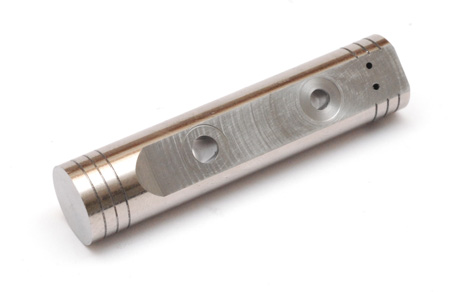
The standard, or column, that everything attaches to was given the same treatment for a flat face. You can see that the toolmarks all circle around the pivot hole which should help cut friction. Actually, despite the interrupted cut, the surface finish is very good indeed.
I know there are a number of ways of marking where to drill the valve ports but I chose to just turn down a little pin that fits snugly in the cylinder's valve with a point sticking out. Sharpie on the standard and assemble. Turning it over a few times scribes a nice arc that shows where to drill the ports. I took it to the drill press and - blast! - missed again, out by about 0.5mm on one of them. The ports are 1mm, perhaps I should widen them.
Doing this also revealed how far out of center the pivot hole is, even if it is perfectly perpendicular to the surface. I suppose I had no way of indicating that before I begun. Naturally the solution is to do this on a mill.
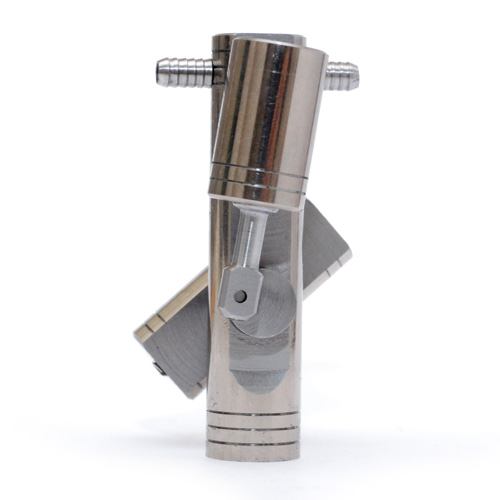
The pivot hole was drilled out for half the depth to accept the spring. Guess which household item it was salvaged from... There is no bearing as such, just a plain hole. It is no doubt in need of a reaming. Perhaps I should add an oiler hole. The steam ports were tapped M3 but without a bottoming tap I could only get about two full threads in there. I carefully bored through an M3 bolt to make the barbs, then remembered that the only pipe I had needed a 4mm barb.
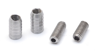
My M3 die turned out to be tapered both sides so I couldn't think of a tidy way of producing a shallow M3 thread then an immediate shoulder to 4mm. Instead I very carefully produced thin sleeves, internally threaded, which increase the diameter of the M3 barb.
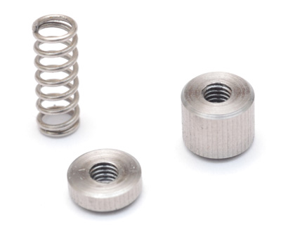
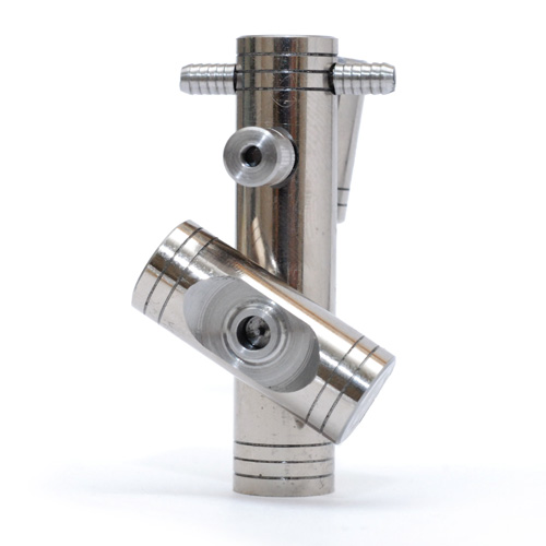
I had built a simple indexing device for the headstock and as a test had produced a graduated bar. This seemed like perfect material to produce a pseudo-knurled nut for the pivot pin. I soon realized that I would need two nuts, to lock in place, but had ruined much of the remaining knurl with a rather wide partoff tool. This meant the next nut had to be quite thin. It looks fine and is perfectly functional so I see no reason to remake it.
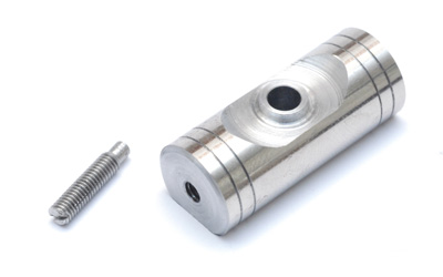
I had carefully indicated the hole through the flywheel to be centered, end-to-end of the 30mm bar, but only aligned it by eye for the other plane. This was almost unnoticeable until I machined the decorative recess which draws attention to how far off the center hole is. Additionally, the hole is slightly larger than the crankshaft, so when tightening the setscrew it further offsets the balance. However, with this imbalance the engine is still able to run despite not having a stand. The slot of the screw was just cut with a hacksaw.
So there we go. A real steam engine, even if I have yet to run it on steam. What's next? Perhaps a stand if I can find some larger material. Then, a boiler I think. A video will follow shortly, hopefully featuring genuine British steam.
And then, more engines!
Update
Here's a quick video - real steam will come later.