
Wireless Sustain Pedal
28 Mar 2015Progress: Completed
I suppose it makes sense that wireless sustain pedals don't seem to exist. Most keyboards are fairly stationary after all. But with all my keytaring I was starting to find my tangled cables to be pretty annoying.
My first idea was to butcher a cheap remote controlled car. The main disadvantage of this is the transmitter is always on, and would eat through batteries.
When I discovered just how cheap you can buy a 433MHz transmitter/receiver pair (seriously - 99p), I got one just to experiment with. You can't just transmit a DC signal, you would need to encode it somehow. You also need to decode it, as the receiver gives a ~2Hz square wave when it's idle.
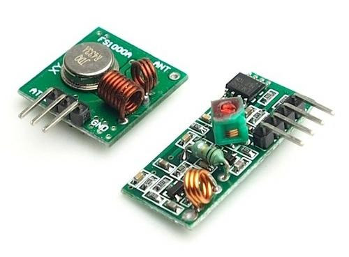
Luckily, simple encoding and decoding chips are easily available, and you can buy a transmitter/receiver pair designed as a 'remote switch', intended for garage doors and so on. These come with a relay, cost about £4 and sound perfect for what I wanted to do.
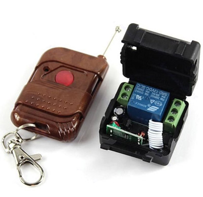
The first problem is that these run on 12V. The transmitter takes a 12V battery, although I'm sure you could power it from as little as 5V if you didn't mind a shorter range. You could run the receiver on the same type of battery but it probably wouldn't last very long. I'd be modifying the keyboard to have this internally, so I wanted to run it from 5V. The only reason it needs the high voltage is to run the relay, and you can get 5V coil relays, or even 3V coil relays.
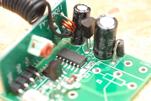
Here's a closeup of the receiver with the relay and terminal blocks removed. Power comes in on the right. I guess the diode just protects from connecting the wires the wrong way, then there's a smoothing capacitor. The three-legged package that looks like a transistor is actually a 5V regulator, followed by another smoothing cap. You could stick 5V into this and you might get 5V out, but we're losing at least half a volt through the diode and the regulator wouldn't be doing anything anyway, so we may as well remove them.
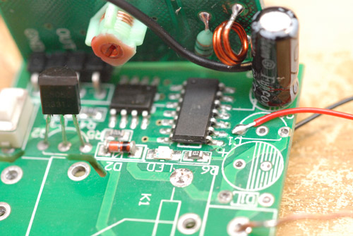
The other three-legged item really is a transistor, it's a PNP that opens one leg of the relay to ground. The orange lump next to it is the diode that protects the transistor from the voltage spike when the relay discharges. The eight-leg thing behind it is actually a 2kB EEPROM, as this turned out to be a programmable receiver. I would not be using this feature.
Incidentally, I recently invested in some 30AWG stranded wire, and it's the best thing I've ever bought. Life would have been so much easier if I'd gotten hold of this ten years ago.
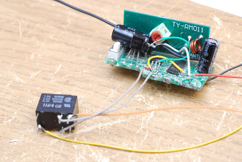
So there's my 5V relay. I wrapped this up and stuck it in the keyboard.
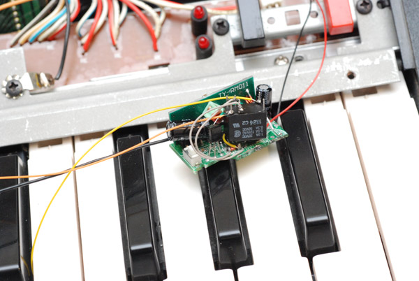
Did it work? Eh... sorta. The sustain switch on the keyboard is push-to-make. I'd wanted to use the relay to keep the wireless module completely isolated, but the problem was, the relay drew too much power. Even with extra capacitors it was causing issues with the receiver, and unless the transmitter was very close, the relay would flick on and off instead of staying on. More work was needed.
Well, it was time to start probing the keyboard further. Neither of the wires to the sustain switch were showing anything to my multimeter, but before I got out the oscilloscope it became clear that you can activate it just by pulling the signal line low. Perfect, we can throw out the relay and wire it straight to the transistor leg. This worked, and at last we could move the transmitter a significant distance away. Not that I'd be needing the distance but it's nice to have that knowledge.
Unfortunately, there's a substantial lag on the receiver that I'd hoped was due to the relay switching time, but it wasn't. The encoder/decoder pair have an eight-bit address which it has to pick up, but even so that doesn't explain the 200ms or so lag that I'm getting. The transmitter, as you hold down the button, sends its packets about 10 times a second. I assume the receiver waits until it's sure the transmitter has stopped before changing its state.
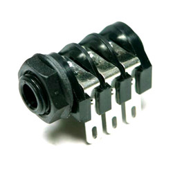
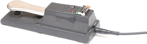
Well, the system is usable and I decided to finish the pedal anyway: this meant removing the cable wiring up the transmitter. I fitted a switched socket where the cable used to be, so that plugging in an ordinary quarter-inch jack automatically disconnects the transmitter and turns it back into a wired pedal.
That was the plan, anyway, but for an item as large as this with so little circuitry inside, there was remarkably little room inside the enclosure. It took substantial modification just to fit the socket inside, and after several different ideas that didn't work, eventually I threw in the towel and mounted the transmitter circuit on the outside. Although the pedal was only a couple of years old, when I opened it I found the plastic had cracked around the mechanism, so it's probably a good idea not to weaken the structure any further.
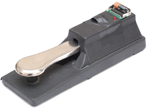
Having the LED visible is nice, and at least it's very easy to change the battery. If there had been room to fit it all inside, I would have swapped the battery for a 9V one which would last longer and probably be cheaper than the somewhat esoteric 12V thing.
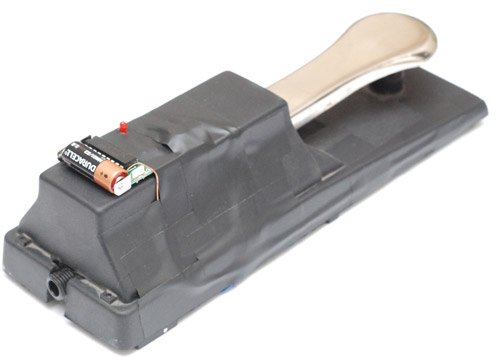
That much electrical tape sure is ugly. Under it is the antenna, which I forgot to mention. This transmitter/receiver is actually 315MHz, so a piece of wire 23.8cm should do it. Having it bent in an L shape probably reduces the effectiveness somewhat, but we really don't need much range to this anyway.
Now that the wireless pedal was actually a pedal, I could judge how bad the lag really is, and the answer is, pretty bad. It's fine for simple piano playing, but even then the lag is noticeable. Further work is needed.
I think for a successful wireless sustain pedal, we would have to have an always-on transmitter. Lag would be completely eliminated in that case. With a rechargeable battery I'm sure it wouldn't be too bad. Part of me wants to build my own encoding system though, that just transmits a 'pedal on' and 'pedal off' signal when needed. If we dispense with the addressing there's no reason the lag couldn't be cut to under a millisecond.
One unexpected benefit of this mod is that using it in wired form, but with the cable disconnectable, solves much of my wire-tangling woes. Perhaps that would have been enough of a modification.
Update
(a few weeks later)
The lag... the lag! I couldn't deal with it, and that made the wireless part of this invention useless. In typical fashion, I came back to this project with a vengeance and a sledgehammer solution.
A microcontroller and one of those 433Mhz units. The goal would be to only use power when changing state, just a 'pedal on' signal and then a 'pedal off' when needed, sleeping in between. To ensure absolutely zero current when the pedal is up, the switch directly cuts power to the circuit.
The circuit I built was something like this:
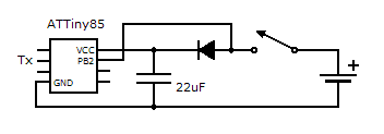
where Tx goes to the transmitter (along with power and ground). There was also a 78L05 regulator in there for using it with 9V / 12V batteries, something I didn't measure was if there was any delay to powering up the regulator.
The idea is that the switch closes, powers up the capacitor and the ATTiny85. It immediately sends the pedal-on signal and then waits, listening to pin PB2 for the voltage to drop, and when it does, sends the pedal-off signal powered by the capacitor. With the capacitor powering the transmit module as well, 22uF was easily enough to send the pedal-off command five times over. Another thing I need to investigate: how much power does the transmit module use when powered but not transmitting? It's certainly very low, but I powered it from the same capacitor just to be one the same side. It may have been acceptable to connect it straight to the battery, and then it could transmit at the full voltage.
I had a fair bit of difficulty getting reliable signals. The transmitter/receiver pair are quite sensitive to noise, especially for low-bitrate data. I think this is due to some auto-gain system on the receiver. An example, although it's quite hard to capture on camera, look at this scope trace:
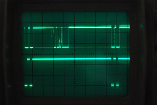
The lower trace is what I'm transmitting, and the upper is what's received, with the receiver about one foot away. It's very flickery in realtime. Even though the transmit line is high between those pulses (which means it's transmitting the whole time) there is still noise on the line. When modulated quickly, it picks up the signal well.
So, my pedal on/off signal ended up being a series of high/low oscillations just below the fastest bitrate possible, with the final state being high or low to represent pedal position. Picking this up without error wasn't easy either, since when the transmitter is off completely there's all sorts of noise that comes through. You can't just sample at a few times the bitrate, since the noise quite easily fits the criteria sooner or later. The best bet was to wait for the line to go low, then enter a loop checking the line stays low for the next n microseconds, then wait for it to go high and enter another loop and so on. This means we're sampling at effectively a few hundred times the bitrate, and the waiting for state changes realigns the framing. Even with this, it needed five or six oscillations to accurately differentiate the data from noise.
Total lag on this system - less than 1ms. Great!
(a few days later...)
This system worked. But... every now and again, due to some cosmic ray or disturbance in the aether, a signal would be missed. It may only be a one-in-a-thousand occurrence, but it was enough to ruin the whole experience. How infuriating - the only sure fire solution was to retransmit the pedal-on signal every few ms, and kill the pedal on the receiver if it times out.
After a few days of this, I decided I had to go back to the drawing board.
Hmmm.....
We want: no lag, complete reliability, minimal power usage and only need a range of a couple of metres. Fuck it, let's continuously transmit a modulated signal and kill when the signal stops. Lag should be in the microseconds if we work close to the limit of the bitrate.
(a few days later...)
I swear that the new system worked flawlessly when it sat on my desk. I used two ATtiny13s and I could reliably trigger it across the room when the transmitter was powered from a CR2032 coin cell. But again, when I built it into the keyboard it was occasionally missing the start of the signal. Oh boy. What could possibly be the problem? Such a simple system was foolproof, surely?
Well... the keyboard's case is partly metal, which might be attenuating it. But the antenna was in the plastic part at the base. Later, I was sniffing around on the circuit board and suddenly it all made a whole lot more sense: a 7905 regulator. That's a negative voltage regulator. I had, of course, connected the Vcc of my circuit to the positive of the incoming power, and the ground to the ground of the keyboard. I supply the keyboard with 5V instead of the 9V it expects. But with a negative regulator, that means the 'ground' of the circuit is actually the regulated voltage, so the circuit was only receiving about 3.5V because of the dropout voltage of the linear regulator.
Could this have been the problem? To be honest I'm not sure, and I didn't fully investigate since at this point I was getting annoyed that my speakers were somehow picking up the 433MHz signal. I suppose the modulation frequency was in the audible range.
At this point I got distracted with a different project, and I do feel a little disappointed having sunk tens of hours into a wireless foot pedal with no real satisfaction. I'm sure I may some day come up with a perfect implementation of a wireless foot pedal (2.4GHz, perhaps?) but for the meantime I decided to throw my efforts into a different modification: adding tons of assignable knobs.