
Toolmaker's Clamp
20 Jun 2019Progress: Complete
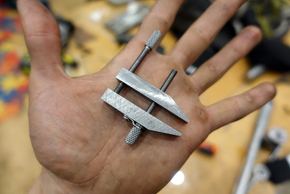
At last I have access to a milling machine! And a traditional first project on a mill is a toolmaker's clamp.
The Bridgeport in question is at the London Hackspace which has recently moved to west London. For me at least that makes it a lot more convenient to get to. They need more members, so if you're reading this and you live vaguely nearby, make sure to sign up.
(Apologies if the pictures are not up to my usual standard, I didn't have my proper camera with me.)
Tram
My first cuts were very uneven, the shell mill was only cutting on one side because the head was out of tram. A digital angle gauge on the quill showed it was off by about 0.3 degrees compared to the bed. We could just straighten it up with the angle gauge but I thought I'd have a go at doing it properly.First we remove the vice by undoing the bolts and sliding out the T-nuts. The vice weighs about 30kg so we really don't want to drop it on our toes.
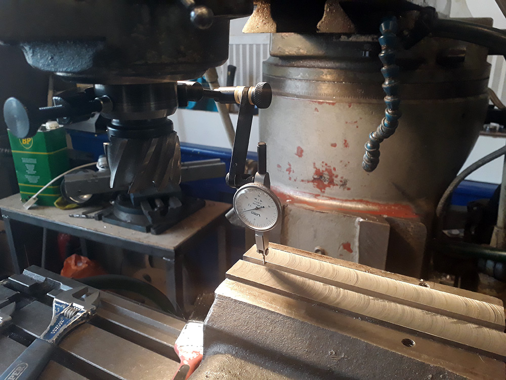
Next we wipe down the bed and mount a dial indicator onto the spindle. One way of doing this would be to stick a magbase onto a drill chuck, but in this case I was able to borrow an indicator mount with a clamp designed for this.
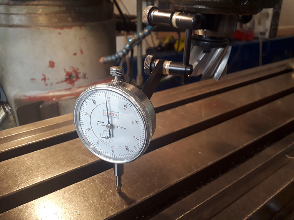
By carefully swivelling the indicator around we can accurately measure the angle between the head and the bed. There is a lot of wear in the bed, so it's important to make lots of measurements, moving around the bed to average things out.
To tram the mill left/right (which is where the problem was) we loosen the four bolts on the front, and then turn the bolt at the back right. As we approach the correct position, we snug the bolts down and move the last fraction by gently tapping the top of the head with our hand. We then tighten it properly and check it hasn't moved. In this case I was able to tram the head to within three divisions on the indicator (0.03mm, about 1 thou) which is plenty good enough, and certainly a lot better than it was.
I also measured the front/back (nod) and found it was within 4 divisions, which is good enough for me not to be bothered about it.
The last step is to mount the vice again, and make sure it is aligned with the Y axis. We do this by lightly tightening the bolts, tightening the jaws, setting the indicator on the fixed jaw and running the bed back and forth to see the alignment. Then tap it true with a soft hammer and tighten it down fully.
Squaring stock
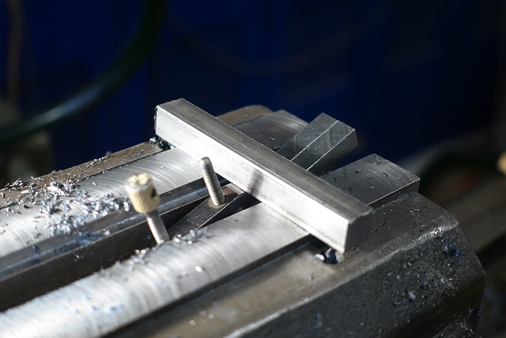
I started with a 12mm mild steel bar which was square enough to be held directly in the vice. The jaws have a lip which is easier to use than fiddling with very thin parallels. I took a few cuts and was happy to find that the shell mill was performing much better now.
With a reference surface established we rotate the part 90 degrees and clamp again, trying it both ways until the machined surface sits flat against the fixed jaw. Then we take another cut, and work our way around until all four sides are machined.
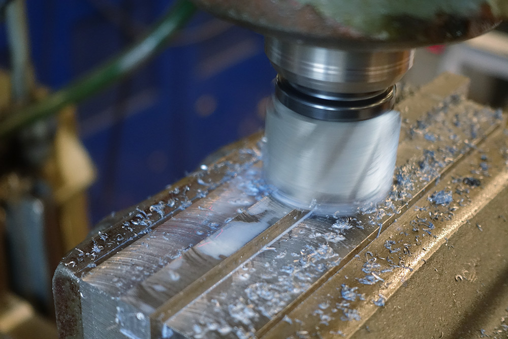
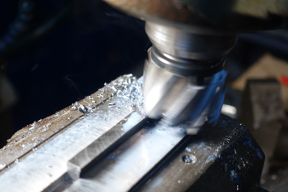
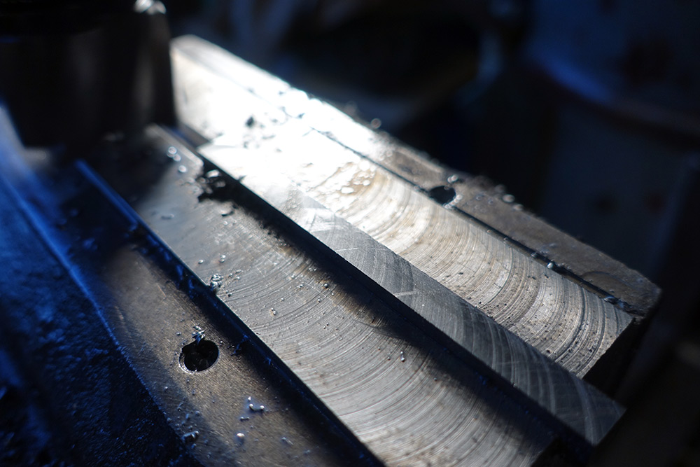
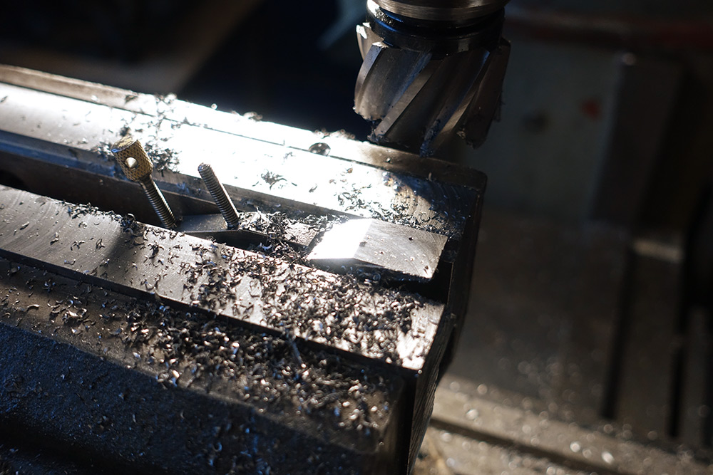
The dimension we're aiming for is 8mm so I tried taking a heavier cut and playing around with the feeds and speeds. Here is a nice shot of some coolant evaporating:
The finish is OK, very good in places but ruined by the occasional scratch marks. I think this is due to wear or slop in the ways. Dismantling the bed and re-scraping the ways is an extremely labour-intensive project we can save for another day.
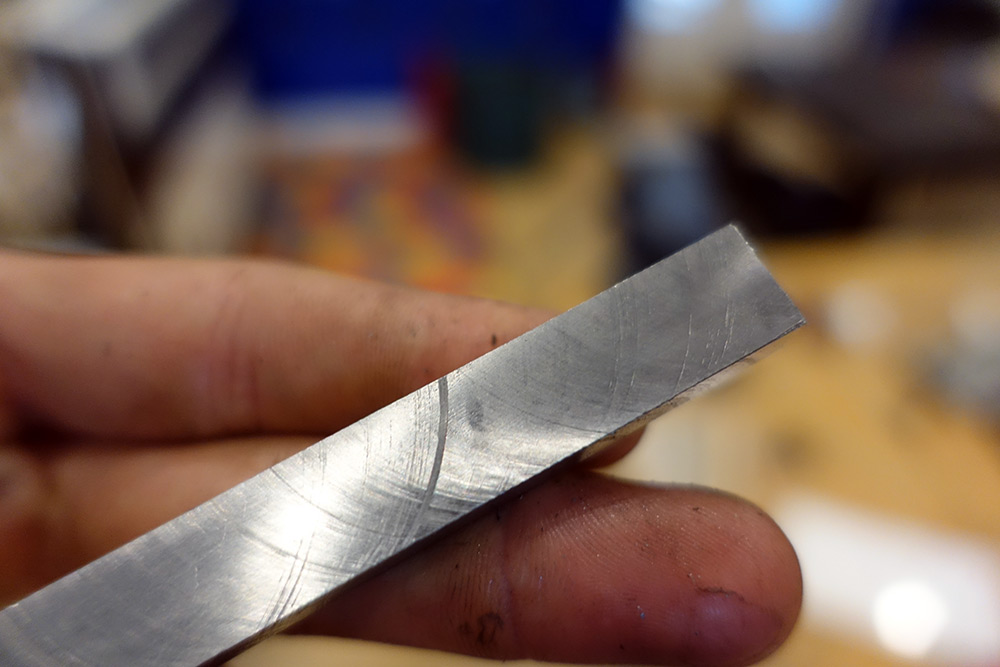
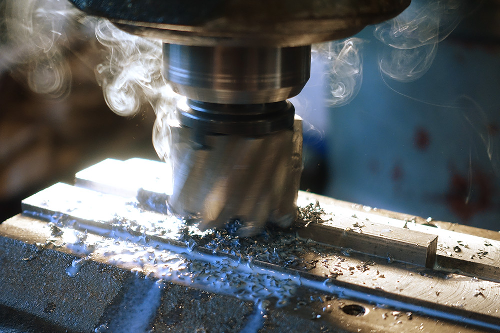
We've still got a fair bit of material to remove so I tried a few more permutations. This time doing a climb cut:
This isn't really the right tool for getting a nice finish, but even so the results are somewhat underwhelming.
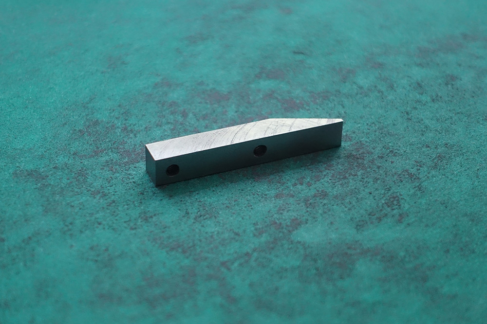
Nose Angle
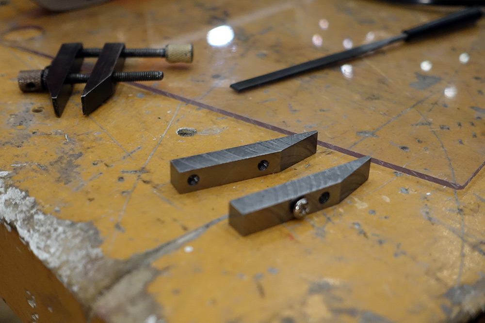
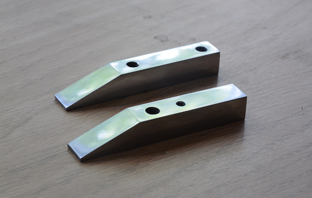
With the part to size we cut it in half with a hacksaw, and take off the burs with a file.
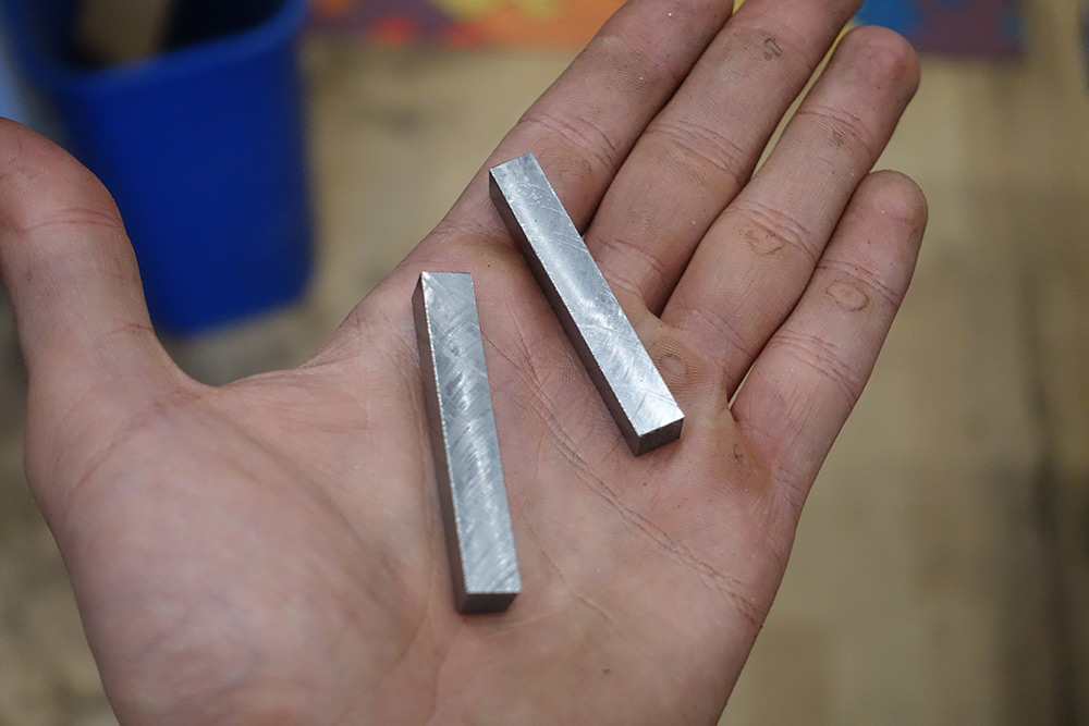
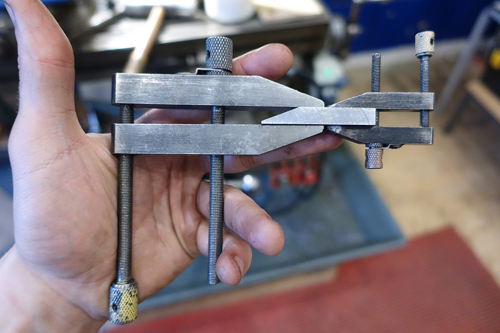
Next I used our reference clamp to hold the two pieces together. By placing the saw marks together we know the dimensions of the two halves match exactly. My calliper measurement of 8mm was not particularly precise, so there is also a rotation to worry about. In this case the toolmarks are very useful for finding the orientation where the clamp holds both pieces evenly.
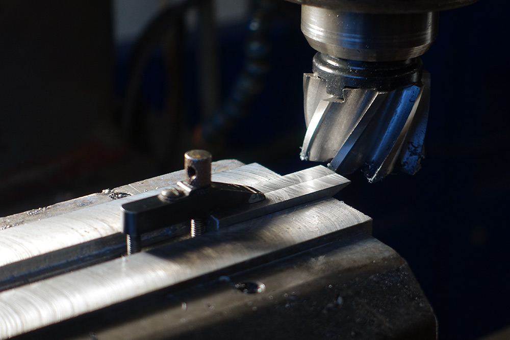
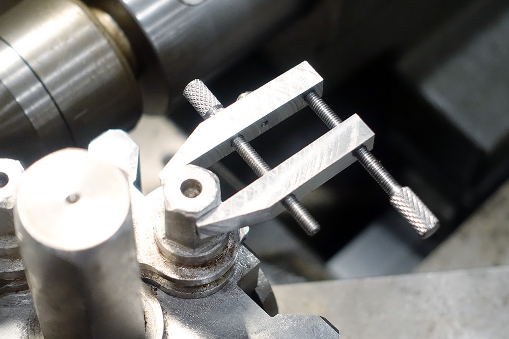
I used the nose angle of the existing clamp as a reference. The remaining bit of steel stock, with the machined side facing down, is used to square up the clamp's angle with the vice jaws.
It's not exactly precision work since the angle is basically cosmetic, but the technique seemed to work well.
I deliberately took this a little lower than we need, so that I could flip the parts and tidy up the blunt nose.
Lastly we want to tidy up the saw marks, which means transferring the parts to another clamp, without losing the alignment. Luckily there is no shortage of clamps around here.
The reference clamp actually has rounded ends, but I think I'll keep the nicely squared ends on my version.
Holes
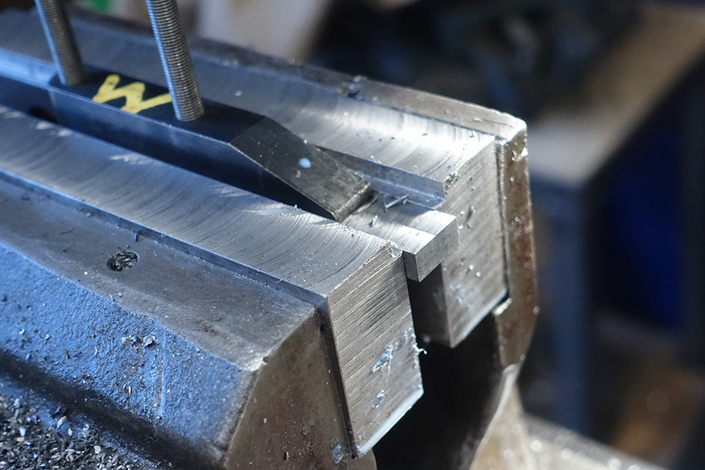
I placed the first part in the vice and aligned the end of it to the end of the jaw. This will be our reference for when we swap the other part in.The first hole was simply aligned by eye. It doesn't really matter if it's slightly off centre, so if it looks centred, that's good enough for me. From there I zeroed the DRO, so that the second hole is a known distance away.
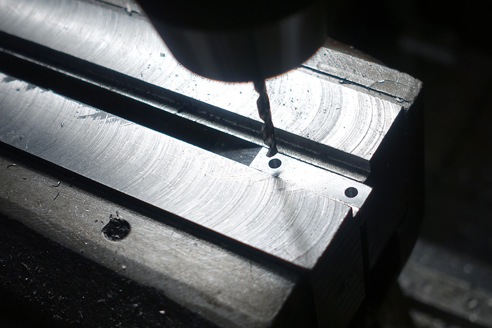
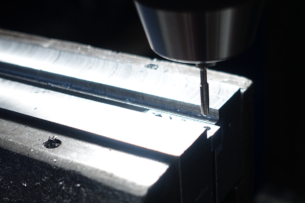
The proper tap drill for M4 is 3.3mm. I have a few drills of that size at home but I forgot to bring them with me. 3.5mm is close enough, and it's probably a good thing to make the threads a little looser in a clamp like this. I felt confident enough to tap the holes under power, at very slow speed of course.
The other part needs a clearance hole, a blind hole, and a further tapped hole to hold a bolt that keeps a little retaining piece in place. The reference clamp has a blind tapped hole for this bolt, I only had taper taps with me so I made it a through hole and tapped it M3.
Lathe work
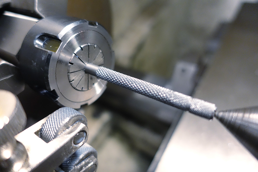
It would have been nice to start with something wider, but I only had a 6mm steel rod to make these parts. In order to hold this small diameter I used a six-sided collet holder, held in the three jaw chuck. This is easily good enough for what we're doing, repeatability is of no concern here.
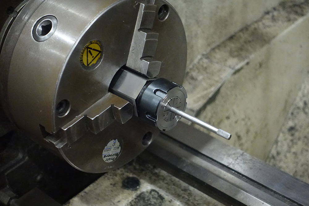
You can see a test knurl I'd done on the end there – that was not done with that much sticking out. The first step is to face and spot drill the rod for a live centre.
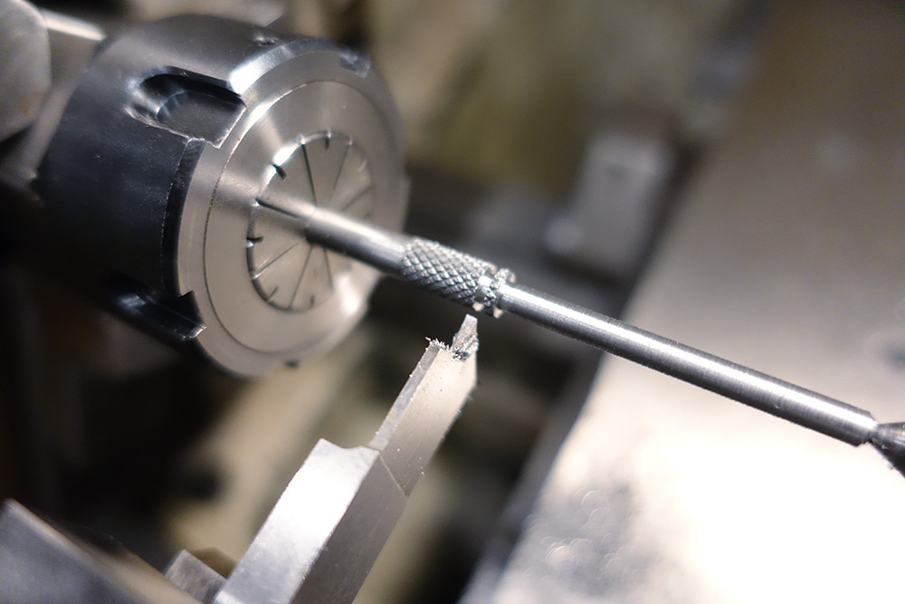
Using a clamp-type knurling tool is effective but I found it quite hard to get the knurl to track correctly. The problem is that the diameter is not matched to the tooth-spacing of the knurling wheels, but I don't want to take any more material off as these handles will already be a bit on the small side.
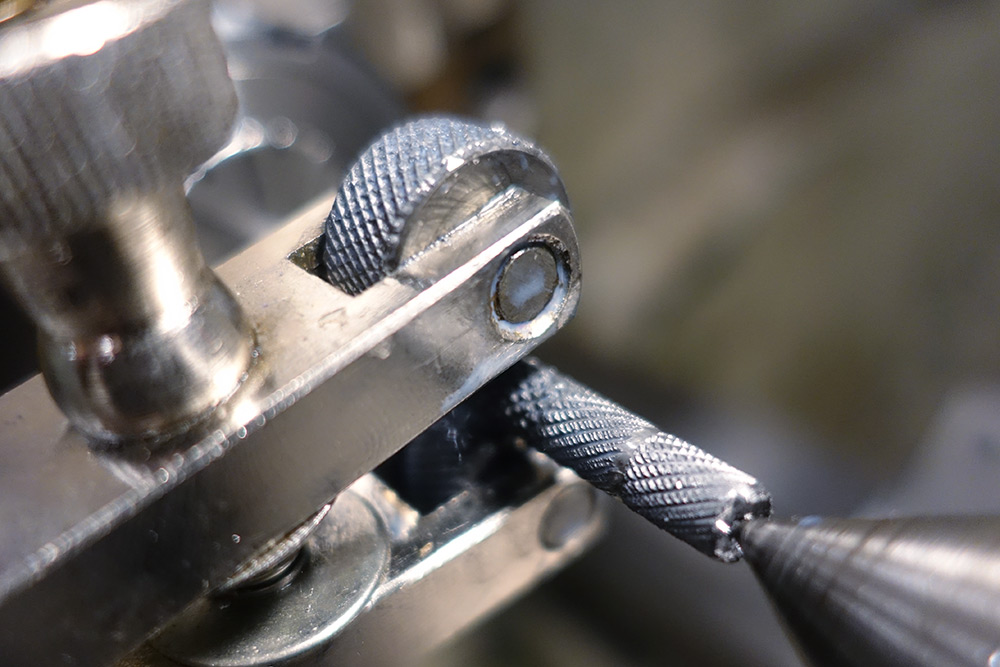
My solution is to have several attempts at it on the waste part of the rod, and once the knurl is tracking correctly we can walk it over to the other end.
Beautiful. The rest gets turned down to 4mm ready for the M4 die.
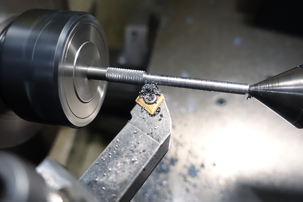
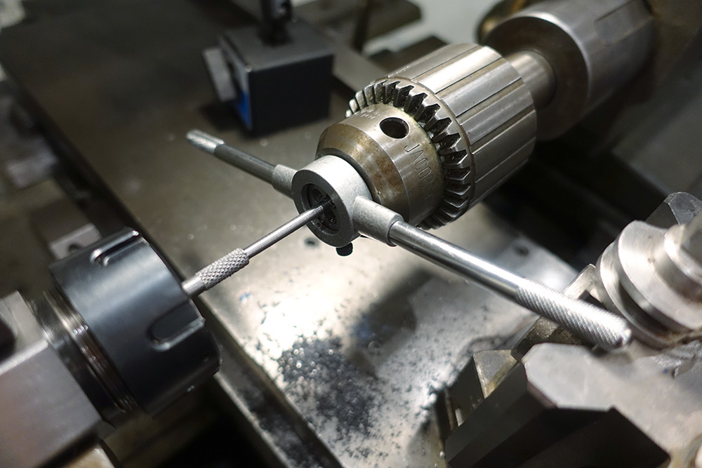
There may be a tailstock die holder somewhere but for this I just used the drill chuck to keep it perpendicular while I turn the part by hand.
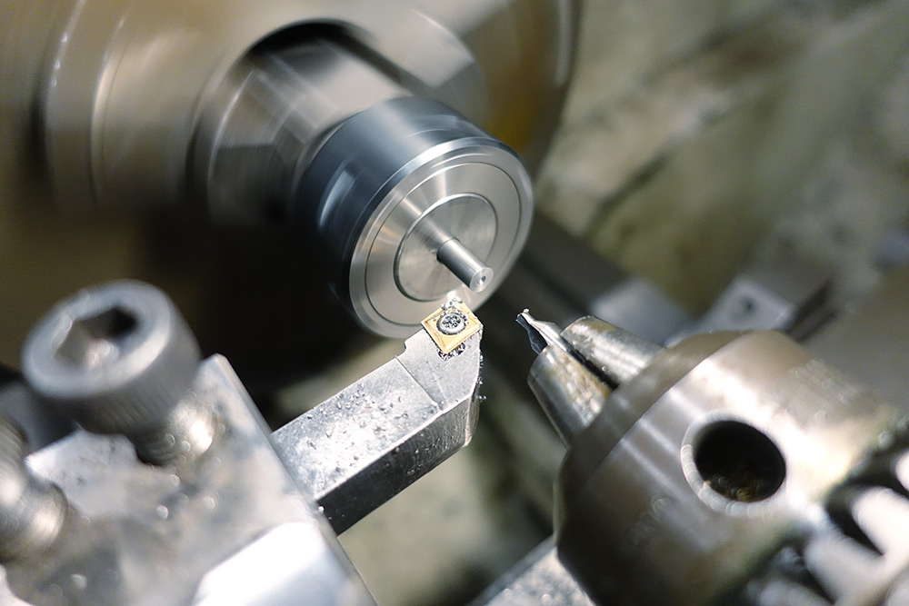
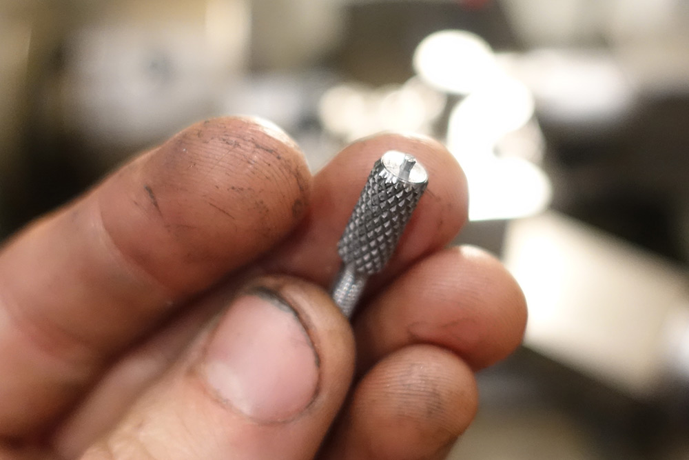
I then switched back to the live centre for parting off. I parted off part of the way, then added a chamfer, then parted off the rest of the way. It leaves a little nub which can be removed with a file.
The other part is pretty much the same thing except we add a little groove for the retaining clip. This was the narrowest parting tool I could find.
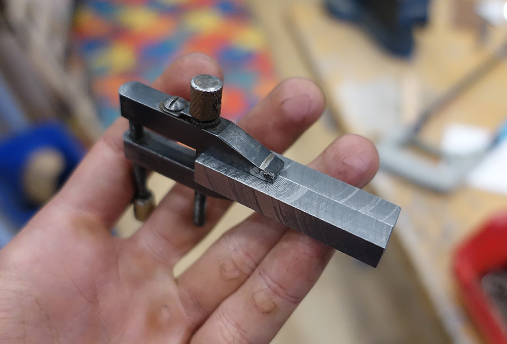
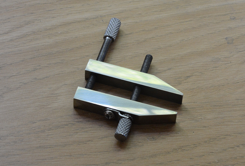
And with that, we are now able to clamp things!
Sheet Metal
This last little component is quite fiddly and tedious to make. Starting from a rather rusty bit of 1mm sheet, I used the sharp square edge of the remaining bit of square bar stock as a guide to try and form a joggle.
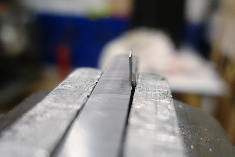
This kind of thing takes a lot of practice to get right.
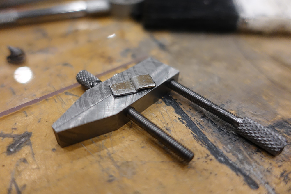
Drilling holes in tiny pieces of sheet metal is a nightmare. The best thing to do is to hold it with mole grips or strong pliers so it's a little less likely to snag. My holes did not come out particularly clean, but given the shape we're working towards some filework is needed regardless.
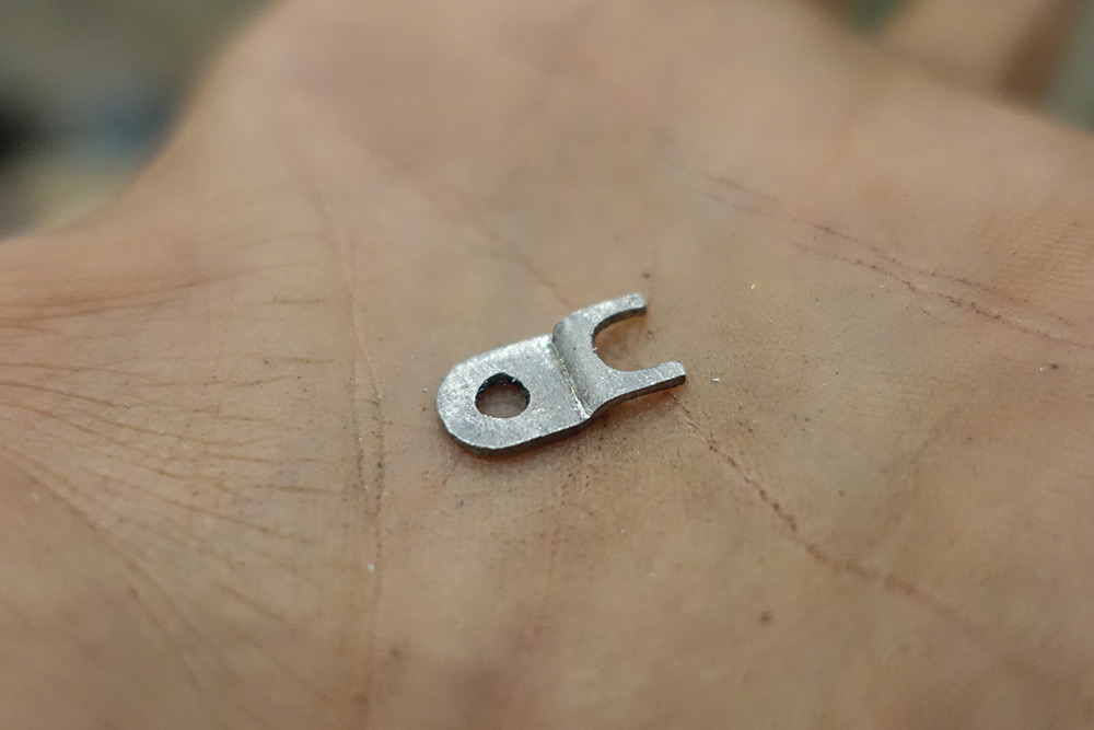
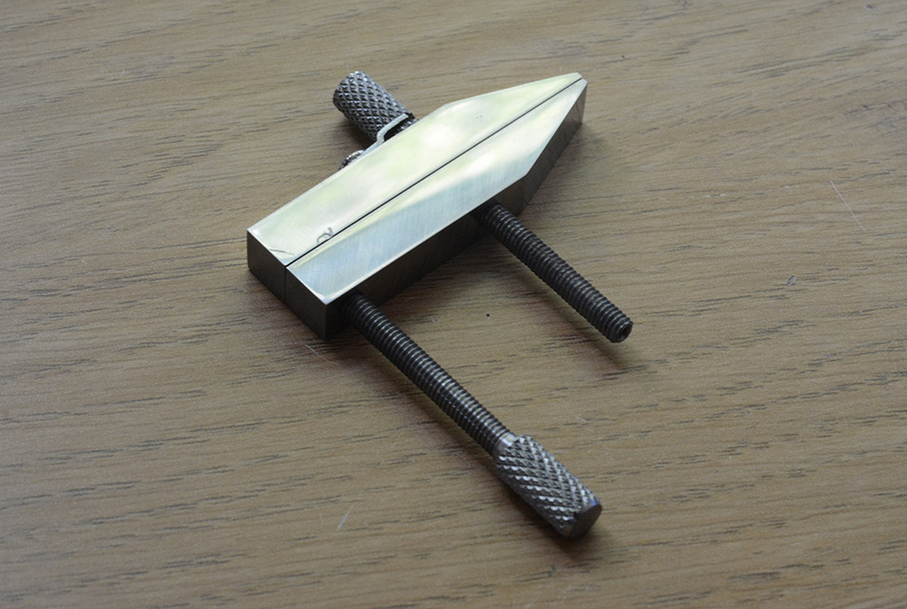
We have a working clamp! Truly, a thing of beauty.
Cleanup
The real joy of building a clamp like this, is that we get to spend the next few hours tediously lapping the surfaces to remove the toolmarks.
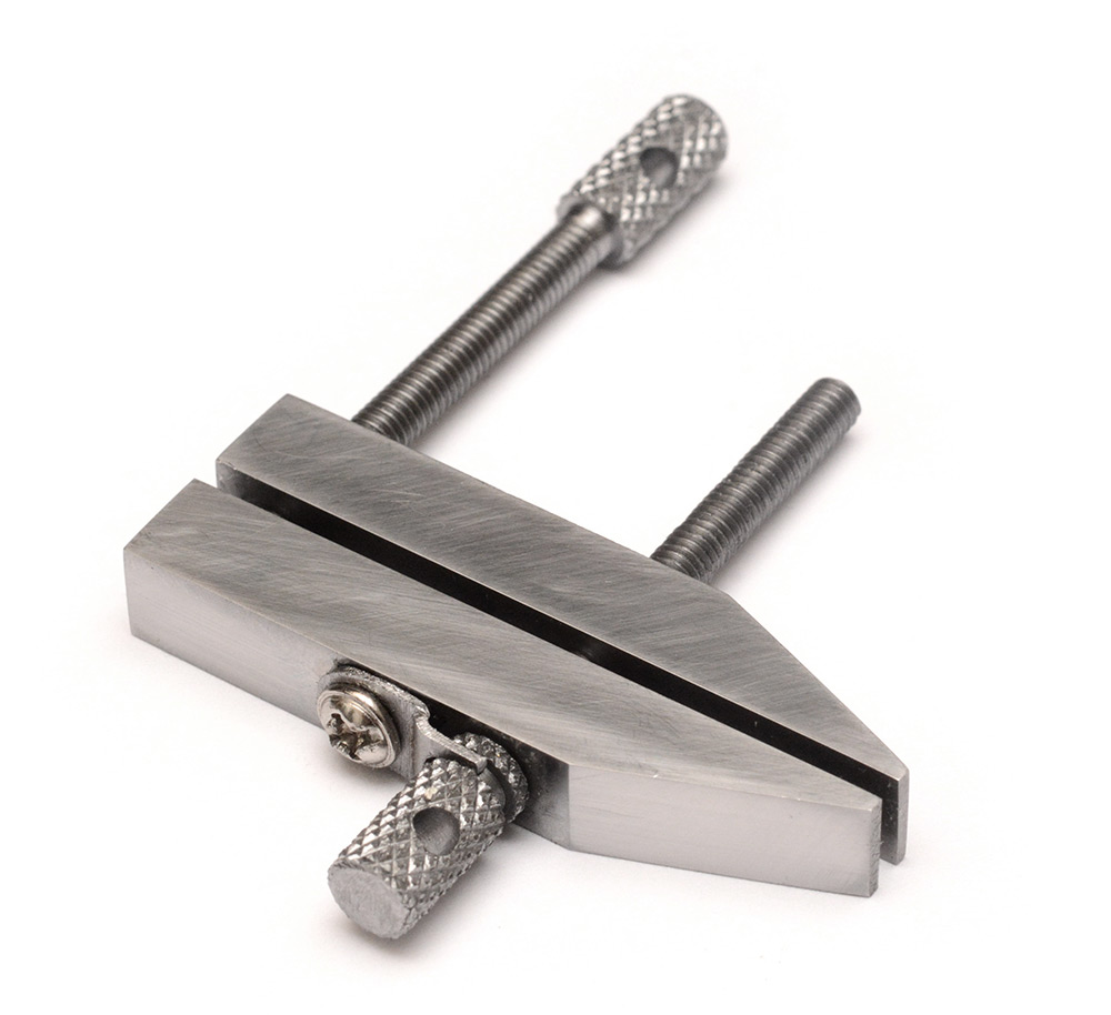
Starting with 120 grit, we work our way through the grades, with finer and finer grit, all the way to 2000...
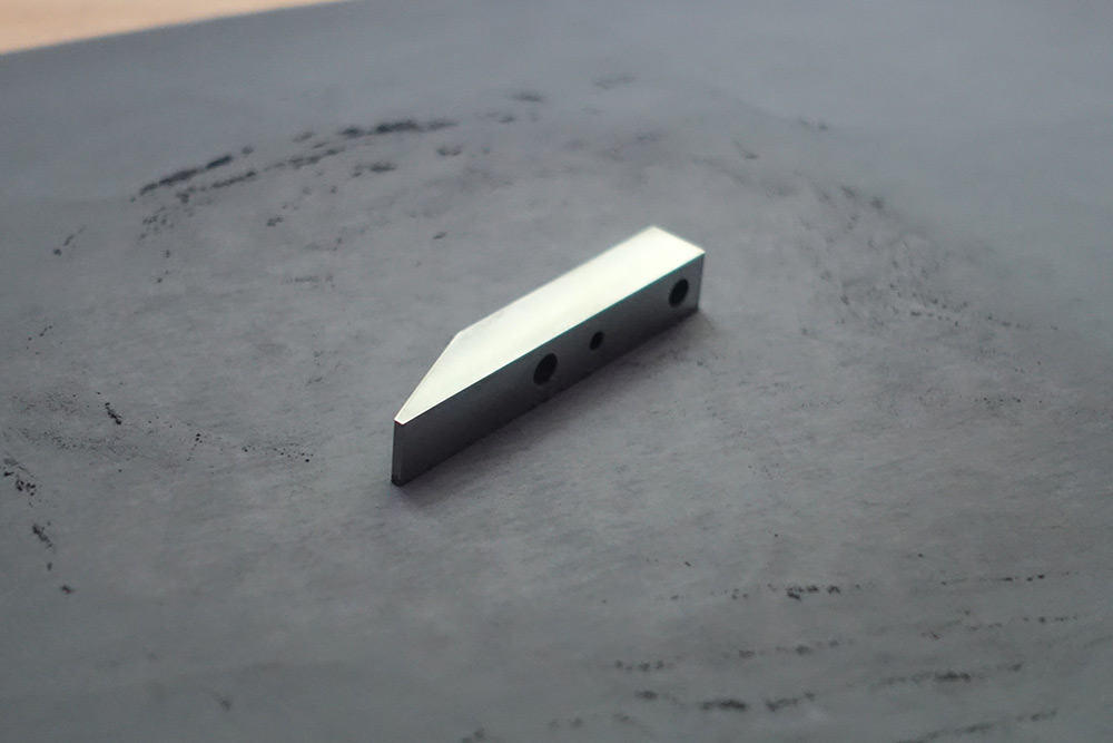
Of course I only stopped at this point because I didn't have any finer polish. 2000 grit is almost but not quite a mirror finish.
The benefit of such a surface finish is that it's almost impossible to use the tool without covering it in fingerprints.
Another benefit is that it's very good at drawing attention to the corner that got damaged in the vice, which previously was well camouflaged.
Final touches
I realized after polishing it that I'd forgotten to drill cross holes in the handles. I didn't take pictures of this bit, but I put it back in the vice wrapped in thin cardboard so as not to mar the surface. It's difficult to drill into a knurled surface, sort of the opposite of having a centre-punch to line it up. I ended up filing a flat spot so it was less likely to wander.
More ideas of things to do / ways to ruin it:
- Blue it by heat treating it / oil quenching it. Might make it more resistant to corrosion.
- Cold blue it
- Punch a name or maker's mark into it
- Etch a logo or some text. It would probably work well if I spray painted it, laser-etched some of that away and then covered it in acid.