
Mini Pitchbend Joystick
11 Sep 2017Progress: Completed
- Motivation
- Construction I
- Construction II
- Construction III
- Constructions IV through LIV
- Back to the Software
- The final product
- Video
- The calibration tool, and how to use it
- Source Code
Here's a project that started when a harmonica player named Brendan Power asked me to build a custom pitch bend device.
Motivation
There exists a MIDI harmonica called the DM48:
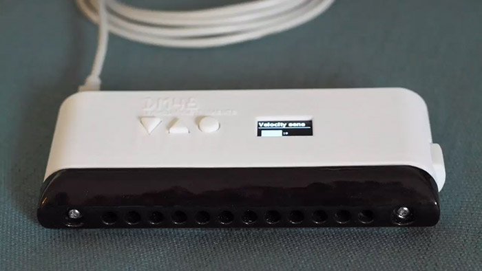
It apparently performs well, except for the lack of an ability to bend notes. Each hole is just a pressure sensor and flow restriction - there are no reeds - so bending in the usual way is impossible. I believe it has a mode which bends notes by just blowing harder, but this isn't the same.
The idea was to build some kind of retrofit USB device to add some bending power.
The biggest question is what sort of input method would be best. Real harmonica playing makes use of the resonance of your mouth and throat, which is very difficult to measure digitally. We spent a while talking about different possibilities for this. I thought that perhaps you could use an ultrasonic sensor to measure the internal volume of a player's mouth. I also considered some kind of capacitive sensor. But most of these experiments turned out to be dead ends in terms of a practical instrument we could build and play with. For real playing, nothing beats physical controls, like buttons, levers or pressure pads.
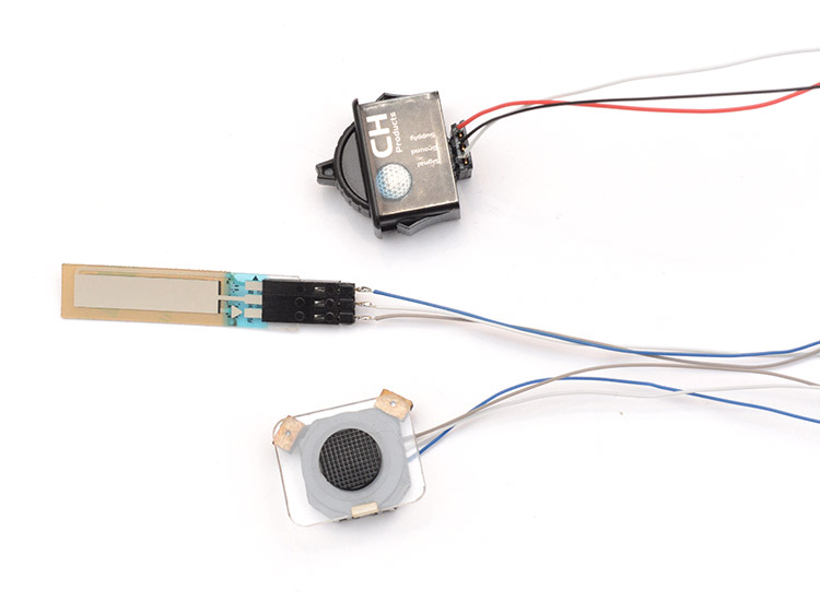
But what physical control to go with? Brendan contacted me after seeing the video I did on ribbon controllers. After some searching, we were also able to find several miniature controls which might function well. Further research and experimentation narrowed it down to the following three candidates:
• Ribbon sensor
An off-the-shelf 25mm resistive strip made by Spectra Symbol. The bend should activate when your finger touches it, and then spring back to in-tune when pressure is released.
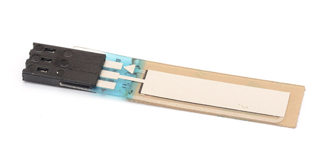
By arranging resistors in line with the ribbon, it's possible to have this 'spring back' position at one end, the other, or in the middle. The bending range is just a software thing.
• Thumbwheel
This controller made by a company called APEM has the advantage of looking like a miniature version of the bend wheels you get on MIDI keyboards. Its mechanism uses a hall effect sensor to detect the angle of the wheel, and outputs a linear voltage representing it. An almost infinite working lifetime is possible as a result, and almost no force is needed to move the wheel, except for overcoming the return spring.
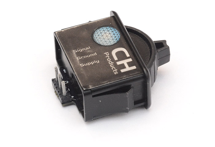
It's a wonderfully engineered device, with the main disadvantage being how expensive it is. Brendan managed to score a couple of free samples for experimenting with, but most distributors stock these thumbwheels at about £70 each.
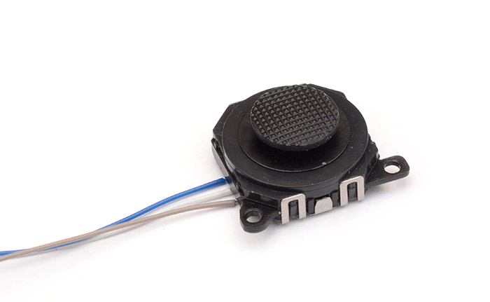
• PSP Joystick
The joystick from the original PSP console is available very cheaply as a spare part. This is a weird controller, which unlike traditional joysticks, is totally flat, and slides sideways under your thumb. My idea here was to build a plastic case around it to limit its motion to one dimension, to behave as a flattened pitch bend wheel.
There were a few other ideas we played with, buttons and pressure pads seemed promising, but it's hard to tell how good it is until you've actually wired it up as a working pitch bender. And so, assembly began.
Construction I
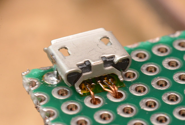
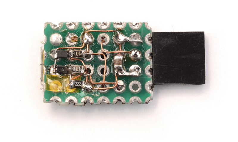
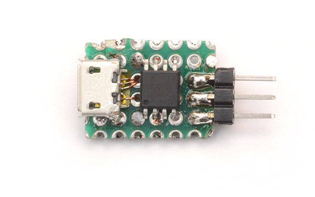
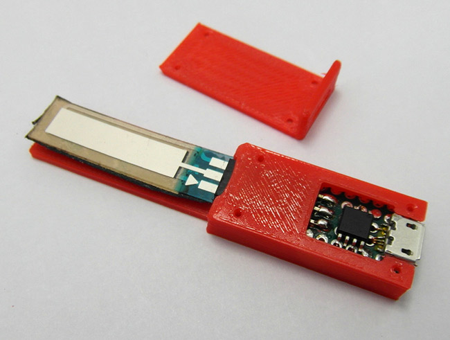
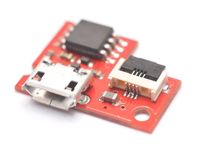
The first miniature pitch bend device was built to test some of these ideas out. Each of the input devices has some kind of connector on it, so I decided to build a tiny circuit which could detect which controller had been plugged in, and operate as a midi pitch bender accordingly. The whole thing needs to be tiny, because it has to mount unobtrusively onto a MIDI harmonica. Luckily, microelectronic prototyping is my area of interest.I started by soldering up a micro usb port. Four wires are needed, the fifth is left floating when you're not using USB-on-the-go.
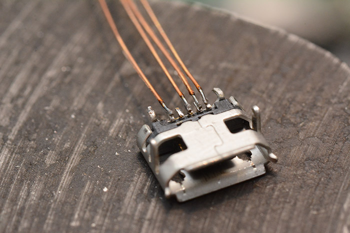
Then we securely attach this to a piece of protoboard. Some kapton tape is used to stop the wires shorting. I would very much like some protoboard of a finer pitch, 0.1" is just so 1980s. (Metric protoboard probably exists, but I bet it's a billion times more expensive.)
The ATtiny is the fiddly part. We want to be able to reprogram this easily, which means fitting a SOIC-8 test clip over it. In order for the clip to fit, we have to avoid spilling any solder on the top or side of the legs. This means carefully soldering wires underneath before attaching it to the protoboard.
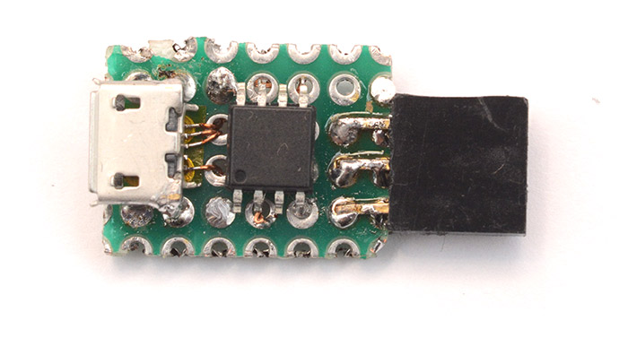
The large black thing on the right is a 0.1" header connector.
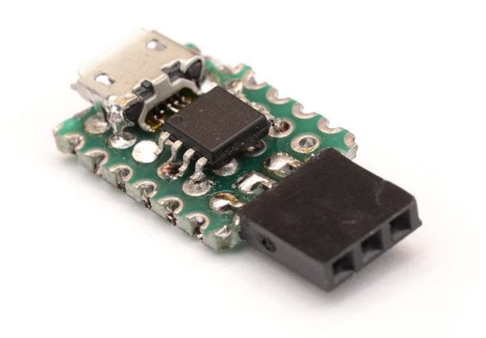
And the underneath is the usual mess of necessary components.
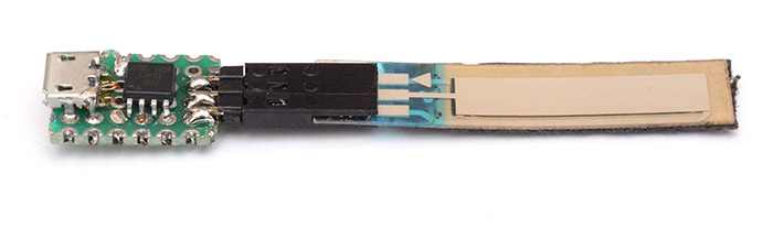
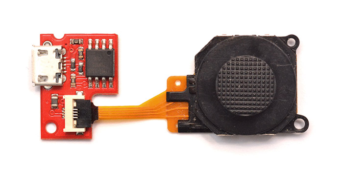
The three controllers each have a length of wire attached with a 3-pin header connector. For the PSP joystick, there are test pads underneath to solder to. I made the wires about 15cm so that the unit could be placed on the side or underneath the harmonica, while the control stays on top. I thought about having the wires much longer, and just having the circuit with a male USB plug, like I've done in the past, but I think having long wires with analog signals is probably asking for trouble.
This is the joystick upside down:
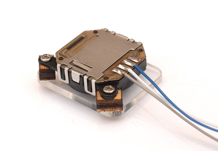
Obviously there are four pads but we only care about one dimension. I made a plastic guide to constrain it to a straight line by laser cutting a bit of acrylic. To attach it to the rather awkwardly positioned screw-holes, I laser cut little wooden squares with holes in, screwed them securely to the joystick, then superglued the acrylic onto the wood. This is a very quick way of attaching it without being permanent.
For the thumbwheel, it already had a header connector, but it wouldn't be usable (from a mechanical point of view) if it plugged straight in, so I made a male to female extension wire of about the same length.
Unlike the ribbon and joystick, the thumbwheel is an active device, and won't function if power and ground are reversed. The header pins are symmetrical, so to label the connector, I figured the easiest thing to do was just glue cut-off bits of wire of the same colour onto it.
The ribbon sensor's wire was not so critical, but I had to add a couple of resistors inline so as to give it a 'spring-back' position. I think they were about 100K. Since the pot is about 10K in total it shouldn't have any effect on the linearity.
The software uses emulated floating-point operations to scale the ADC input to the right range. Since it's just one multiplication per reading, this is easily within the processing power available on the 8-bit chip. It boots up with a 'min' and 'max' value, and by wiggling the controller the range expands to the correct numbers. This isn't something you'd want in a final product but for testing purposes it's a simple and effective solution.
Construction II
After playing around with each of the controls, Brendan felt the ribbon might have potential, but in a different configuration. Placing the usual range of +2 to -2 semitones over just an inch is too hard to get accurately in tune. It's also hard to estimate where the zero position is with no visual or tactile markers, so bending slowly away from a note is quite hard. To experiment some more, we decided to modify the device slightly.I changed the resistors to be just a single pull-up, so that the 'spring-back' position is at one end of the ribbon, and the whole of the strip is bending down. As well as improving the resolution for your fingers, this better approximates a real harmonica - I'm not sure if up-bends are even possible on reeds (disclaimer: I can't actually play harmonica).
We also decided to mount the ribbon directly to the circuit instead of having trailing wires. This meant swapping the gender of the header connector.
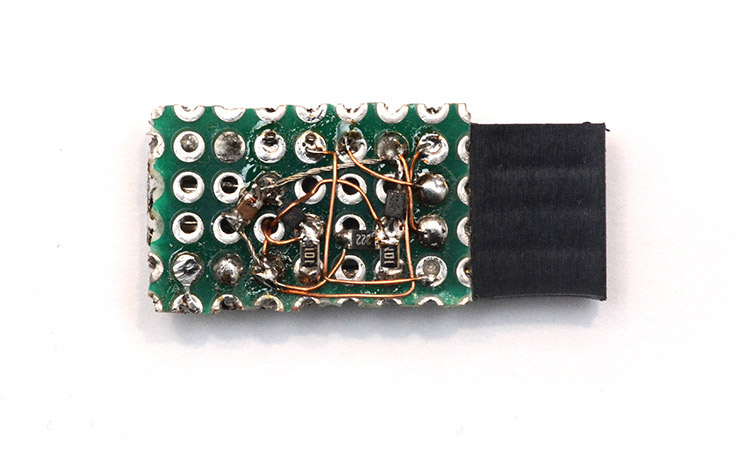
The pullup resistor is now mounted directly onto the board.
Pretty neat.
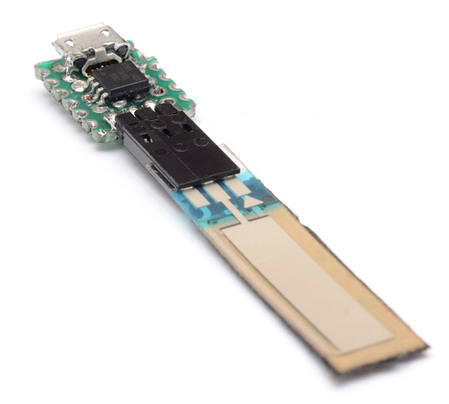
The black tape under the ribbon is to attach it to the harmonica. In fact, Brendan made a cool 3D printed case for the device to sit snugly in place.
This iteration worked reasonably well, all things considered. By setting the synth's bend range to +/- 3 semitones, the ribbon then has the same range as an actual harmonica.
But it still suffered from the problem of exact pitches being difficult to hit. If one end is no bend, and the other is -3 bend, trying to hit a -1 bend directly is almost impossible without a bit of wobbling around. A possible solution is to mount ridges onto the ribbon. The Yamaha KX5 has a pitch-bend ribbon controller, and it too has a ridge in the middle to help you find the zero point.
There was some further experimentation along these lines, and there may be a viable solution within ribbons with ridges, but what's really needed is a way to jump to a specific bend directly. We decided to head back to the PSP joystick, but this time use both of its dimensions.
Construction III
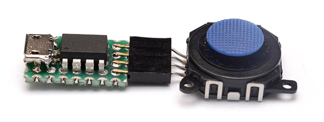
To read both axes of the joystick, we need to make two analog measurements. While technically possible, modifying the previous board to break out another pin without compromising the ability to fit a test clip over the chip seemed daunting, so I decided to make a fresh board for this. Construction followed pretty much the same pattern as before, if slightly messier this time round.
I decided to use a through-mount ATtiny this time, partly to make clipping onto it easier, and partly so I didn't have to worry so much if anything else needs adding. The protoboard footprint is the same, but the circuit is slightly taller now.
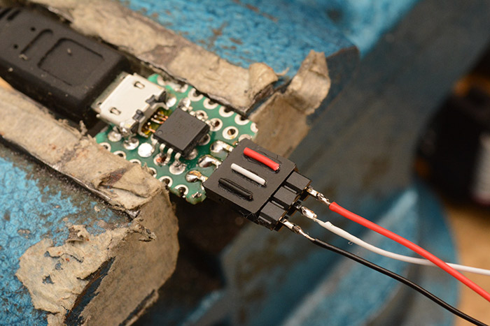
Onto the joystick I now soldered some thicker, single-core wire that can plug straight into a header socket. This is partly because soldering header pins directly onto the base would have increased the height a fair bit. The circuit can now be used with a cable...
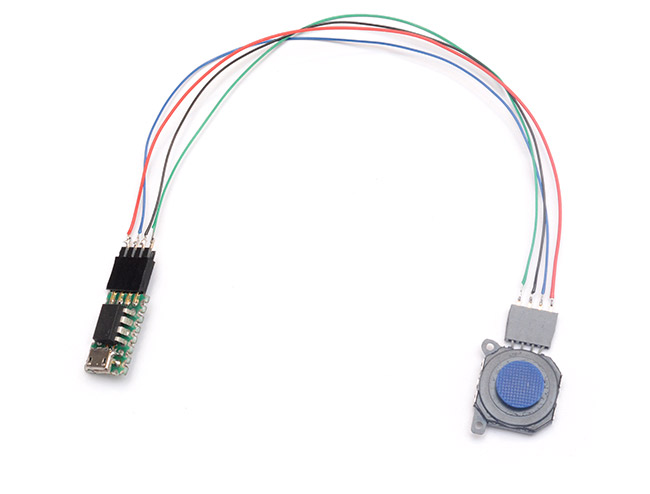
...or plugged in directly.
How should we make use of a 2D joystick for pitch bending? Well, the idea was to have each of the four directions correspond to a specific bend. That is, pushing to the right bends down one semitone, pushing to the left bends down two semitones, and pulling towards yourself bends down three. This means each bend can have a hard stop, so that when you want it to be dead on tune it's easy, but at the same time the bends can be eased into, unlike a button. The fourth direction we decided to make two semitones up, although it's unclear how useful that will be.
To implement this in software is slightly harder than before. So, we make two analog readings, one for each direction. We then need to decide which quadrant it's in, and scale the values accordingly. But, putting a hard line between the quadrants would cause some weird disjointed effects around the centre point, as well as sudden transitions if you roll from one bend to the next. The best way to do this would be to trigonometrically average the stick position, which would allow us to smoothly move between one bend and another, but it's almost certainly out of reach with the ATtiny85, which, remember, is still doing its software implementation of USB.
I decided to linearly interpolate each direction independently, then average their bend result. When rotating around the perimeter, the changes are not very linear, but this is computationally much simpler, and is perfectly usable for the four bend directions. In fact, to ensure that pushing a certain way fully ends up in tune, we'd already planned on making a small cross-shaped guide for the joystick.
(To illustrate why linear averaging doesn't work too well for diagonals, consider the following. The stick is at 45 degrees, between the three-down and the two-down positions. The x-axis reads cos(45deg) * -2 = -1.41 and the y-axis reads cos(45deg) * -3 = -2.12, so their average is -1.77, instead of the -2.5 we might have expected.)
In order to turn the readings into a single bend number with the fewest operations, I decided to prototype the floating-point code in Javascript. The pitch-bend amount is just a 14-bit number. Javascript, thanks to the Web MIDI API, can read this number. I configured the joystick to send each reading as an unedited number on a separate midi channel, and then did all of the processing in Javascript.
This made for quite a fun development environment. And, since we can also do MIDI-out in JS, I was able to pipe the corrected bend value back into a synthesizer for testing. I measured the absolute voltages of the joystick (they're nowhere near the power rails) and calculated some coefficients from them to do our scaling. Once the code was finished, I could copy and paste the main block directly into the C program for the ATtiny, since the syntax is almost the same.
Pitchbend values aren't inherently linked to semitone values; the only information carried is a fraction or percentage of the maximum bend. To have one bend of -3 semitones, the synth needs to be configured to have a maximum bend range of 3 (or more, but extending the range too far reduces resolution). Then, to have a one-semitone bend, we send a pitchbend value of 33.3%.
When you release the joystick, it needs to send a bend amount of exactly zero. I found there was a fair bit of variation to the position it snapped back to, necessitating the need for a dead-zone, within which the pitchbender always reads zero, and smoothly starts to bend as it leaves. Similarly it would be frustrating to hit the end of the joystick's travel and be slightly sharp or flat. So we set a hard limit, just shy of the end of the travel, beyond which it will bend no more. And repeat this for each bend direction.
After measuring some numbers and doing a few calculations, my code for turning the ADC readings into a 14-bit bend amount looked something like this:
// val1 = adc_reading(1) [0...1024]
// val2 = adc_reading(2) [0...1024]

int16_t bend1 = 0;
int16_t bend2 = 0;
int16_t bend = 0;

if (val1 <=478 ) {
  bend1 = (val1-478)  *34.13333333333333; // -3 semitones
} else if (val1>=577) {
  bend1 = (577-val1) *-22.755555555555553; // 2 semitones up
  if (bend1 > 5461) bend1=5461;
} else bend1=0;

if (val2 <=484 ) {
  bend2 = (484-val2) *-9.416091954022988; // 1 semitone down
  if (bend2 <-2731) bend2=-2731;
}else if (val2>=542) {
  bend2 = (542-val2) *19.504761904761903; // 2 semitones down
  if (bend2 < -5461) bend2=-5461;
} else bend2=0;

bend = (1<<14)/2 + (bend1 + bend2)

if (bend>(1<<14)) bend=(1<<14);
else if (bend <0) bend=0;

// pitchbend_send( bend )
Two floating-point multiplications per iteration, which should be fine. Of course as soon as we had a functional unit, and a chance to play with it, it was clear that the bend directions should be swapped, which meant recalculating those numbers. Luckily I still had my tool to do this, but the process was not very streamlined – yet.
Brendan was pretty pleased with this unit. It too got a 3D printed case (I forgot to get a picture of it) and after some practice, Brendan got pretty good with it. Which led to the next phase... making a whole bunch of them.
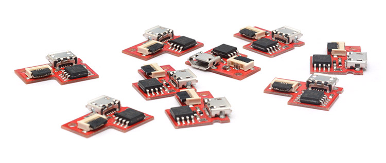
Constructions IV through LIV
Brendan sells an assortment of harmonica accessories already so he was pretty keen to market this device. I lean towards the opinion that selling electronic gadgets to extremely niche markets is never going to make much money, but that's a pretty boring opinion, so for a change, I decided to roll with this, even if purely for the experience.There's two things needed to scale it up:
- Improve the software on the tiny85 to allow customization
- Design and order a handful of printed circuit boards of the device
I figured that there's a whole load of things the joystick might be useful for aside from this exact configuration, and at the very least the bend ranges for each direction should be configurable. I also anticipated that the calibration numbers in the block of code above would probably vary from one joystick to the next, so being able to set those without reprogramming it would be a valuable addition.
There are pretty much two approaches to this software thing, either add (or write) a bootloader to allow firmware updates, or have the device configurable via midi messages. The bootloader is the most scalable, since once it's working we could deploy any new features remotely, and without dismantling anything. I was cautious about using a generic usb bootloader though, since one of the difficulties is finding a safe way to trigger it. Usually you'd have a jumper or a switch, or perhaps a timeout after it's connected. Neither of those sounds appealing, since we're out of spare pins, and having to wait after plugging it in would suck.
Another downside to a generic usb bootloader is that it would almost certainly require the end user to install special software. Which sucks.
So, something I've wanted to do for ages is a bootloader that works over USB-MIDI SysEx. SysEx is a protocol for sending binary data over MIDI. And MIDI over USB is a driverless, class compliant thing, which is completely platform agnostic. So there's a way to tunnel binary data to the device even when it's plugged in normally, without needing any extra buttons, timeouts, or special software.
The problem, however, is the same as any bootloader that uses a non-trivial protocol: having the protocol implementation in the same application image you're trying to update. A common solution is to have an intermediate memory bootloader, which uses the main application's protocol stack to download the image to, say, an external eeprom, then once it's verified the image (checksum etc) can trigger the bootloader which only needs to load data out of the eeprom and into the main memory. Of course in our case this option's completely out of the window since we haven't got any external memory, and the main image takes up more than half of the flash.
Another solution, such as the one I took when writing kiloboot, is to squeeze the entire protocol stack into the bootloader section, so you essentially have it twice. I'm not sure it would really work for our situation (or it's pretty much the same as using a generic usb bootloader). But a really attractive idea is to have the bootloader not update the protocol stack at all. The more I thought about this, the more it made sense: a MIDI device has a MIDI in, and a MIDI out. It doesn't need the USB for anything else. So we could write a USB-MIDI program that does everything a USB-MIDI device should do, except dealing with the messages. These could get passed to function pointers, like a tiny interrupt vector table, which would call code to do things that resided in the other half of program memory.
In this configuration, SysEx coming in could get detected, and the program could then start rewriting the program memory where the good stuff happens, while leaving the USB-MIDI stack untouched. Even if the firmware update failed, the device would still have enough of its code left to re-load the firmware image and repair itself. Neat!
Unfortunately, all of that sounded like a colossal amount of work, and I postponed it to a future date. Instead, I went with the more realistic option of using sysex to write configuration data into the on-board 512-byte eeprom.
There are many things the device could be configured to do. Instead of pitchbend, it could send continuous controller values, which could be a different controller for each direction, or four different controllers, or one controller in the same way the pitchbend is currently done. I also expect it would be very useful to be able to change the pitch-bend amounts and directions. I made a start on this, but since this would take some time I decided to work on it after ordering the circuit boards, since there was bound to be a few weeks of waiting after the order had gone through.
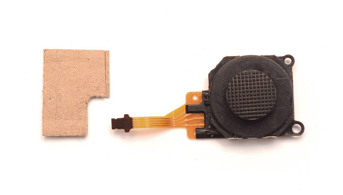
So – mass manufacturing of hardware. The first and most obvious improvement was switching to the PSP 3000 joystick. This is physically identical to the 1000, but has a ZIF connector / ribbon cable, which saves having to hand-solder things.
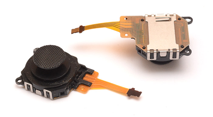
It unfortunately has a different shaped cap, but the mount for this cap is identical to the 1000 so they can be swapped over.
One thing to be sure of is getting the right connector for that ribbon. Even if you measure the pitch and ribbon thickness, it's possible to order the wrong connector. As it turned out, the clasp on the first connector I ordered made it almost impossible to plug the cable in, as it interfered with the tabs sticking out sideways on the cable. There's half a dozen different designs of clasps for ZIF connectors, so I'm glad I ordered a few of them to find one that worked.
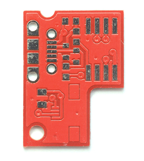
To lay out the PCB I used Eagle, and the design was pretty straight forward. Since the ribbon cable isn't centred, I decided to make my board lopsided too.
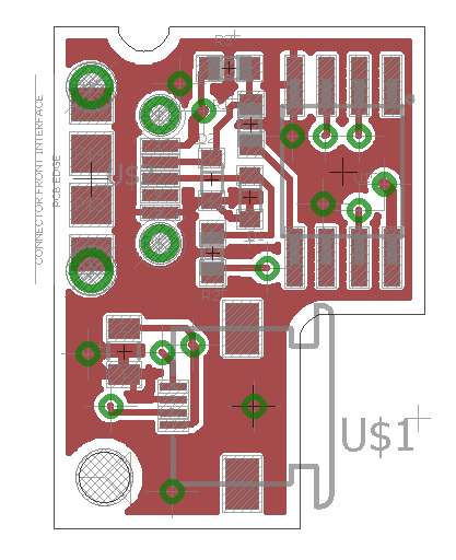
This nestles in nicely with the joystick, with the cable folded back on itself. Cardboard mockup:
In terms of ordering this thing, I decided to go with getting it made in China. I usually only get boards made in the UK, so this was a new experience for me, especially as we decided to get the boards assembled in China too. The company I chose was "pcbway.com" which had the cheapest initial quotes.
To be honest I was astounded at their manufacturing capabilities. They have more options to choose from than you can shake a stick at. Their turn-around times are shorter than anything you can get in this country, even when you factor in the delivery time. And their prices are much lower! They have the companies here beat on price, speed, and the variety of different boards they can make.
I wanted to try having the boards assembled there too, partly because those zif connectors are very fine pitch and made of a plastic that melts really easily (meaning, it's a pain to get it to reflow properly) and partly because their initial quote for assembly was lower than anything I'd seen before.
Of course, as soon as the files were uploaded for them to inspect things changed. Well, first of all they spotted that there was a 'mistake' in the silk-screen layer. Actually, it was just that I didn't add anything to the silk screen since the board was so tiny, but I was quite pleased they questioned that. But after they'd examined the assembly files I'd sent, their quote for assembly went up substantially. Still cheap, but not as crazy-low as they first promised.
Unlike when I've had boards assembled in the UK, they immediately spotted the microcontroller and asked for instructions for flashing it. I was impressed by how casually they added the cost of flashing the chips onto the BOM (something like 10 cents per chip). Even though I expected the software to change before delivery, I went with this anyway just to see how well they coped. I included the hex file, a text file with the fuse settings in it, and a batch file with the complete commands for avrdude. This seemed to satisfy them, and when the boards arrived the chips had indeed been flashed correctly.
Not all of the parts were available from their supplier. I had chosen zener diodes which were very small, to keep the footprint down, and also I'd specified the exact ZIF connector because I was worried about the tabs on the ribbon not fitting. They ordered these in from Mouser, and just added 14 days to the estimated delivery time. I guess that's fair enough, although I was a little miffed not to be getting their amazingly quick turn-around.
If you've never had boards assembled before, it's pretty similar to getting boards made, but you need to provide a BOM and a placement file. I prepared these in advance, but as it turns out their website has examples of these available so you know how to present them. Both can be exported from eagle easily, but there are all kinds of subtle mistakes to watch out for. I usually drop in parts with the wrong part number but the same footprint, as the board ends up the same, but I then need to remember to correct the part numbers when it comes to assembly. We also need to worry about the solder-paste layer. This needs to be approximately the same as the solder-mask, but each pad slightly bigger, depending on the part. In some situations (such as castellated boards) it's helpful to put long rectangles sticking out on the solder-paste layer which get wicked up the joint as it reflows.
In addition to the BOM and placement file, it's also helpful to provide an image or diagram of the assembly. I included a couple of screenshots from eagle along with the schematic, plus a hand-drawn diagram of the polarity of the diodes, but they actually asked for more. Even though there are only about three parts for which the polarization matters they wanted a clearer diagram with the part designators next to each one, which I guess is fair enough.
When assembly finally started, about 18 days in, they found a mistake on the boards. The solder resist layer was covering the pads for the ZIF connector!
They emailed me just as the assembly was about to begin. It was probably my fault for rushing through the critical final step of examining the gerbers for this sort of thing. Ultimately the problem may have spawned from the fact that for the ZIF connector, instead of laying it out from scratch, I did the usual thing of copying and pasting the basic idea from another connector that was mostly the same, and that source component may have had the error in it. Another source of error is the temptation to use polygons. Gerber files don't have support for polygons really, just flashed pads of squares and circles and the like. So if you add a polygon to your design, it will be mangled into a mess of tiny flashed shapes when you export to gerber. It's always best to avoid polygons, but when the design is small, and you're in a hurry, you can often get away with it. I did once have a similar problem, or at least I think I might have, on a different order a while back. I used a polygon on one of those awkwardly shaped surface-mount connectors, and when it came back from the manufacturer, it looked like the solder resist for that pad had been scraped off by hand. Possibly their software had mangled it, who knows.
For our boards here, well, the boards are so incredibly cheap to produce, and at such a quick turnaround, that it just isn't worth trying to scrape the layer off. Instead I gave the go-ahead to make the boards again with the problem fixed. This does set us back a few days, which isn't the end of the world, but is annoying, since if the mistake had been noticed sooner we could have re-made them while waiting for the parts to arrive.
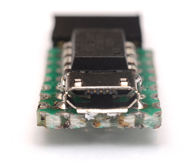
I took particular care over the choice of USB port, and the way it's soldered on. Many usb ports ask for tiny routed cutouts for their tabs to stick into, but the standard router bit for boards is a 2mm diameter, so this would probably mean paying extra to have those holes routed out. Even more so if they then need to be plated, since the routing usually comes after the hole plating. Perhaps I'm missing something, maybe you're just meant to have a series of small plated holes that link together. In the past I've sent off for boards from the UK and had them misunderstand the footprint of a USB connector and not do any cutouts at all, meaning I had to drill each board out by hand.
There are some USB connectors which are entirely surface-mount, but I feel like this is asking for trouble since there could be a fair bit of stress in its intended use, on the harmonica with the cable trailing. As you can see in the board image above, this time I just asked for a plated through hole big enough for the tab of the connector, and covered the entire hole in solder paste. This worked, and every USB connector was perfectly fine, but most of the boards had (harmless) stray spots of solder on the underside, probably as a result of this.
There was import duty to pay when they arrived, I'd expected this. Apparently if you go for HK Post or one of the other slow ones you can circumvent this, but I wasn't prepared to wait six weeks for the boards to arrive.
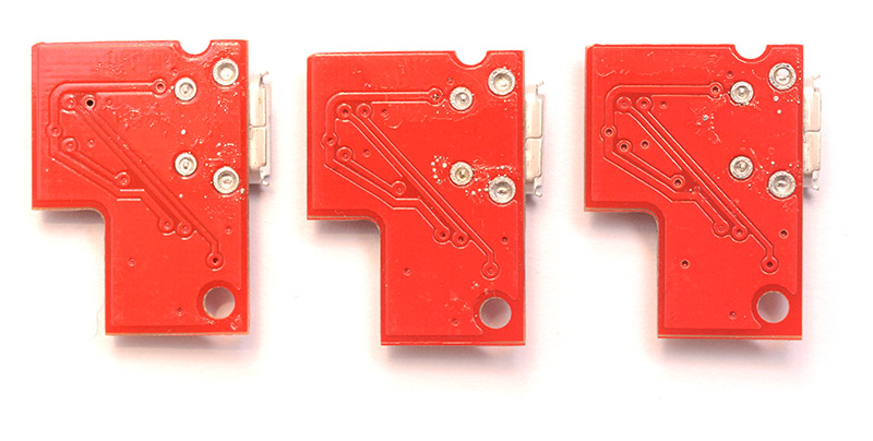
I grabbed a handful of the boards and tried them out, plugging the USB cable straight into a fresh board, exciting. They'd been flashed OK.
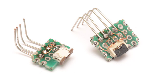
But, of the 50 boards I'd had assembled, three of them were unusable because of a soldering error. Perhaps the mask was too wide, perhaps their tolerances were not up to scratch, but on these three boards the ZIF connector pins were shorted together. Maybe I should contact the manufacturer and ask for a partial refund, I don't know. If it turns out we need these boards, I could manually fix the soldering.
In the picture above, the central two pins of the connector are bridged together. Hmmm.
Anyway, the boards mostly worked, but it became obvious that the joysticks plugging into them were too varied, and some of them were unable to hit the bends correctly as a result. I had two options here, re-flash them with a modified version of the code with slightly different, broader tolerances, or, finish what I was originally working on, which would let us calibrate each one perfectly.
Back to the Software
Obviously the correct decision was to finish the calibration code.
The very first thing we ought to accomplish is transferring binary data from the host computer to the device. SysEx is reasonably straight-forward: you send some starting sequence, a blob of binary data, then an ending character. MIDI is predominantly 7-bit, even though the protocol is 8-bit bytes. In this case, the ending character of a sysex blob has the most significant bit set, which means all of the 'binary data' has to be 7-bit data.
Add in the USB sandwich, of MIDI data being parcelled into 4-byte chunks. Most midi messages are two or three bytes, and over USB the extra byte is split into two nibbles, one a Cable Number, which is used for piping multiple midi streams through the same physical cable, and the other a "Code Index Number" which is usually the same as the status code of the midi message. Except during SysEx. In this case it's used as a flag to signify whether there is further SysEx data incoming. None of this is complicated – just tedious.
We might be tempted to send seven bytes missing their MSB, and an eighth byte that represents all the missing bits, but although that would be compact, it's much easier to pad things out a bit more. For a start the total amount of data we're sending is minute, so efficiency is of no concern (additionally, the EEPROM is very slow to write, so slowing down communication may even be beneficial). The data comes in by 4 byte chunks, of which only three bytes are payload, so let's just use three bytes to transfer two bytes of data.
Using avrdude it's possible to test this system working. I set up my usbMidiMessageIn() function (called by usbFunctionWriteOut(), when data arrives at the chip ) to spring into action when SysEx arrives, decode it back to 8-bit data and write it into the EEPROM. SysEx is supposed to start with a magic number representing the company who implemented the protocol, well, I'm not going to pay the MIDI foundation for the privilege, and went with 0x1234. Next, avrdude -U eeprom:r:"eeprombackup.bin":r will read out the EEPROM as binary data for us to examine and check it's all working.
So much for the easy part. Looking through the C code, we next need to collect all of the variables that may want changing over SysEx into a single struct. Although there are just eight 10-bit numbers that really matter, being the thresholds for the numbers coming out of the 10-bit ADC, I'd much rather transfer those floating point multiplication numbers across, to minimise processing on the chip. These numbers are derived from the 10-bit numbers and the bend directions and amounts.
struct {
  float up;
  float down;
  float left;
  float right;
  int16_t voltage[4];
  int16_t limit[4];
} bendAmount;
How is a floating point number represented as binary data? (The fun never stops...) We can examine it quickly, either by populating the struct, writing it to eeprom and reading out over avrdude, or forming a union between the floating point variable and a byte array and printing the results. Unsurprisingly, AVR-GCC is doing a software implementation of IEEE-754.
Downloading the binary data and shoving it into the struct is easy, so the ATtiny code is now done. The difficulty lies on the desktop software side. For its platform-agnostic joys, I (obviously) opted to write this in Javascript. Further fun arises as it transpires that for some ludicrous reason SysEx is a "security risk" to Chrome and requires even more effort than usual: the page cannot be hosted locally, the domain must be secured by TLS (not a problem for me, thanks to Let's Encrypt), and an additional pop-up box is shown to the user with a warning about SysEx. We also have to initiate the Web-MIDI API with a SysEx request otherwise it won't work. But apart from all those, it worked first time!
Now that binary data is going from Javascript to the ATtiny, (we're almost there!) we need to come up with the calibration numbers, work out the floating-point coefficients, and turn them into binary data in the IEEE-754 format. If we were working in C this would be a piece of cake. In the weakly typed world of JS though, we can't do a union. We have to manually re-implement this thing. I was deeply disappointed someone hadn't already done this for me; a few minutes of Googling turned up nothing. Lacking any better ideas, I implemented a hilarious brute-force approach, following an example designed to teach people about how floating-point works, which involved piecing together ones and zeros as a string. But it works. For the ranges we care about at least. Phew.
At last we had a framework in place. I could now flash all of the chips with the same code, and calibrate them individually with my Javascript tool. It would be trivial to add other features into this, an obvious one would be changing the MIDI channel it transmits on, but I did 95% of this software development in a single night and quite frankly at this point I wanted to go to bed.
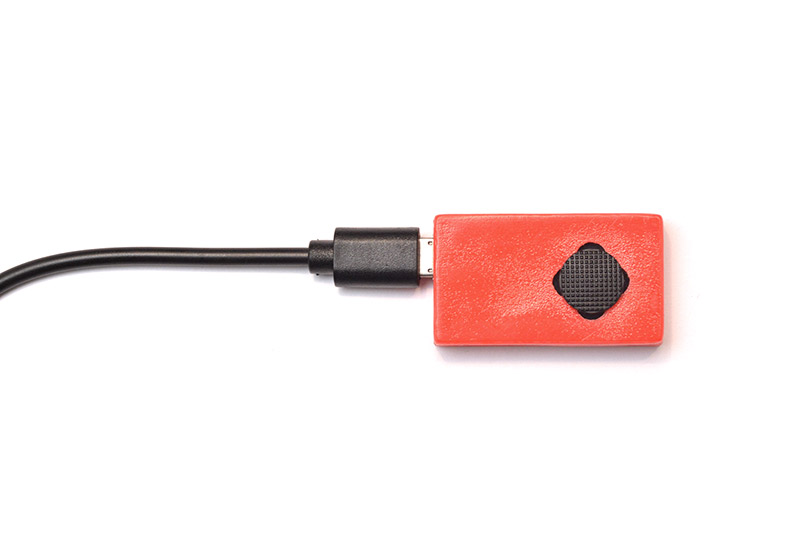
The final product
Finishing up the calibrate-able code means we can at last flash all of the boards and put them into neat 3D printed cases. The ones in these pictures are actually the penultimate prototype – Brendan made the final ones about a millimetre smaller.
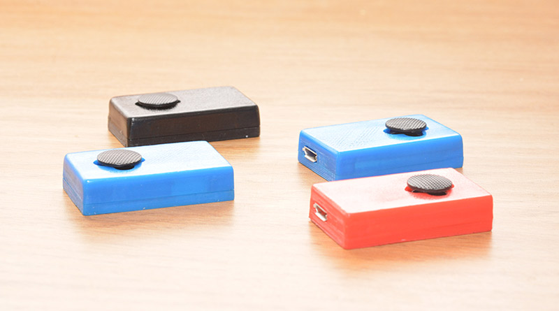
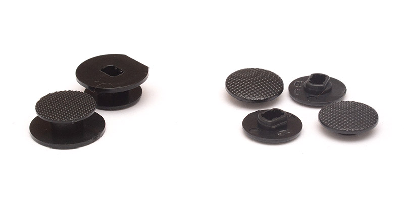
Interestingly, I'd ordered the replacement caps for the joystick from Aliexpress, and the first ones that arrived were unusable. They were slightly mis-moulded, which meant they didn't fit properly. I then ordered some more, from a different seller, which never arrived. Finally we ordered some from a UK supplier which actually turned up, and were perfectly usable.
Video
The calibration tool, and how to use it
- The tool is written in Javascript, so it shouldn't matter if you're running this on Mac, Windows or Linux. But it doesn't support touch-screen devices yet.
- Google Chrome is the only browser that supports Web-MIDI (as far as I know), so currently the tool will only work in Chrome.
- Due to security restrictions in Chrome, the tool will not work if you try to run it locally.
- Although MIDI devices are often technically hot-swappable, Chrome doesn't always play well with it. If in doubt, close Chrome, plug in the joystick, and open Chrome again.
The tool is hosted here.
It should prompt you to allow Chrome to access MIDI devices. After clicking yes, you should see the Mini Pitchbend Joystick listed at the top. Wiggling the joystick should display the pitchbend number it's currently sending as a 14-bit number and as a percentage.
To calibrate the device:
- Click "Toggle Calibration Mode" and wiggle the joystick a bit. It should show the raw joystick voltages as black diamonds on the graph.
- The yellow regions are the calibration numbers ( they'll be completely wrong to begin with because the tool doesn't yet read out the previous calibration numbers ). You should be able to drag the edges of the yellow rectangles left and right.
- For each joystick direction, move the yellow region so that the diamond is safely outside the region when the joystick is at its extreme. You want a safe amount of overshoot, because depending on the angle and pressure on the joystick it can vary a fair bit. About the width of the black diamond seems a fair margin. Whenever the joystick overshoots the number, it clips it to be perfectly in tune, so it's better to be on the safe side.
- Next do the middle bits, the dead zones. Whenever you release the joystick from any direction, the diamonds should be safely out of the yellow. You might find that for one direction the dead zone needs to be much bigger than the other, this is extremely variable from one joystick to the next.
- When you're happy with the calibration numbers, click "calculate" and then click "write to device". Then click "toggle calibration mode" to get it back to normal, and look at the numbers it's sending now. You should be able to hit -33.3%, +66.6%, -66.6% and -100.0% perfectly, and always return to 0% when released. If you're not happy with it, you can repeat steps 1 to 5 as many times as you like.
If you accidentally leave it in calibration mode, it won't work as a normal pitchbender, but unplugging the USB and plugging it in again will reset it back to normal.
Every time you click "write to device" it saves it permanently onto the pitchbender, but since the tool can't currently read out the numbers again, if you close the browser and open it again you'll have to start over.
Advanced: If you're not happy with the default bends and their directions, the numbers in the boxes in each corner of the calibration graph can be changed. They can even be changed to fractions of a semitone, and it should still work, just as long as all of these numbers are less than or equal to the "synth bend range" parameter at the top. This can be changed, too, but you need to change it at the synthesizer as well, of course. Also, the bigger the bend range, the lower the resolution of the smaller bends. So, for instance, setting the bend range to be 8 and then configuring one direction to bend just one semitone is a probably going to lead to it being slightly out of tune. When you leave calibration mode, be sure to check the percentages coming in, it should give a clear idea of if there's a problem.
Source Code
I have uploaded the source code for the device onto GitHub. The main loop might be pretty incomprehensible on its own as the whole idea was to make the calculation general enough that by changing the struct values we could change the bend target of each joystick direction. The code snippet up above might help explain what's going on.The calibration tool was written very quickly, and is probably glitchy. I don't think it's possible to brick a joystick using it, but if things go wrong, it should always be possible to unplug everything, start over, and send new calibration numbers to it. If junk gets written to the EEPROM, the pitchbender might not send anything because if every calculation saturates, it will think the joystick isn't moving. It should still be possible to get it into calibration mode though.
The 'dec to IEEE-754' function is correct over the range of numbers we're expecting, but probably won't work for anything else.