
Thermal Paper Polaroid
4 Apr 2018Progress: Complete
It feels like only the other day I was going on about an instant camera that uses thermal paper being one of my abandoned dreams. I abandoned it because I found out it had already been done, and isn't particularly hard. But! Soon after, I decided that that's a terrible way to see things, and if we stuck by that, we'd never get much done, let alone learn anything.
So here is my attempt at an instant camera that prints onto thermal paper.
This project was partly done as a collaboration with Tom, who knows a lot about Linux and whose face is visible in some of the pictures.
The Prototype
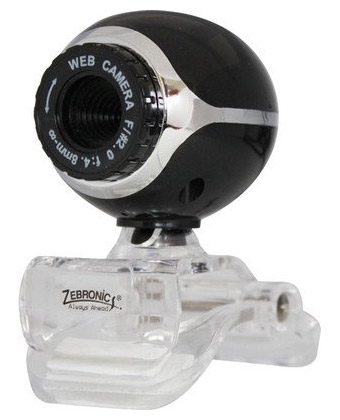
First two things I ordered were a webcam, that cost £1.99 including postage, and a thermal printer.
The printer cost £34. I did not go for the cheapest one available, instead I opted for the smallest one available, which happened to be bluetooth enabled. I never planned on using the bluetooth function, but it's still a good choice of printer, as it supports USB and RS232, is small by the standards of thermal printers, and includes a reasonably big battery too.
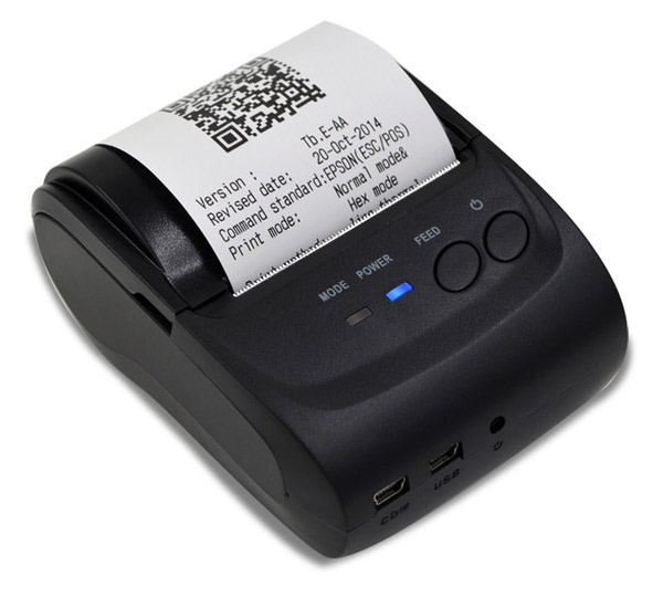
I don't know much about how you're supposed to install printers on Linux, there's something called CUPS which I didn't care to learn much about, but plugging the thermal printer into the USB port on my laptop caused a new device to appear as /dev/usb/lp0. Piping some text to this device prints it out – that was easy!
echo "Hello!" > /dev/usb/lp0
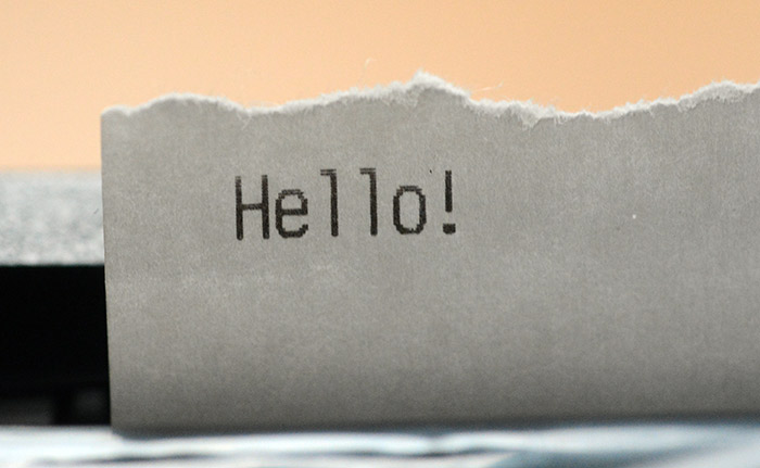
That text is printed in the default font of the printer. A line-feed character causes it to feed paper. But for anything other than that we need to use escape codes. Apparently the escape codes we need to know about are referred to as ESC/POS.
After googling for a reference for these (I am still not convinced if there is more than one standard, or that only some codes are supported) we started to have some success. It's even possible to pipe standard input to the device, then manually type the command.
cat > /dev/usb/lp0
After buggering around with this for a while, next task was to grab an image from the webcam. The very easiest way to do this is with ffmpeg, where you can ask it to stream just one frame.
ffmpeg -f video4linux2 -video_size 640x480 -i /dev/video0 -vframes 1 /tmp/blaa.png
How to send this to the printer? Luckily, someone's already written a python script to generate the ESC/POS sequence for bitmap printing.
There were some hickups, and hickups usually mean wasting a lot of thermal paper, but eventually we hit success. Once a bitmap image was successfully printed, the concept is proven and we know it'll all work with enough tweaking.
To the Pi
Up next, port it across to a raspberry pi. This is a bog standard pi running raspbian.Ffmpeg isn't present in the raspbian repositories, but there's avconv which is essentially the same thing. Python scripts are easy to install. One unexpected problem is that the Pi incorrectly identified the pixel format of the webcam and the colours came out all wrong, purple and green everywhere. We needed to manually specify the pixel format as RGB24 for it to look right. But it's all going to be black and white in the end.
Since raspbian is basically debian, there really wasn't much else to do here. But there's a big problem: it's unacceptably slow. Slow to boot, slow to shoot, slow to convert the image and slow to send it to the printer. There's a lot of room for improvement!
As an interesting experiment, we installed a bash script as a one-shot service to see how soon in the boot process we could get it to run and take a picture. To do this we just made a unit file that'll be loaded by systemd with Type=oneshot and Before=networking.service. I'm not sure if there's a way to get it to run even sooner in the process, there probably is.
But this was pretty awful in terms of speed, it took about 40 seconds from power-on until the picture was taken. I added another line to see if it's the picture-taking itself that's slow. Piping urandom to the frame buffer means the screen fills with junk when the script starts. The script looked like this:
#!/bin/bash -e

cat /dev/urandom > /dev/fb0 || true

/usr/bin/avconv -f video4linux2 -pix_fmt rgb24 -video_size 640x480 -i /dev/video0 -vframes 1 /home/pi/blaa.png
By the time we reached the end of the first roll of paper, the development process and the number of incorrect image printing attempts was hilariously documented all over the floor. I decided to stick it on the wall.
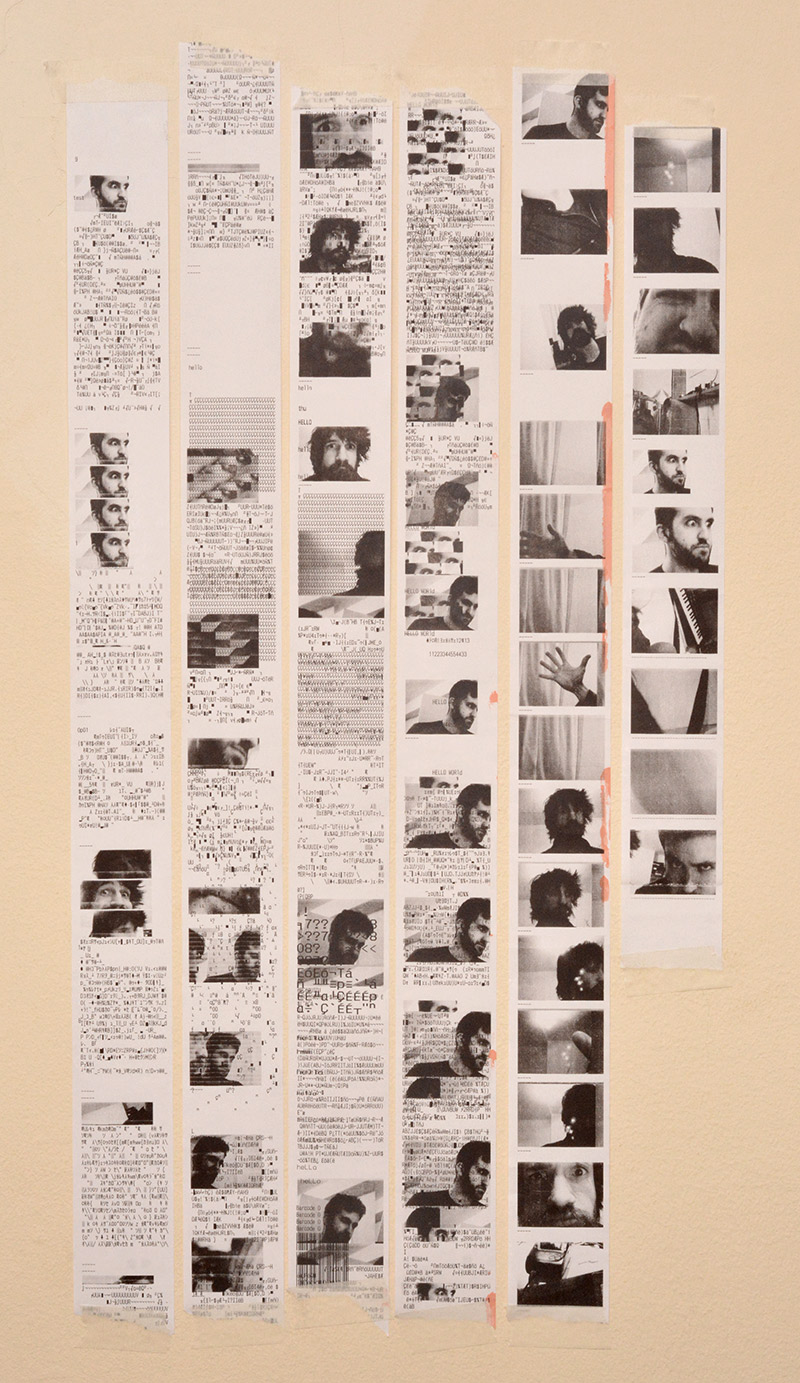
An accidentally artistic endeavour. What's up with all the mangled frames? Sometimes it would miss whatever header it needed and spit out the binary data as if it were ascii. There's even a barcode in there!
Before pursuing Embedded Linux any further, it was time to find a donor camera...
To the Polaroid
It has to be a polaroid. Much as I'd love to stick the mechanism in an old rangefinder, a polaroid it has to be. Some searching of eBay found a broken one.
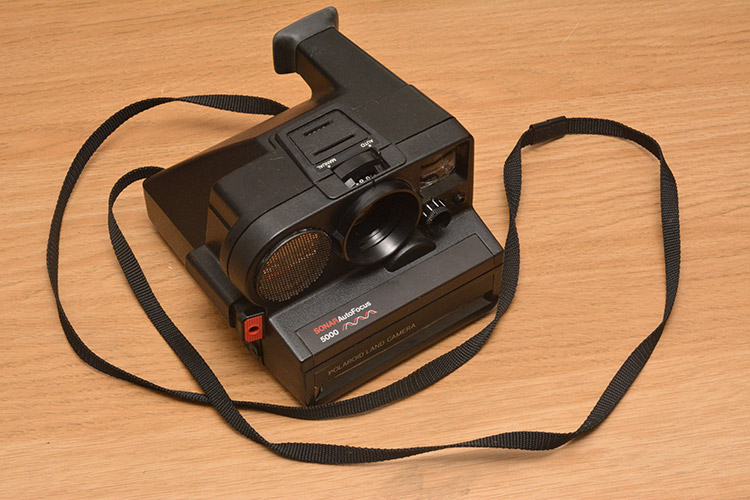
Combining a Polaroid with a Pi does also mean that the most tempting (and most awful) amalgamation-based name would be "Pilaroid" – a horrific monstrosity that somehow manages to conjure up images of both haemorrhoids and piles. Eyuch! I think I'll stick with "Thermal Printer Instant Camera"...
Now for the fun step, pulling this thing apart and gutting it.
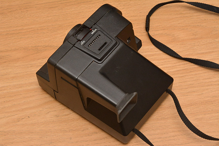
There's a flash mount, and a lever to switch between autofocus and manual.
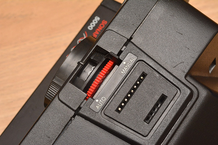
In manual mode the focus ring is covered up. Around the flash mount is the first piece of plastic we can remove.
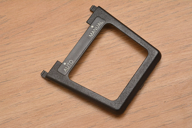
Now we're starting to see something really impressive, and it gets better. The entire camera is assembled using plastic tabs. Not a single screw in the entire construction!
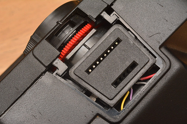
The front panel clicks open for loading the film, and behind it are more tabs that can be released using a flat screwdriver.
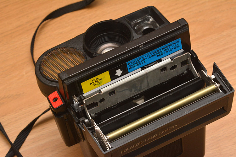
This detaches the front panel.
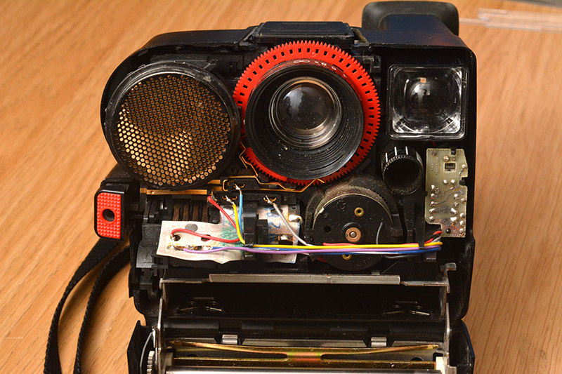
The central lens is the picture-taking one. To the left we have the piezoelectric ultrasonic transducer that's used for distance measurement, to the right there's the viewfinder front element, and the small lens in a dark tube underneath that is the light sensor.
At this point, with some encouragement, the entire camera can be slid out of its housing.
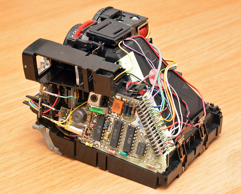
Yummy! Through-mount parts, PCBs without solder-resist, and dupont connectors everywhere.
I love cameras. They're a delicious mix of optics, mechanics, electronics, and electromechanics. Almost all of the mechanisms here are plastic. Even the lenses are plastic. Just how many injection-moulded parts are there? And still not a screw to be seen.
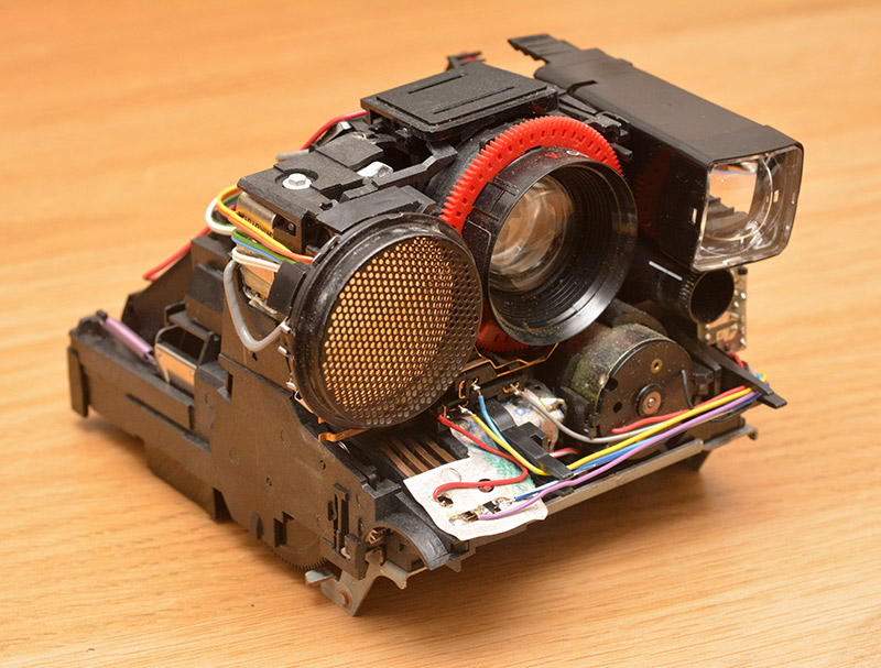
Wait, there's one, a bolt on the top of the solenoid for the shutter mechanism. But that solenoid is probably a drop-in part.
The viewfinder comes away, and now we can see there's a flexible PCB involved. But it's not kapton-based, it's printed on paper!
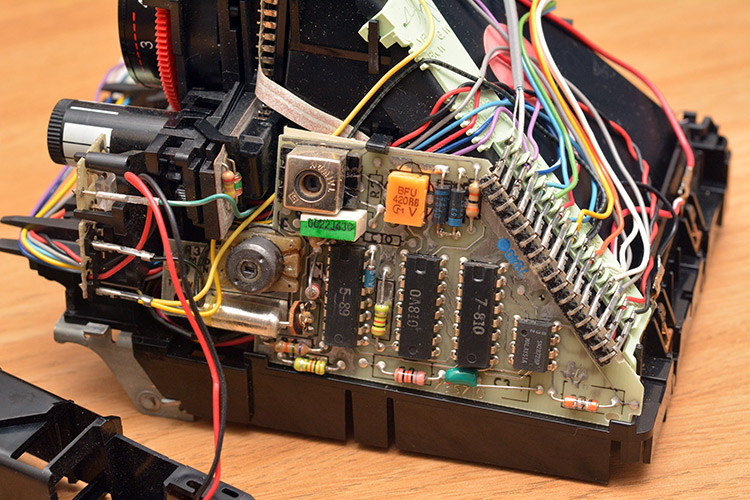
The green plastic wiring guide has labels on it with the wire colours. Cute. But all this electronics has to go...
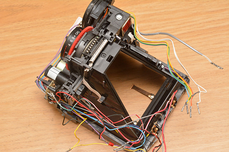
I pulled out the big, trapezoid front-surface mirror. It wasn't worth trying to take a picture of it though.
The large copper tabs are what originally connected to the battery that's contained within the SX-70 film package. I tried powering it up with 6V (before the pulling the electronics apart), but I couldn't get it to do anything really. Either because there's a mechanical interlock somewhere, or perhaps to do with the fact that the listing on eBay did specify the camera was broken.
Next we remove the rest of the front panel, the autofocus mechanism and the side plate that's both part of the film feed mechanism and the shutter button.
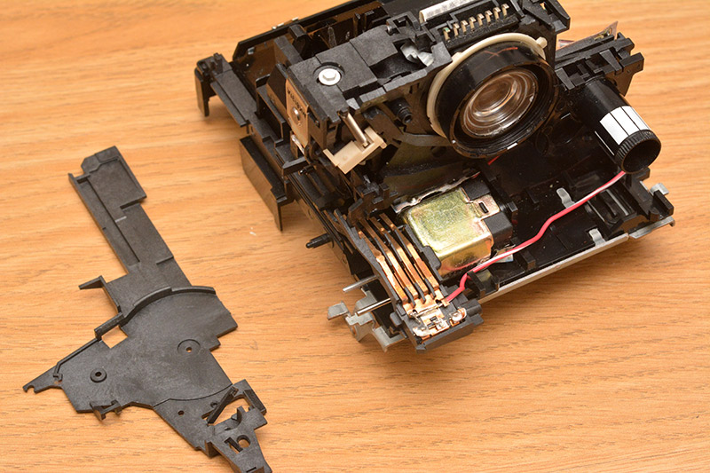
Not shown in the picture above are the many gears and levers that were supported by the side plate. The mechanism, entirely in plastic, mechanically links the shutter actuations to a counter that advances when a picture is taken. There's a little window on the back of the camera with remaining shots displayed, presumably this is also reset when the film is loaded, although I didn't trace out all of the mechanical workings here. The feed motor engages both the rollers at the front and probably a part of the film cartridge. A few of the gears were made of metal, I suppose there's quite a lot of force involved in squeezing the film through the rollers. I didn't pay much attention to this part as I planned to strip it all out anyway; the brushless motor used by the thermal printer is much more compact.
It's possible to actuate the shutter at this point, by working some of the levers back and forth. I'm particularly interested in the way the exposure compensation is performed. The timing is electronic, based on an analog circuit and a light sensor, but the compensation ring physically moves the pivot point of the lever arm for the shutter leaves, thus altering the timings. It's something I've seen before, and I never know whether to think of it as ingenious or stingy.
The brass tabs at the bottom are all contacts and detectors, I cut away many of the wires to them. They're all for detecting the limit positions of various mechanical linkages.
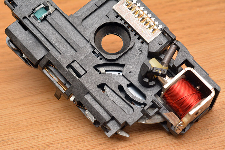
Above is the shutter mechanism in isolation. I definitely wanted this to be working in the final thing. There was rather a lot of work involved with disassembling it to this point, including the removal of the main lens elements. Since they're plastic, and cannot be used in the final thing because they're completely the wrong focal length, I ended up drilling through them. It was a weird experience. There were only two elements, and they were both gummy plastic.
The leaf shutter only has two blades, closing in a diamond pattern. As part of the closing mechanism it also covers up a secondary light sensor, possibly for calibration purposes. The camera has a fixed aperture.
I had to cut through the flex PCB, it was all soldered down anyway. Linking the shutter solenoid to 6V makes it fire with a satisfying click, but the mechanism is locking since it would normally want to be closed most of the time. I found the tab that controlled this and snapped it off, so that the solenoid is sprung open and just clicks closed momentarily when powered. Even though the webcam only grabs one frame, it'll need to be exposed to light all the time in order to get the exposure right, as like all webcams it does a kind of rolling average of light levels. The shutter click can take place right after the image is taken.
With that completed, reassembly can begin, but not before we observe the rather sad husk of the instant camera.
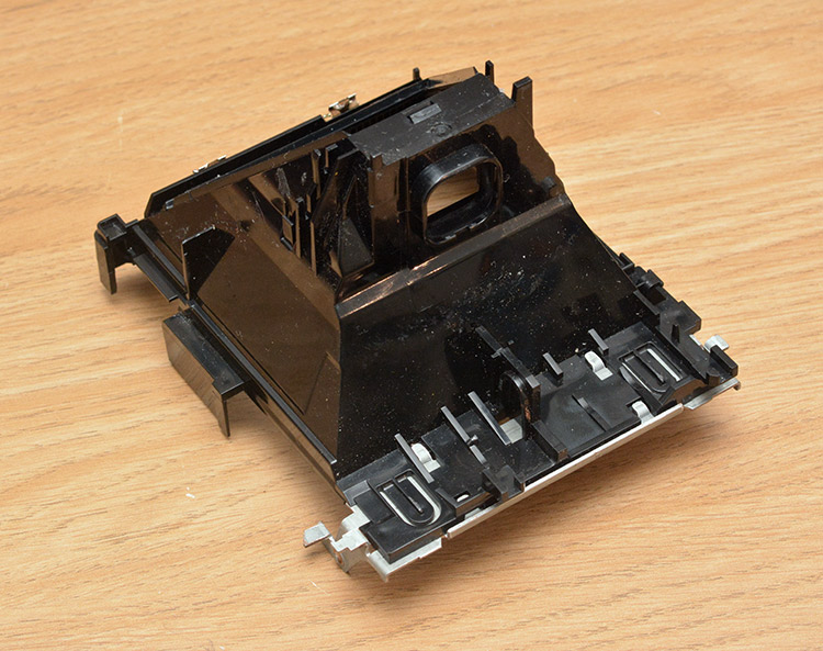
As part of the reassembly, I broke open the webcam and fitted it into the shell of where the lenses used to be. It was quite important to have a live view while doing this, in order to make sure that the view wasn't unintentionally vignetted. I also laser-cut out a disk of acrylic the same diameter as the original front element, in case it looks odd without a big lump of plastic there. (I never did make my mind up about whether to fit it though.)
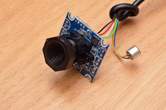
For £1.99, it's a pretty good webcam. Even came with a microphone. The focus needed to be fixed at about two metres. There's quite a big depth of field, which when combined with the exceedingly low resolution of the printed images gives us just about even sharpness at all distances. I sawed off the octagonal front to the hood as part of the attachment to the main camera body, you can probably guess what was involved: craft knives, drilling and lots of glue.
At this point, I also began working on fitting the thermal print head into the body. This was extremely tedious, probably ten hours of sawing, drilling and gluing, and I didn't get many pictures on the way. Pictures of the final thing, further down this page, should hopefully give an idea of what was involved.
Incidentally, since the print head would have to be mounted upside-down, I decided to mount the camera upside-down too, thus neatly avoiding an extra processing step.
The Camera Plan
Plans were made, certainly, but they kept changing. I did notice that the thermal printer circuit board was powered by a chip labelled GD32F103 – sounds suspiciously like an STM32F103 – and after looking it up, yes, it's a Chinese clone of that chip by a company called GigaDevices. So there's an ARM Cortex M0 on board. The most tempting thing would be to reprogram this with our own code that directly interfaced with the camera... but it's not going to happen, I just don't have the effort to fully reverse engineer this thing.
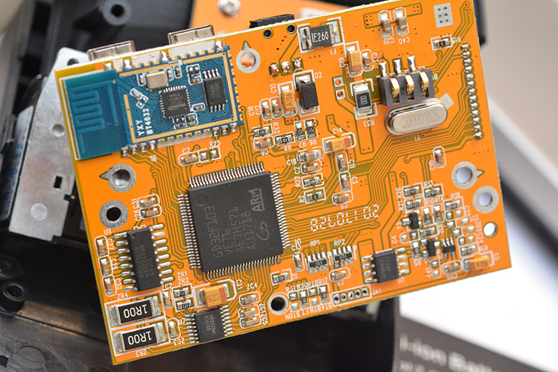
I did consider reprogramming it for another reason, though. Part of the problem is that we're going to use a Raspberry Pi Zero, which only has one USB port. We have two devices we want to talk to, both using USB. Not only that, but enumerating the USB devices is slower than some other methods of talking to peripherals.
I know there's a Pi Camera and I probably should have been using it, but it's overkill, it's expensive and aside from anything else I'd already fitted that USB webcam into the Polaroid at this point. So the camera has to be USB, but the printer could potentially be driven by the UART port. There's an RS-232 transceiver chip on the circuit board, if we solder to the legs of this we can talk to it at normal voltage levels.

At this point I'd prepared from earlier a binary blob that contained both a bitmap image of my face, and the escape codes necessary to pipe the whole blob to /dev/usb/lp0 and have it print as expected. Now with the serial port exposed, I tried piping that same binary blob there, and everything functioned perfectly! Except for one major flaw. The baud rate is fixed, and the device prints at a speed that empties the buffer faster than it can refill. So when printing a picture by this method, it has to stop and wait for more data halfway through. Since it's printing via a heating element, stopping halfway through means a horrible burnt line across the image. Darn!
This had me scratching my head for days (I really didn't want to have to stick a USB hub in there). If only we could extract the firmware image of the thermal printer, search for the setting of the particular registers relating to UART baud rate, twiddle a few bits and write the image back, it might be possible to speed up the data transfer and make UART image printing practical. There's a suspicious looking header at the bottom of the board. I was hoping this might be JTAG, or the ST-link interface, but tracing out the pins and checking the datasheet for the part suggests this is something else, perhaps a protocol for a custom bootloader they've installed.
I spent a long time trying to work my way around the limitations without any success. I tried one other thing, scoping the communication between the bluetooth module and the main chip. I thought that perhaps if this was at a higher baud rate than the exposed interface we might get away with squirting something into there. But there's so much comms on that data line, AT commands and whatnot, all stuff we would have to emulate to get the chip to believe it was still talking to the bluetooth module, that eventually I gave up on this too.
So we'll use a USB hub. Enumerating it adds a split second to the boot time, but we'll have to cope.
The Camera Plan (continued)
Here's the inputs that the original polaroid had: half-depress of the shutter, full depress of the shutter. There were also a bunch of internal limit switches.
Here's the outputs it had: an LED under the viewfinder, an autofocus motor, a shutter solenoid, and of course the film feed motor.
We want this thing to be super easy to use, just pick it up, press the button and a picture comes out. It needs to be quick and responsive. It also needs to have a decent battery life, and hopefully very low standby consumption. I came up with the following idea:
- We'll add a control chip, probably an ATtiny which can boot instantly on a pin change interrupt. It'll listen to the shutter switches and have control over the booting of the Pi.
- The Pi can shutdown to enter a low power mode (note, due to hardware, it cannot enter a standby/suspend to ram mode). The ATtiny can wake it up by toggling the run pin.
- While the Pi boots (assuming we can get the boot time down to ~1 second) the ATtiny can rack the autofocus motor back and forwards. So, the user has pressed the half-depress of the shutter button, it acts as if it's focusing, then signals that it's ready when the Pi has booted.
- Full depress of the button causes a picture to be taken, and for user feedback the shutter solenoid fires. Then, the printer is sent the image and the whole system can shutdown, with just the ATtiny in deep sleep waiting for the pin change.
This will require quite a few links between the ATtiny and Raspberry Pi, along with an H-bridge driver for the autofocus motor (and reuse of its limit switches) plus a single mosfet driver for the solenoid.
Crucial to this whole idea is that the Pi can boot quickly. It would also be useful if it wasn't running any unnecessary software, as that'll just slow it down during the image conversion process and also waste battery power.
Time to get our Embedded Hat on.
Buildroot
To be really hardcore we could go bare metal. No operating system, just our code running natively on the processor. We'd still need to make use of the Raspberry Pi firmware, which is what runs on the GPU in order to bootload the main software. I think it's probably not all that hard to do this, but given that we're using USB drivers, and python libraries, it's probably a lot more work than the other options.
Raspbian is the OS that's designed for Raspberry Pi, and it's honestly a bit boring because it's basically Debian. We're not getting the full Embedded Linux experience. I mean, the fact that there's a compiler on the device, and a package manager, it's about as high-level an embedded system can get. It's also really bloated, for what we want to do.
The usual approach to embedded software is cross-compiling source code from a desktop computer and flashing the image onto the device. We want Linux, as the kernel drivers make interfacing everything easy, but we don't want everything else. It's possible to cross-compile the whole of the linux kernel from scratch, adding just the modules needed, but it takes a lot of configuration. There's an easier option – buildroot.
Buildroot is generic and supports lots of different hardware platforms. By running make nconfig (or menuconfig if you prefer) we get a nice menu where we can select everything from target architecture to included packages. But, life is even easier than that, because by running make raspberrypi0_defconfig the important menu options will all get filled out for us. This even adds in the raspberry pi bootcode, and selects the modified kernel image from the raspberry pi foundation.
It's interesting to look through the folder structure at all the different boards that are supported like this. There are quite a few embedded linux boards I didn't know about, some of which might even have been more appropriate for this project (but then again, at £4, the Pi Zero is hard to beat).
Running make (or make all) starts to download the sources and begins the compilation process. This takes some time. On my laptop the compile time was about 43 minutes. If we change a setting in the menu, it's possible that we have to clean and rebuild again, which means another 43 minutes of waiting. It's not entirely clear what changes need a complete rebuild, but pretty much everything regarding the target architecture and the filesystem layout is probably a good guess.
There is an interesting option, to link everything into the inital ram filesystem (initramfs). That's (as I understand it) a temporary filesystem in RAM that's used at the very beginning of the boot process in order to load the kernel image, but if we include everything in the ramfs, the whole of the operating system and file structure can be kept in ram. This means that after the boot process, the card can even be pulled out, and everything will keep working. It also means the system is stateless, as the card is basically read-only at the beginning, and changes in ram are lost when it reboots. I chose not to use this option though, because it actually lengthens the boot time, while it reads the whole of the card image into memory.
Buildroot can potentially make quite a complicated system, with systemd and udev, but we don't want any of that. The default uses busybox and devtmpfs for device management. Busybox is quite common for minimal systems and makes a lot of sense. The POSIX environment, what we normally think of as the linux command line, consists (amongst other things) of a collection of binary executables for every command like cat, ls, grep, and so on. Since most of these binaries have an awful lot in common with each other, it's kind of bloated to keep them separate like that. Busybox replaces all of the standard utilities with a single binary, and uses symlinks (or possibly hardlinks) for each command, which ends up much more compact. But as I'm learning now, busybox does a lot more than just that, since it can handle the init system and device management too.
I found an interesting project called Minimal Linux Live (see The Dao of Minimal Linux Live), which has a goal of being the very simplest workable linux distribution. It seems like all you need to get the system working is the kernel, busybox and a few shell scripts to glue it together. Pretty cool.
Buildroot does make life easy though. Now that we've set the architecture and everything via that defconfig command, we can just go through the menu and tick whatever we need. Some parts depend on others, for instance a lot of software relies on wide character support, but the menu is explicit about this so you can't really mess it up. There is a search function which is useful. Note that some of the packages are not shown at all if the system configuration wouldn't support it.
It's quite fun to go through all the things we don't need. Certainly don't need networking or SSH! To talk to the Pi after it's booted up we'll use the serial cable.
After running make we end up with an image that can be written to the SD card for the pi using the dd utility. The proper way to use buildroot is to configure the post-build scripts, which can run between finishing the build and tarring it into an image file, and also to use overlays to add our code and files needed into the file tree. However, this was my first time using buildroot, and I didn't really understand it or want to break it.
I'm writing this up months afterwards, and I have to point out that the manual for buildroot is very good, and overlays and post-build scripts are very simple. But at the time of this project I just made my own, manually-invoked script that dd'd the image, mounted it, and added in my changes.
Speeding it up
The boot time is pretty good, but I'll quickly summarize the changes that made it even better:- Increasing the serial baud rate. The kernel messages are dumped onto the serial output at 115200bps. Those messages are marked with a millisecond offset from the start of the boot, and looking at the differences shows what takes the longest. Starting the console on ttyAMA0 took more than 0.9 seconds! Speeding it up to 921600bps reduced that to 0.1 seconds. If we were worried about that last 0.1 seconds, we could disable kernel message output during boot entirely by putting "quiet" into the kernel command-line options. However, during development those messages are really useful.
- Disable the HDMI splash screen, in fact, disable the HDMI output entirely. That also saves battery power.
- Disable tty1 that would go on the HDMI output (not sure if this actually makes it any faster, but it can't hurt).
To enact these changes we need to understand a couple of config files in the boot partition loaded by the raspberry pi firmware. Unfortunately, both of these configuration files are quite poorly documented.
cmdline.txt is the command-line arguments list passed to the kernel. I left it looking like this:
root=/dev/mmcblk0p2 rootwait logo.nologo console=ttyAMA0,921600
I can't remember where the "nologo" part came from, it may or may not make a difference. Importantly we've gotten rid of the superfluous tty and speeded up the serial connection. I also commented out the line that spawns tty1 in /etc/inittab although that probably has no noticeable effect.
config.txt is a list of parameters for the raspberry pi firmware. I left this as it was but added the following onto the end:
hdmi_blanking=2
disable_splash=1
Splash is the rainbow image at startup, hdmi_blanking=2 turns off the HDMI output entirely.
Video4Linux
With udev we could just plug the camera in and it'd be ready to use, but without it we need to manually load the kernel module, which is as simple as typingmodprobe uvcvideo. The correct place to put this is in a script in /etc/init.d/. The filenames in this directory dictate the order they're run in. The rcS file is the script that's actually invoked by inittab, and looking through that we can see how it parses the files in this directory.
The contents of our file /etc/init.d/S08video :
#!/bin/sh

if [ "$1" == start ]; then
modprobe uvcvideo
fi
Once the module is loaded, the device appears as /dev/video0. FFmpeg is available in the buildroot package list, but it's overkill for just grabbing a frame from a webcam. The package we're more interested in is v4l2-utils, which gives us the v4l2-ctl binary. I came up with the following lines to stream one image from the device into a file:
v4l2-ctl --set-fmt-video=width=640,height=480,pixelformat=0 --device=/dev/video0

v4l2-ctl --stream-mmap=1 --stream-count=1 --stream-to=output.bin --device=/dev/video0
There are, obviously, a whole load of ways of grabbing a frame from the webcam. A more expensive webcam would probably be able to output a bitmap, but the only output format of this webcam is motion-jpeg. What we captured with the two lines above is not a bitmap, but a raw YUYV buffer. As I understand it, I don't think there's any way of getting this particular camera to output anything other than that (the possible output formats can be listed with v4l2-ctl).

Our output, "output.bin" is in YUYV format and now needs processing into a usable image. We could write our own routine for it (tedious), or use one of the image handling binaries we could package with buildroot (probably bloated), but instead I turned to google and found something more interesting. YUYV is the format used by JPEG, which is why the camera is spitting it out. So it might actually be faster (for a given definition of faster, i.e. less effort) to just pass the buffer to libjpeg and get a usable image out. Someone had tried to do exactly that here.
I'd grabbed the YUYV image above on the pi, then since it's faster than trying to extract it over the serial connection I pulled out the SD card and shoved it back into my laptop to see it. I compiled that C++ snippet, ran the binary, and astonishingly, we got a perfect jpeg image out!
g++ yuyv.cpp -o yuyv -std=c++11 -ljpeg

./yuyv output.bin output.jpg

I was sufficiently satisfied with this that I decided to make use of it on the pi. In order to do this we need to cross-compile it for the ARM architecture that the pi uses. One way to do this is to create our own package for buildroot, which I'd experimented with for the ESC-POS libraries (the narrative is getting a bit non-linear here). It's not too complicated, but it's stupid for just a single C++ file. In fact, cross compiling it is as simple as passing the exact same arguments to arm-g++, which already exists in our buildroot directory:
./output/host/bin/arm-linux-g++ yuyv.cpp -o yuyvArm -std=c++11 -ljpeg
Copy this yuyvArm binary onto the pi's SD card and it behaves exactly as we'd expect. I suppose I'm terrified of getting cross-compiling to work normally because I normally work bare-metal, and then you have to worry about memory offsets and linker scripts and everything. But with embedded linux, it couldn't be easier. Neat!
More about YUYV
The above method is exactly what I ended up using, and it's what's shown working in the camera in the video. However it is pretty much redundant, not least because we're compressing it to jpeg and back. Most of the operation is about recovering the colour data, but later on we'll be desaturating the image, resizing it and decimating it to a bit-depth of one, with dithering. Those later steps are likely to take up the bulk of the processing power, especially as they're done in python, but it's still kinda pointless to be mucking around with jpegs and colour data.The YUYV format uses four bytes to represent two pixels. The luminance channel has twice the horizontal resolution as the chrominance components, that is, each pixel gets its own luminance value, but shares the colour data with its neighbour. But... if all we wanted was a monochrome image, we could toss the colour data away, which means just looking at every other byte.
If I were doing this again, I would probably write one program that takes the YUYV buffer and outputs the binary data for the printer, and then steps like this would be easy to condense. Anyway, back to the story.
ESC-POS again
The driver for the printer can be loaded withmodprobe usblp and we can stick that in init.d again. Now there's the device /dev/usb/lp0 and once again we can pipe to it. The hard part is turning the jpeg image above into the binary data to send to the device. I did spend quite a while trying to get the python esc-pos library to work. It's not too hard to add packages to buildroot, it's still not too hard to add python packages to buildroot, but what I struggled with is the amount of things that library depends on. I ended up chopping big bits out of it so that I didn't have to import, for instance, barcode libraries. Then I figured that was stupid and there's got to be an easier way.
Thankfully I found a very simple python script that only depends on Pillow (the python imaging library). What's more, the script is only a page long and part of it could be stripped out anyway. I replaced the resizing with a fixed resize to 376 pixels wide. The printer claims to be 384 dots wide, but my many experiments had shown that 376 was the widest picture we could output.
Including python and Pillow is as easy as checking the boxes in the buildroot menu.
USB hubs
Probably the most painful part of the project. Who'd have thought there would be so many USB hubs that don't work?
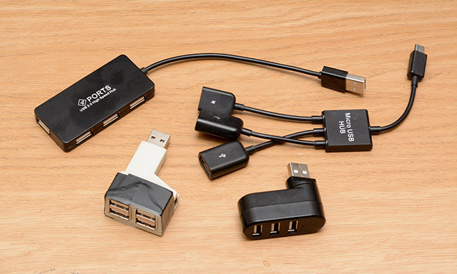
I started off buying a small usb hub because I was considering size to be an important factor. I found that it didn't work at all, all I got were USB enumeration errors. Looking at the circuit board, it just had an epoxy blob with no crystal, so I can only assume that it barely made the USB spec, and collapsed under the task of USB-OTG.
So I kept buying more hubs, and each of them failed to do the task in more and more ridiculous ways. I thought that perhaps it was a power issue, but even giving the devices external power didn't help. The USB enumeration errors give completely unhelpful error codes. Sometimes these codes were different, I'm not sure where I need to look to find out what any of them meant.
Not all of the hubs I tried failed with enumeration errors, some of them only supported USB 1.1, and some of them seemed to support USB 2 but did a kind of fallback onto USB 1.1 when plugged into the pi, or when the webcam was plugged into them. The webcam is particularly tricky because streaming video takes a fair bit of bandwidth, and one of the hubs appeared to be working fine, enumerated correctly and everything, but then mangled the video output of the camera. I wished I'd kept some of those mangled frames, mostly they looked like a correct image for the top third of the frame, then garbage for the rest of it.
The splitter-cable style hub in the picture above was even marketed as "for raspberry pi" but failed to function, I think it was one of the ones that fell back to USB1.1 when the webcam was plugged in. Inside the case, the board looked pretty similar to the other epoxy-blob hubs. Bizarrely there was an LED on the board which was completely enclosed by the case.
I suspect that all of these errors might have been to do with timing. There's a tolerance spec to the timing with any asynchronous serial data, but most devices probably function to a much tighter tolerance than that. If one device in the chain skimps on fitting a crystal, and operates mildly out-of time, the other devices can compensate. But assuming the webcam I got for £1.99 was also cutting corners, then the two devices in conjunction cannot function, even if they both technically are within tolerance. Just a theory.
I finally found a hub that worked, a rather large 7-port hub that has to be externally powered. Needless to say it was the most expensive of the hubs I tried, but less than all the money I'd wasted on the other hubs. This hub was far too big to fit inside the camera body. As with all 7-port hubs, internally it has two 4-port hubs with one plugged into the other. The chip itself is labelled FE1.1S, perhaps we could buy this chip in isolation? Or find a 4-port hub that uses it? Or desolder the chip from this hub and wire it up on protoboard?
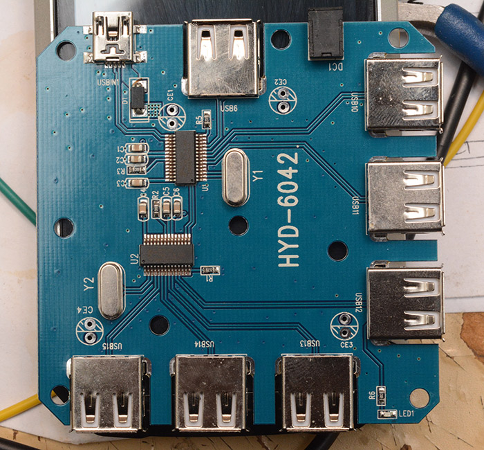
I continued to ponder this for some time.
The Reassembly and the Compromise
The Thermal Printer Instant Camera is a project that I'd worked on, on-and-off throughout October and November, in parallel with other projects. It kinda petered out and before I knew it, it was Christmas. It was, for reasons I won't go into, dreadfully important that the camera was finished by New Year's Eve, and suddenly I realized that I only had about four days left to finish. Although we had a plan, I hadn't started on any of the ATtiny power management stuff, or a driver for the autofocus motor. It was time to compromise.Instead of a self contained machine that boots on shutter depress, we could get away with a manual on/off switch, and during the 'on' time the Pi can monitor the shutter switch itself and shoot as needed. It does slightly belittle all our efforts to reduce the boot time, but they weren't in vain, because the lightweight nature of the image we've made uses less power and runs faster than the stock distribution.
With this cut-down plan, the main remaining tasks were to mechanically squeeze everything inside the case and glue all the software bits together.
Cut the USB
With time running out and no better option in mind, I broke out the cutting disks and surgically removed one of the USB hub circuits from the 7-port hub.
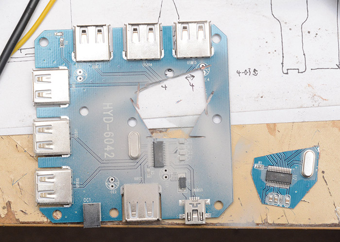
The circuit board is just two layers, so we can see exactly where the traces are and what goes where. Importantly we managed to hold on to the crystal, decoupling caps and pulldown resistors so the little chunk of circuit board should work in isolation. I tried to cut directly through the vias leaving continuity of the ground plane for both chips.
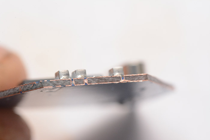
Although I hadn't planned for it, the remaining lump of circuit board does function perfectly well as a 3-port hub. I ended up using it in a different project a few weeks later.
The raspberry pi has lovely test pads on the board that make our life easier. USB OTG needs one pin to be grounded to put it into host mode, then the remaining four wires can be soldered straight to our new hub.
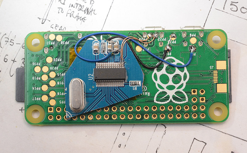
To this I then performed the rather fiddly job of soldering the differential pairs. I smothered the join in superglue after soldering to give it extra stability, it's exactly the kind of join that's likely to break as we're fitting the last part of the case back together.
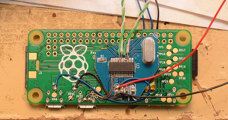
More Mechanical Mayhem
Given the short deadline, and the high-risk situation – if we cut too much of the plastic, there is no way to undo it, no way to get any replacements – I entered a kind of mechanical cutting trance, wielding only a mini-drill, cutting disks, razor blades, glue and of course the necessary eye and ear protection.A few hours later I had a huge pile of plastic shavings and the end looked almost in sight.
At some point I realized that the header pins for the flash attachment were exactly 0.1 inch pitch, and that I could use the FTDI adapter to connect directly to them when the case was closed.
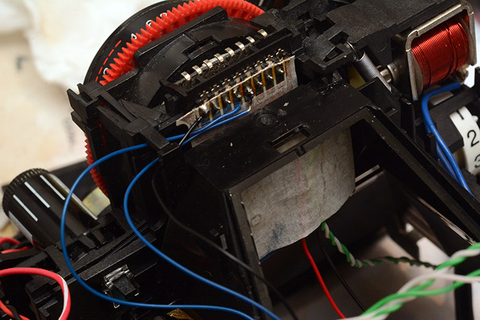
Visible in the picture above is the fitted webcam, with USB wires made intentionally too long. After fitting the pi to its permanent place, the wires were shortened by taking a section out of the middle, which is much easier than resoldering either end. Also visible is the solenoid for the shutter mechanism, which I've added wires to. Previously it was soldered to the flexible PCB.
I planned to re-use the battery and charging circuit of the thermal printer. This is a 7.4V lithium-ion which means we can just step-down to 5V from it. I didn't check if there was already a 5v step-down on the thermal printer board, it's probably 3.3v and even if there was 5v it wouldn't be rated for the power draw we need, to power the pi and the camera and everything.
I decided to fit a hard switch for the battery. It won't charge unless it's on, of course, but on the plus side we can turn everything off with one switch and not need to worry about standby power usage. I felt a little pang of guilt while attaching it, it seems unholy to be using a screw in a camera like this.

It's mounted at the front panel, behind the flap that's used for loading film cartridges. This seems the most logical place to fit extra controls.
Yet more cutting and gluing was involved in mounting the battery. It seemed logical to put it where the mirror had been, but that wasn't at all easy. And thinking ahead to where the roll of paper will go, suddenly things started to look very cramped indeed.

On the left is the pi, of course. Some of its GPIO pins have been wired up to the shutter switches. I reused the original terminals to the 6v battery as power terminals here, and between them is a small step-down module set to 5.1V. It's always on, except when the battery switch is shut off. Had we not been in such a hurry, something more desirable might have been possible. On the right we have a circuit used for triggering the shutter solenoid.
This circuit was hastily thrown together and didn't work properly, but went something like this:

A high-side switching mosfet that lets the low-voltage output pin on the pi short the full battery voltage across the solenoid. There's a huge cap, and a low-value resistor. The idea was that I could adjust the value of this resistor (labelled 100R above) so that there was just enough energy in the cap to fire the solenoid, but not enough to hold it open, so it would spring back. I think I made a couple of mistakes in this circuit, there probably should have been a protection diode, there probably didn't need to be current limiting on the mosfet gate, and I might have damaged the mosfet by wiring it up wrong to begin with.
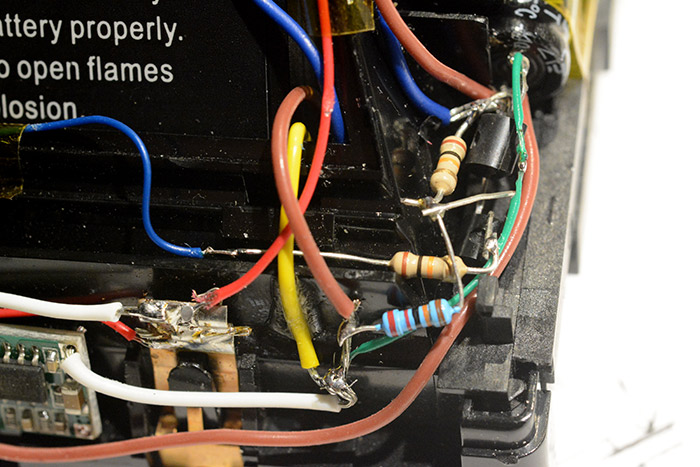
Still, it functioned enough to get a click, if not as good a click as when the battery was shorted directly to the solenoid.
The GPIO abstraction on the Pi, WiringPi, is excellent. It's everything an abstraction library should be, no fuss, just set this pin as an output and make it high or low. Compare to the abstraction layers on the STM32 series of chips, where you need register-level knowledge to get anything to work, thus defeating the point of an abstraction layer entirely.
More importantly, the WiringPi package comes with a binary so we can easily work it into our shell scripts. One very useful feature is wfi (wait for interrupt) to wait for a rising or falling edge by blocking execution. I wired both the half-depress and the full-depress to the pi's GPIO, even if we only end up using one of them.
Prepping the printer
The print head is removable from the board, attaching by a ribbon that goes into an FPC connector. I'd been trying out various orientations for it throughout the cutting and gluing phases, but not with the main board hanging off of it. The ribbon isn't exactly long, and the orientation to get the print-head as close to the front as possible means that the ribbon will be forced to fold back on itself. We could sacrifice position, moving the print head further away, but that would either mean big gaps between pictures, or not being able to see the picture until a few more have been taken. Neither option is attractive. The circuit board can just about fit underneath the print head, where the cartridge would have sat, but in addition we need to feed the paper through there so it's a very tight fit. The paper roll can just about go into the main cavity next to the battery, but with the orientation (the paper can only be printed on one side) the roll needs to be mounted backwards, with the paper doubling-back on itself. Not ideal.There's more. The printer has a daughterboard with the controls and lights on it. I was doing this on the morning of New Year's Eve, with the deadline looming, and the compromises were starting to get heavier. There's only one absolutely essential component on the daughterboard, the soft-power switch. With further experimentation I could have potentially tricked the printer to powering up when the battery is connected, but I didn't have time for that now. All that's needed is a resistor and a push switch. The LEDs aren't needed, and the feed switch would have been useful but isn't critical to have.
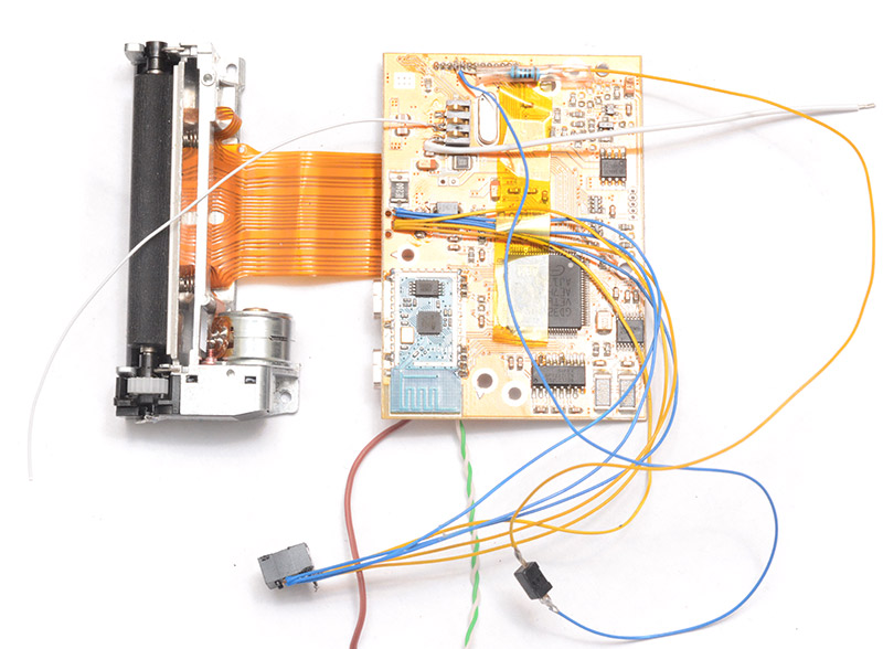
The battery terminals were extended, of course, and the charging barreljack was desoldered and put onto flying wires (I doubled up the thin gauge wire for flexibility without compromising the charge current). The thermistor lead to the battery was soldered directly once the board was roughly in place, it isn't cut when the battery is disconnected, but it shouldn't matter.
Compromises, compromises... the soft power switch was stuck next to the hard one. Not at all pretty, but at least they're covered up when the flap is closed.
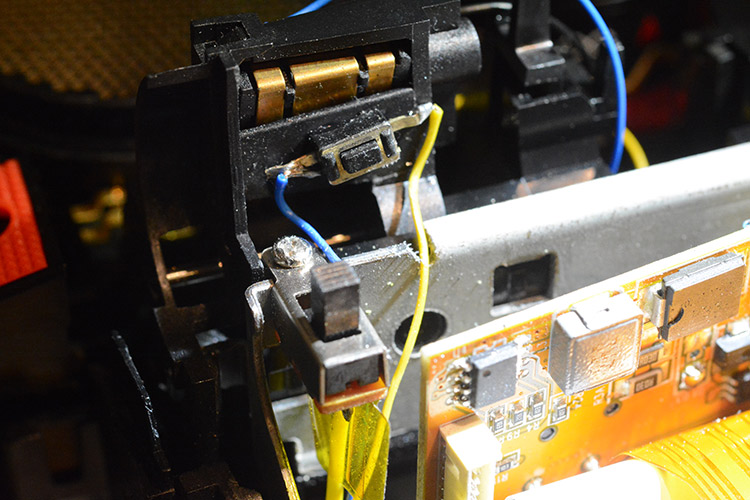
This also gives an idea of where the printer board has to sit, just because that ribbon is so short. Life would have been made easier if I'd ripped out the autofocus mechanism, but even with all the compromises I couldn't bare to do that – deep down, some part of me assumed I'd come back to this and finish that bit.
Making room for the printer meant gutting everything in that front mechanism. I'm not sure if I got the point across yet about how much cutting and drilling this project involved.
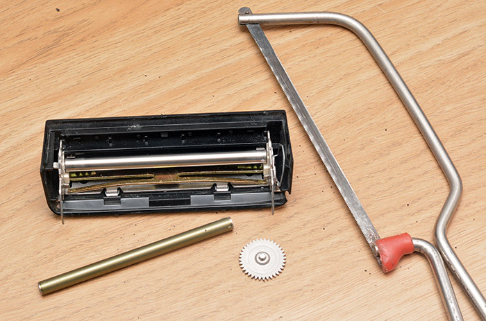
That's after sawing through the bearings on one of the rollers. There's a spring-steel lever that applies a lot of pressure between them, and the metal gear is driven by the mechanism on the main unit that we ripped out earlier. I removed all of the metal, then a lot of the plastic, then some more plastic, and then some more plastic again.
It was about 7pm when I finally got the whole thing closed up and apparently intact. I didn't have time to test it. I just chucked everything in my bag and headed out.
Get your shebangs right
Although everything should have been dandy, I hadn't actually done one of the most crucial bits, that is, tie everything together with bash scripts.So, coolest kid on the block, I arrived at the New Year's Eve party with a serial cable and a laptop in order to finish programming my camera.
Lucky I'd stuck that serial port on the outside, eh?

Above is a re-enactment of how the serial cable attaches. Pretty neat, or at least it would have been had I not subsequently needed to dismantle the camera anyway. The mosfet for the solenoid had been wired up incorrectly, and I soon noticed the side of the camera was getting worryingly hot. I had to pull the thing apart, and cut the wire to the mosfet, thus (temporarily) breaking the shutter solenoid action, but giving us a working camera.
BusyBox is not bash. It might behave a bit like it, but it's actually ash, and one crucial point to look out for is to get your shebangs right. In my haste I'd automatically started writing my bash script with the line #!/bin/bash when it should have been the more generic #!/bin/sh. Confused and in a rush, I didn't spot that but I did note that you can invoke a script manually by typing ash shoot.sh. In that case, it doesn't need a shebang at all, and it doesn't even need the executable flag set.
We'd condensed everything individually into convenient scripts, so all that was left was to construct an infinite loop that listened for the shutter press and ran our scripts. It looked something like this:
while true; do

  gpio wfi 27 rising

  ash shoot.sh
  ash print.sh

done
The jpeg image is passed between the two scripts by being stored as /tmp/output.jpg. In /etc/fstab, /tmp/ is mounted as a ramdisk / tmpfs so this should be very quick, and should also prolong the life of the SD card.
At last, we were able to take some pictures. Or were we? Disaster as the paper almost immediately jammed on one side. Turns out I hadn't cut enough plastic away, and the print head was not horizontally aligned with the paper, causing it to crumple up on one side.
Not to despair, I did the only sane thing any sane person would have done in an insane situation like that: I taped the print head in place using duct tape. And it worked!
Guests at the party were not particularly unnerved by the presence of duct tape on an otherwise marvellous instant camera.
Here are some shots from the event, taken on a phone camera shortly after several metres of pictures were taped to the walls.
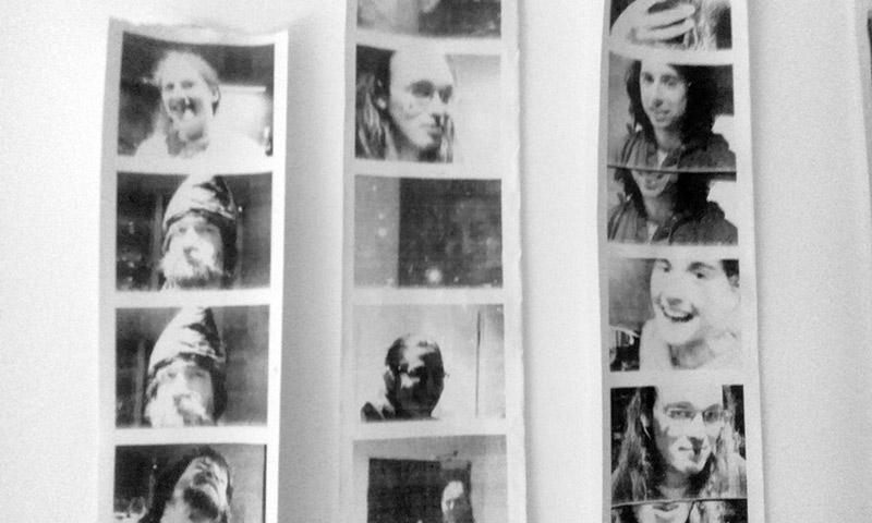
On the left, yours truly wearing some traditionally ridiculous headgear. Couple of paper jams are obvious on the right hand side.
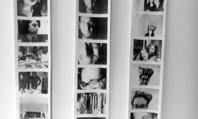
A few interesting closeups, and yes, it's a tea cosy. Shaped like a chicken tabby cat. We did find that the viewfinder in the camera didn't quite line up with where the webcam was pointing, it would be helpful if the print-area was circumscribed onto it.
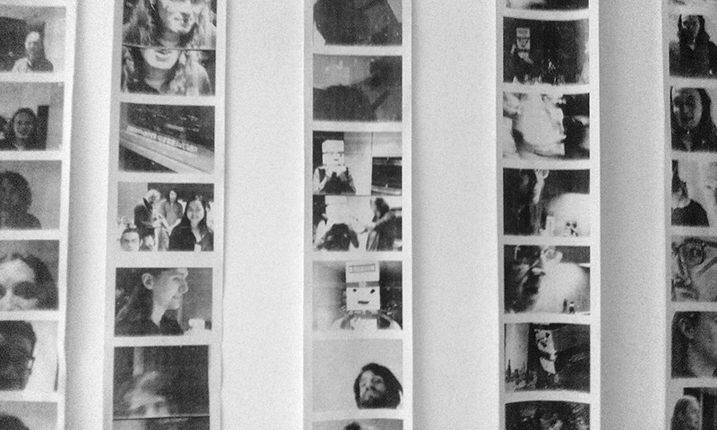
And there's a man with a box on his head. His identity shall remain unknown. In the middle-left of the frame there's a picture of my GPS Precision Clock which I'd also taken with me to the event, it's an excellent prop when countdowns are involved.
Ah, but folks, it's not over yet! The camera performed perfectly, but there's still the matter of a few important final touches.
Automation
We compromised in many ways, but there's one compromise we can't get away with. In order to use the camera on New Year's Eve I had to start it up and then run our script using the serial terminal. A finished camera needs our software to start automatically.
This sounds super easy, but I was especially cautious about messing this up. I'm editing the init scripts using the serial port, but if we bugger up the boot process we have to completely disassemble the camera in order to access the SD card and fix the problem. I was already aware that the scripts in /etc/init.d/ are blocking, that is, the init process waits for them to finish before continuing. Our script is an endless while loop, waiting for button presses, so that won't work.
I was informed by Tom that the correct place to invoke our script is in /etc/inittab. BusyBox handles inittab a little differently to normal, not only are some features not supported but it will even work without the inittab file at all as it has built-in defaults. The mistake I made was that I copied the line that invoked /etc/init.d/rcS, that is, the action is specified as "sysinit", which means that I ended up invoking it in a way that waited for it to terminate after all.
Not only that, but I'd been extra cautious, and instead of an endless while loop, I'd stuck a count to 100 before exiting. Only, the way I incremented the variable was with the ((var++)) syntax, which isn't supported in ash!
My own stupidity then is the only thing we can blame here for needing to dismantle the camera yet again. It's possible to solve the sysinit problem by simply forking another process to the background, but the correct action to set is "respawn", the same action that's used for starting the terminals.
Worse still is that during re-assembly, I damaged one of the wires and broke the USB enumeration for the webcam. Oh how my heart sank as I witnessed the enumeration error -32 yet again, I thought I'd seen the last of it. Another dismantling and I located the fault (it was where I had joined the differential pair in the middle, not at either end) and reassembled it for hopefully the last time now.
Or at least, the last time until we have to restock the paper roll. It's too big to fit in through the front flap, so the only way to reload it at the moment is to pull the front fascia off. Thankfully there's at least three or four hundred pictures per roll. Back before I started compromising everywhere, I had planned to cut an opening in the bottom to facilitate easier reloading, but in the end it probably wouldn't have been all that useful. As I mention in the video, the best idea would be to allow a whole roll to be sucked in via a motorized reel, but this would come with a whole extra pile of engineering problems. Hmm, reinventing the reel – maybe next time.
More final touches
Long before the final assembly I'd wired the little LED under the viewfinder to one of the pi's GPIO. I'm not sure what it originally represented, as it's quite unpleasant to have an LED directly in your eye. To be fair, the original LED from the 70s was exceptionally dim, and maybe I was mistaken when I replaced it with a modern equivalent. The best use of this was probably an indicator that everything is ready to go. I set the LED output on when our initialization takes place, then once both/dev/video0 and /dev/usb/lp0 have appeared, the LED turns off and the main script begins.I mentioned that the solenoid didn't work on New Year's Eve, so after fixing the wiring mistake I was able to implement this too. Instead of clicking on and off through hardware, it was easier to just momentarily pulse the pin controlling it.
#!/bin/sh

gpio write 1 1
sleep 0.05
gpio write 1 0
This script can then be invoked with a trailing ampersand, which forks it to the background. Even if the sleep was for several seconds, it wouldn't delay the processing of the image after the picture's taken.
And of course the last big fix that's left was the mechanical mounting of the print head. It only needed to be moved over about 3mm, but that required a whole extra afternoon of gentle plasticwork. In the end, everything fit together nicely. The following pictures have the flap open to demonstrate how close the print head is to the front, and how little material of the front flap remains.
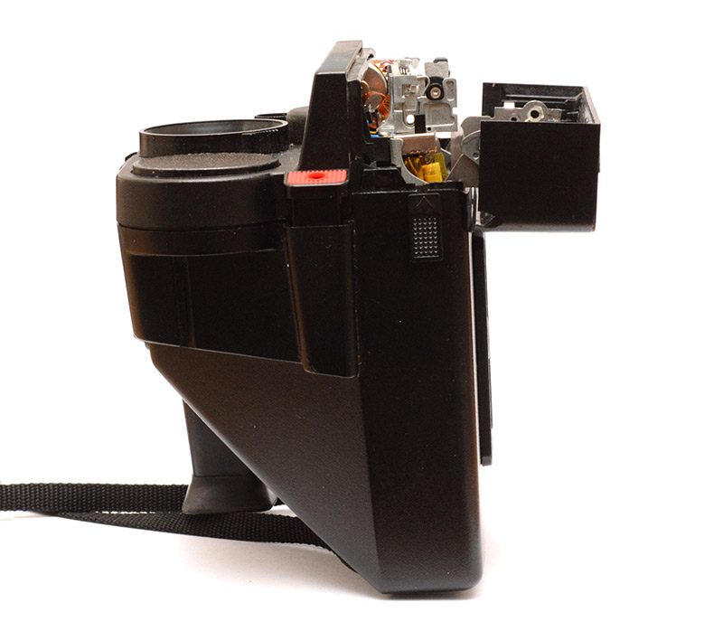
The photo below shows the arrangement and how the ribbon to the print head has to fold back on itself. The barrel jack for charging is glued to the print head on the right hand side.
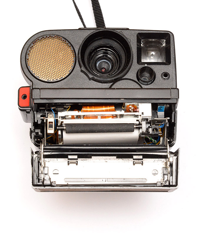
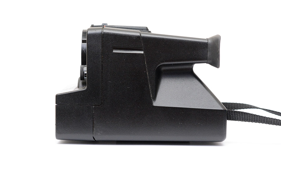
With the flap closed, you wouldn't know this was modified at all, except for the missing front element, and the fact it prints onto paper.
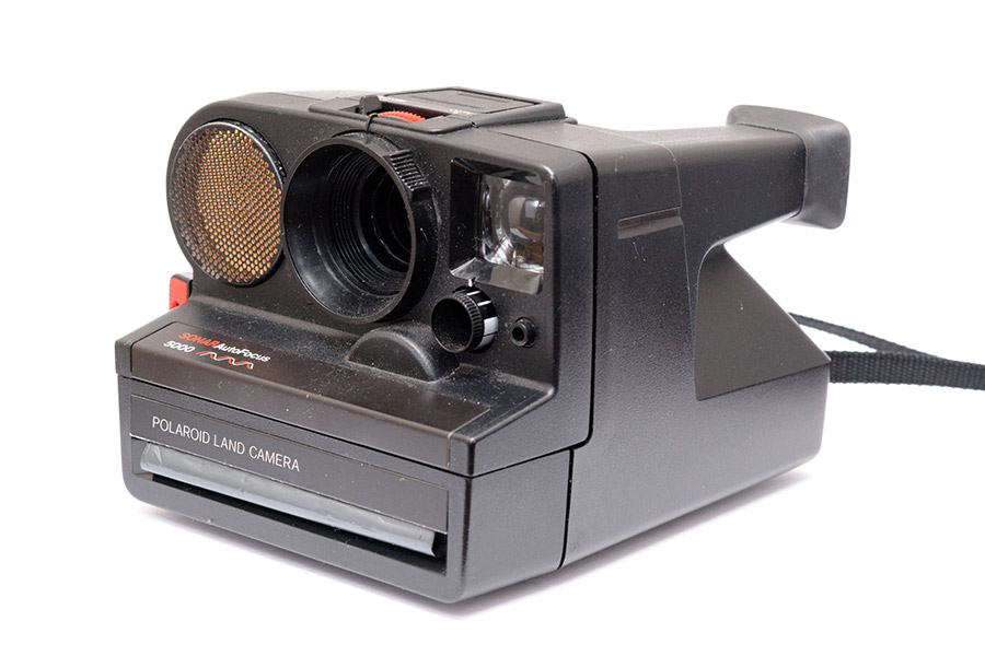
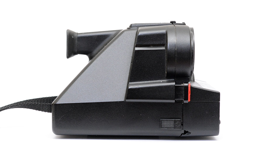
The corner of the flap there was damaged when I bought the camera, and remains as the only bit of exterior plastic to show any damage.
Our final shell script looked a bit like this.
#!/bin/sh

gpio mode 27 in # Shutter button half press
gpio mode 27 up
gpio mode 25 in # Shutter button full press
gpio mode 25 up

gpio mode 1 out # Shutter solenoid mosfet
gpio write 1 0

gpio mode 4 out # Viewfinder LED
gpio write 4 1

while [ ! -e /dev/video0 ] ; do sleep 0.1; done
while [ ! -e /dev/usb/lp0 ] ; do sleep 0.1; done

gpio write 4 0

while true; do

  gpio wfi 27 rising

  v4l2-ctl --set-fmt-video=width=640,height=480,pixelformat=0 --device=/dev/video0
  v4l2-ctl --stream-mmap=1 --stream-count=1 --stream-to=/tmp/somefile.bin --device=/dev/video0
  /root/yuyvArm /tmp/somefile.bin /tmp/output.jpg

  python ep2.py /tmp/output.jpg >/dev/usb/lp0
  echo " ">/dev/usb/lp0

done