
StyloCard
5 May 2018Progress: Complete
Printed Circuit Boards as a business card are a great gimmick. I'd seen ones with USB ports etched into them, which enumerate as a keyboard and then type a person's name or load up their website. It's just about possible to build them cheap enough to hand out as a business card, at least if you're picky about who you give them to.
A couple of years ago I took a stab at making one for myself, but I didn't want it to be pointless. I wanted it to do something useful! Or at least entertain someone for longer than a few seconds. I can't remember quite how I got the idea of making a MIDI-stylophone, but the idea was perfect. A working midi controller, that's unique enough in its playing characteristic to potentially give some value, while at the same time costing no more than the card would have done otherwise, since the keyboard is just a plated area on the PCB, as is true on the original stylophone.
To have the full range of 20 notes without using anything more than the ATtiny85, there's only one real way of reading the keyboard, and that's using the analog-to-digital converter with a resistor ladder along the keyboard. I took lots of inspiration from this excellent MIDI stylophone project including the very sensible idea of splitting the keyboard into two sections that are read on separate analog channels, to halve the required accuracy in the resistor arrangements.
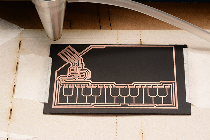
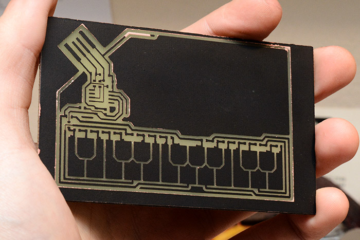
I have the pictures from when I home-etched my first prototype, which involved my usual process at the time: spray paint, laser-etch...
...and soak in ferric chloride.
There was an extra step this time, though. I tried to tin-plate the keyboard part in order to form a durable layer that would resist oxidation (and of course to get the silver effect true to the stylophone design). I had a fair bit of trouble getting the tin plating to work, I can't really remember the details though. Certainly having a clean copper surface first is essential.
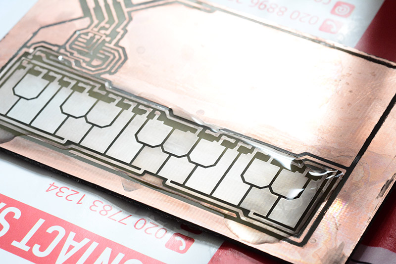
In the photo above I'd dribbled some of the plating solution onto the keyboard area, and it did have an effect, but seemed to resemble more of a matt grey than silver.
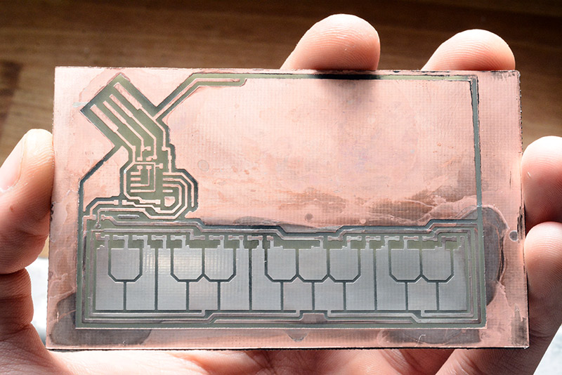
I expect it would require multiple applications to get a nice thick layer of tin. However I remember that I was keen to see if the keyboard worked, so I proceeded to populate the parts.
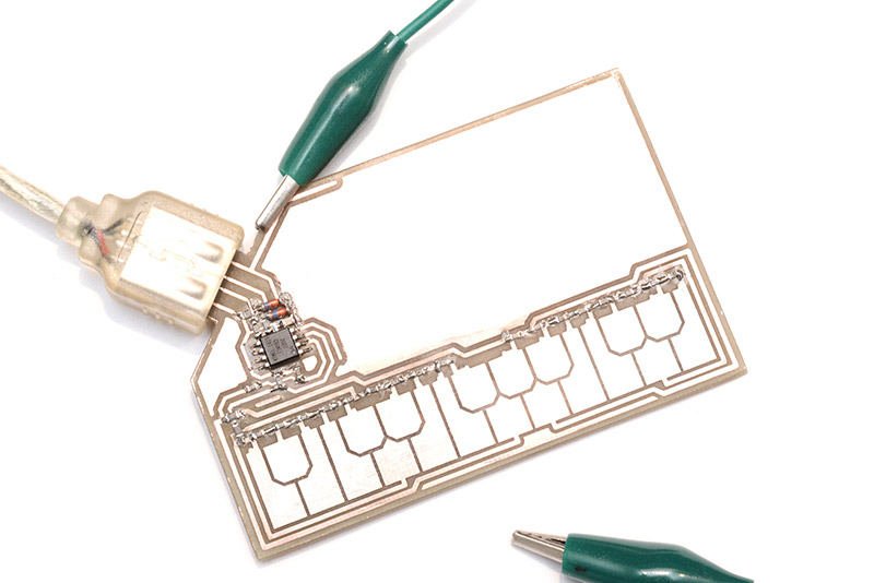
And work it certainly did! I used a crocodile clip as the stylus since I hadn't come up with any better ideas at that point.
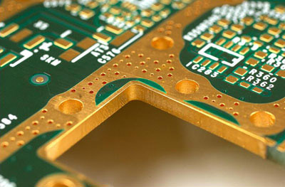
The next step was obviously to order a bunch of boards of this design from some cheap chinese manufacturer, but before doing that I wanted to work out how the stylus could be improved. My main idea was to have a rectangle of the PCB in the shape of a stylus, and using the same process that's used to produce castellated boards, edge-plate the tip. It's possible to have this done, normally for RF shielding purposes, as this stock image shows:
In my design, the tip of the thin rectangle would be coated, and the other end would have a pad where a wire could be soldered to it, joining the stylus to the main board. The stylus could be snapped off the main board when the user first uses it, and would hang from the wire, or maybe even have a routed slot that it could then snap in to.
But edge plating is expensive, and it means a PCB that's meant to be cheap enough to hand out to people becomes ten times as expensive, and somewhat defeats the point.
Then I thought about finding a nail, or a pogo pin, or something that could be attached to the PCB stylus as a component, or perhaps used as a stylus on its own. By making a routed slot in the centre of the board (where the stylus holder goes on an ordinary stylophone) we could have a place to clip a stylus in, possibly with some kind of spring design in the shape of the routed board.
I continued to ponder about this for months, and then eventually forgot about the whole project.
Fast forward to two weeks ago, when I remembered this endeavour, and I decided that although I still hadn't come up with a stylus solution, I probably wasn't ever going to at this rate, and maybe I should just order the board as I had designed it back then. So I did!
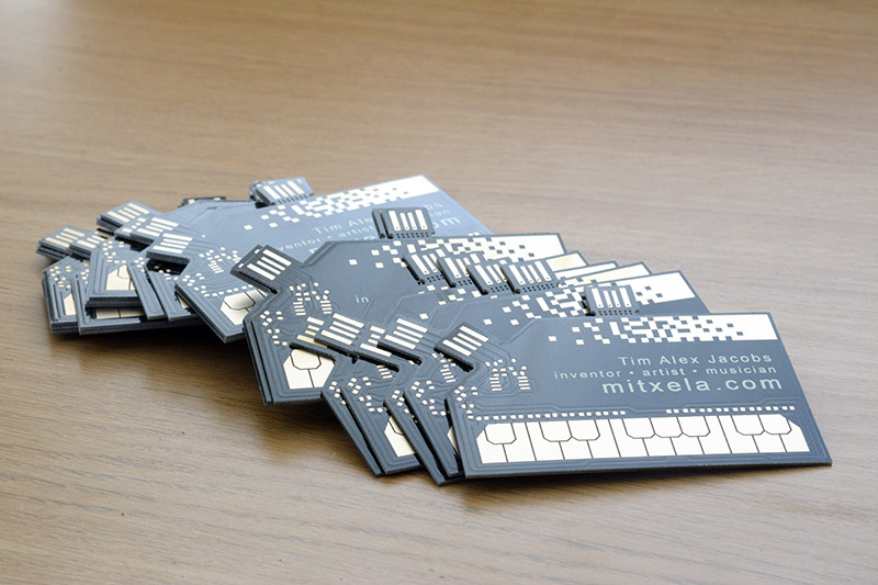
Including postage (which was about a third of the total cost) the boards ended up about $3 each. I paid extra for the immersion gold finish, because HASL (where it's dipped in solder and blown clean) does not look pretty at all.
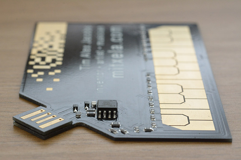
The extra USB port at the top is my solution to the thickness problem. Making the whole board thick enough to make contact in the USB port would be ugly, so I chose a thickness of exactly 1.0mm, and then that extra part can be snapped off, and soldered in place along with the rest of the components, like they do with castellated boards. This means the USB port makes a good connection and the card stays thin.
The total thing is the same size as a standard business card, of course, fitting into an 85mm by 55mm rectangle. The keyboard is 78mm wide, compared to the 120mm of an original stylophone.
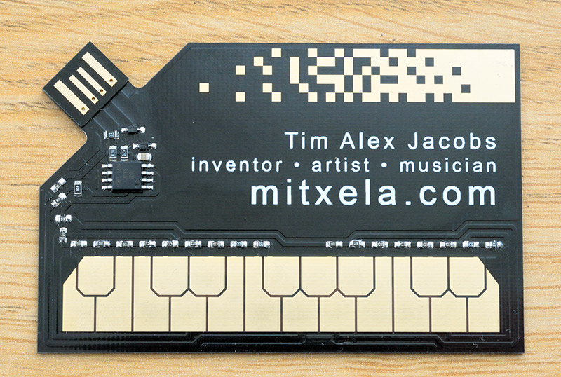
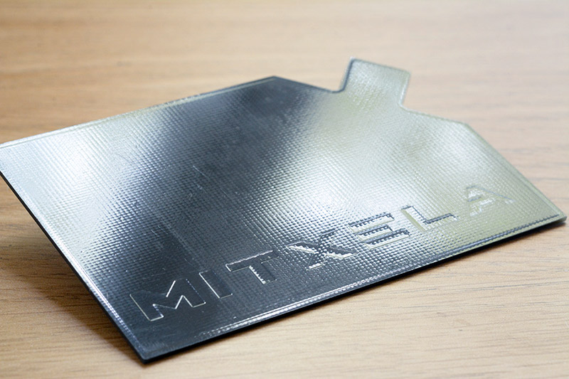
Since the board was laid out as a single layer, but the USB rectangle needed two layers, the whole thing was ordered as two layers (the cost difference is less than 5%). With nothing else needed on the bottom layer, I chose to etch my logo into it, then cover the whole thing in black soldermask to make it appear as a subtle embossed pattern.
When it comes to business cards, the entire point is to show off.
One big improvement would be if I'd moved to a QFN part, which would reduce the amount that the main chip sticks out. But a QFN ATtiny would mean adding a programming header, since you can't get a test clip for a soldered-down QFN part. Better still would be to move to a part like the ATmega8u2, which is one of the smallest and cheapest parts which has a hardware USB port. Not only that, but it'd have enough pins to directly read the keyboard without needing so many resistors. That could potentially be worth the hassle, since it'd reduce the part count so much, and hence shorten the assembly time, which really is the biggest cost.