
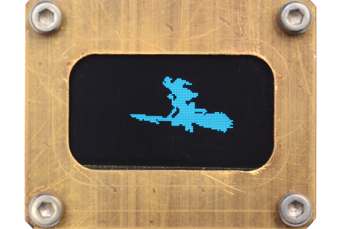
Steampunk DDC OLED
12 May 2022Progress: Complete
Gosh. It has not escaped my attention that my rather stupid project received a rather stupid amount of publicity. It's unlikely I will ever beat that ratio of effort to internet points.
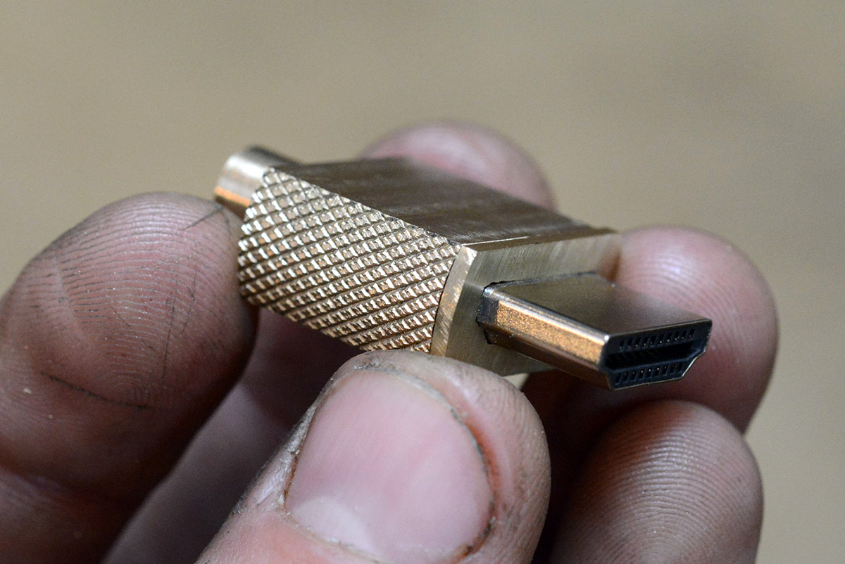
Stupid, silly, pointless – it seems these are my buzzwords. And what's a sillier upgrade for the silliest display than making it steampunk? But I never went in for sticking golden spray-painted gears on my hat. When I talk steampunk, I talk milled brass and knurling.
Check out this video for the making-of and demonstration:
As usual, the musical accompaniment is an original composition, and is available in high quality on my bandcamp page.
The Build
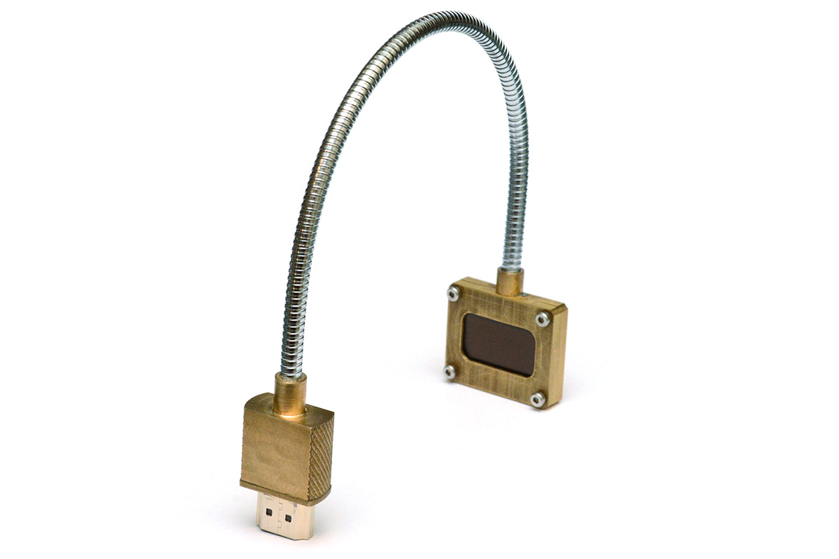
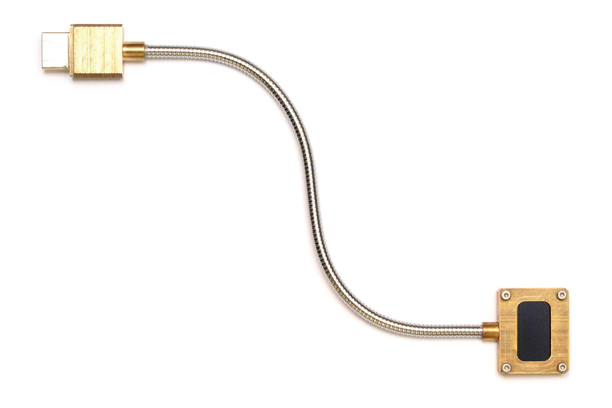
With the exception of the USB Light, from which I salvaged the bendy gooseneck thing, all of the parts were sourced from bits I had lying around. It is extremely satisfying to go from initial idea (of "bendy gooseneck milled brass HDMI DDC display") to finished prototype the following day.I first threw together some very quick OpenSCAD drawings, just to keep track of dimensions, and later, to test whether a chamfer would look good. The chamfer is a clunky cube subtraction since I don't think OpenSCAD has anything else suitable, but starting over in a "real" CAD package would take longer than copy-paste.
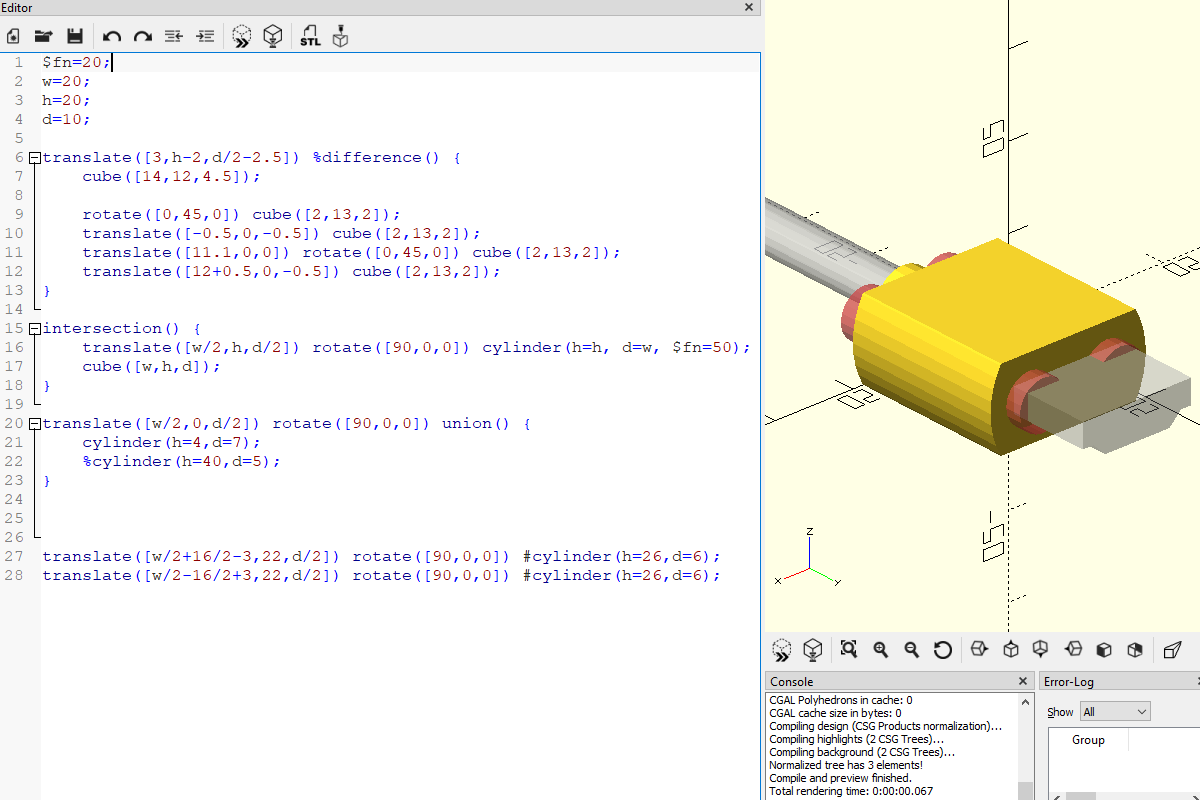
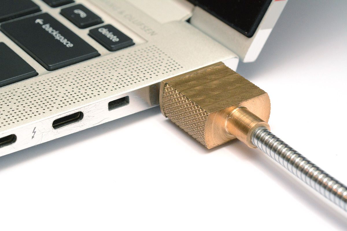
For the connector the only things I cared about were what overall diameter the knurl should be, and whether the 6mm endmill slot would be sufficient. The red marked cylinders highlight the endpoints of the slot.
There may have been a clever way to assemble the connector, maybe using tiny bolts and threaded holes, but I decided to go with a single join that is hot-glued in place because it was the funniest option.
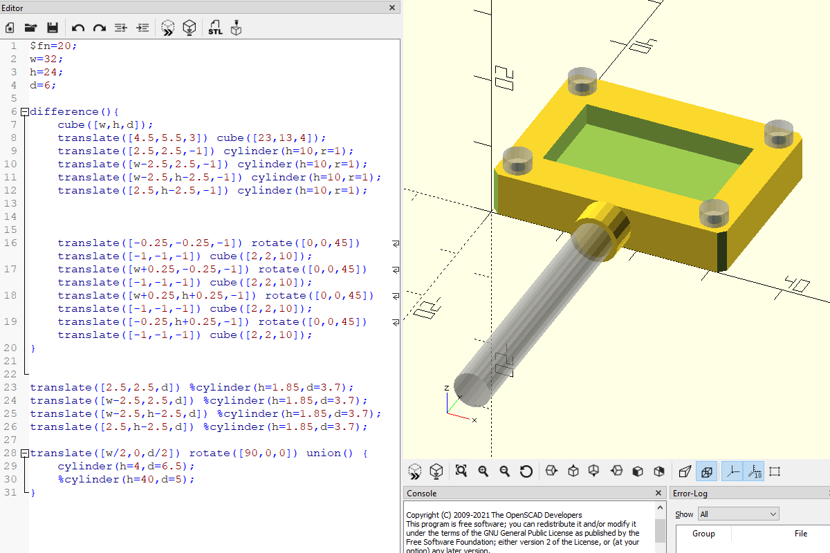
I'd originally planned to use much smaller bolts to hold the display together. My tiny tap-and-die set goes all the way to M1.0, but I didn't have any appropriate bolts to fill those holes. I had some M1.6 bolts but they were too short to join the display together (unless perhaps I added a deep countersink, which didn't look great when I tried it in OpenSCAD) so I went with the M2 bolts.
The reason for the (possibly confusing) "patina" shot in the video is because after soldering the display side together, it was visibly a different colour to the freshly cut connector. After a while, I expect it all to fade to the same dull brassy colour, but to accelerate the process I hit it with the blowtorch again.
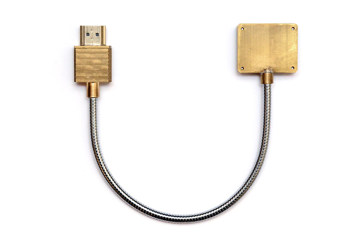
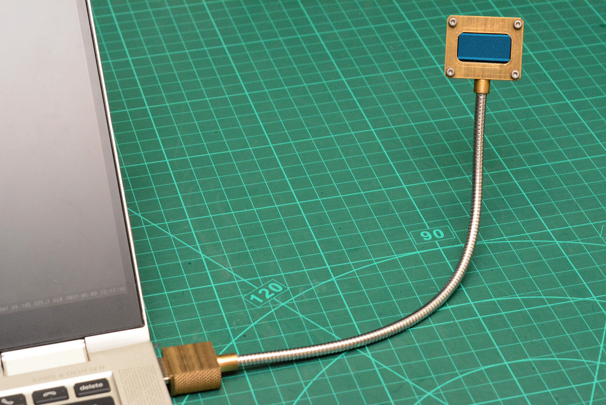
I spent a good while trying to decide what length of bendy gooseneck thing to use. I was very tempted to go for the shortest possible amount, as shown in this early mockup:
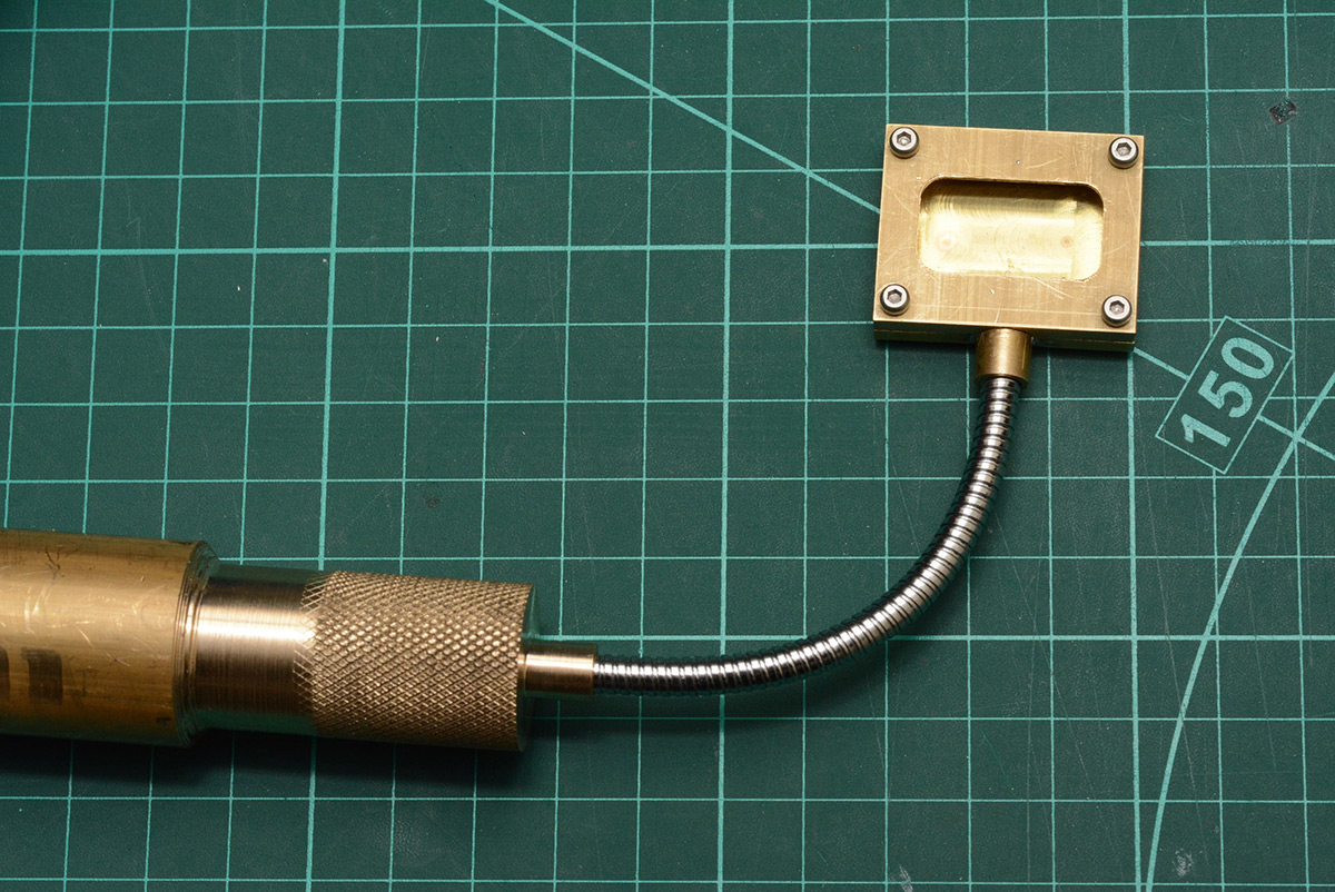
That gave just enough room to bend it 90 degrees, which is kind of funny and adds to the pointlessness of it all. But I ended up making it a bit longer, to allow pointing it in most directions. Remember that the bendy gooseneck thing is glued in at each end, not freely rotating, so a shorter bendy gooseneck thing also limits how much you can twist the display on its axis.
The great thing about "steampunk" is that you don't have to clean your solder joints. The messy flux residue just adds to the look.
Bendy gooseneck thing!
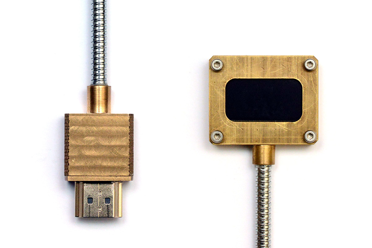
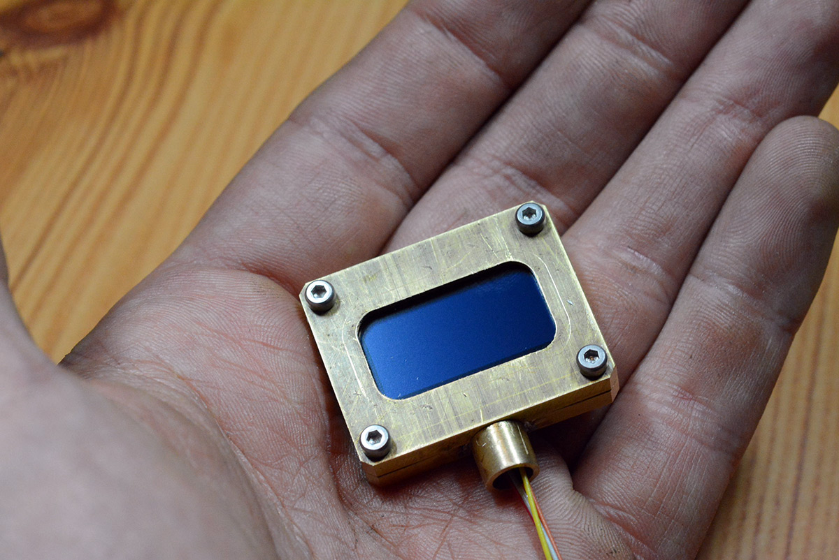
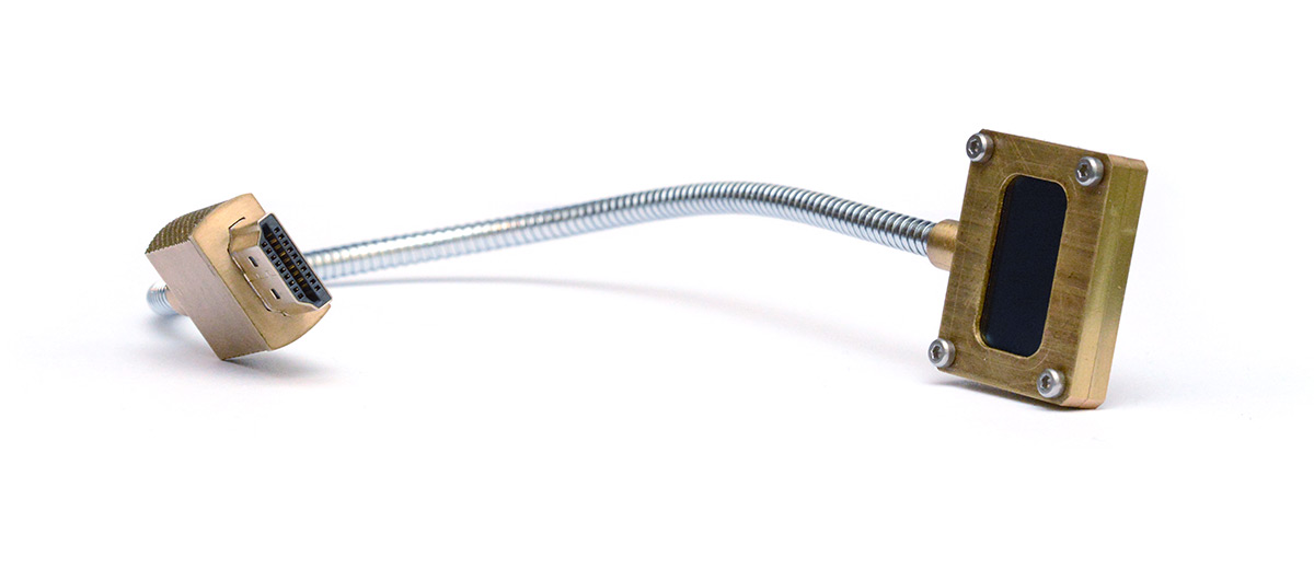
You may notice in the demo shots that the display isn't quite centred within the bezel. I was being really careful not to crush the delicate glass panel, so I left about half a millimetre of slack all round. As a result, the screen can slip a little as you manipulate the display. It's less obvious in real life, but the macro lens really draws attention to it. I may fix this by opening it up again, and adding some double sided tape or padding around the edges.
Driver improvements
If you're still reading, it's probably because you're craving something a little more intellectual. After all, metalworking is for dumb-dumbs, right?*
I should first mention evdi which was pointed out to me shortly after posting the DDC OLED. I haven't tried it, but it looks exactly like what I was searching for to begin with, a virtual display interface for precisely this kind of application.
My laptop's DDC port is running at 100kHz. That's about 10kBps if you include the start and stop bits, and given it takes 1kB to fully update the display, our theoretical maximum framerate is about 10FPS. With the overhead of the single-threaded python script it's less than that, since the writes are blocking and the image capture/bit shuffling takes some time. Obviously the display can render much faster than this. Even forgetting the parallel interface to the SSD1306, in a different scenario we could run the i2c at 400kHz. But with DDC, there ain't much we can do.
Instead, let's do that thing I said I wasn't going to do, and upgrade our script to only transmit differences.
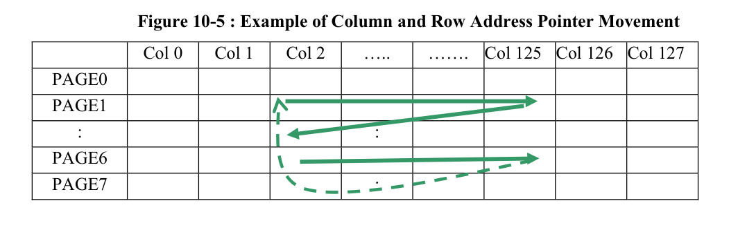
This shouldn't be difficult, except for all the quirks of the SSD1306 that get in our way. Following the bit-shuffling, we stream a full kilobyte of data for each frame. The controller is configured so that when it reaches the end of the row, it continues from the next. Unfortunately, there's no easy way to position the pointer. If we want to skip the first N bytes, we have to reconfigure the draw area. Doing so means that when we reach the end of the row, the next one will begin at the first column of the draw area, not continue from the first column of the display. When you change the draw area, the pointer is always reset to the top left corner of that rectangle.
The overhead in reconfiguring the draw area is something like eight bytes in total, because unless the next row needs to start at exactly the same column, we'll need to reconfigure the draw area again when we hit the page boundary. It's also important to keep in mind that if the entire frame needs redrawing, we don't want that to take any longer than with the original driver.
I got this to work OK. It could certainly be optimised. Specifically, if only a small rectangle of the image has changed, we should be able to detect that, and only send one draw-area-reconfigure command. Even if the first column is not identical for each changed row, if they're within a few bytes of each other, we'd save overall if we can slap a rectangle around the area, and just stream data for there. Unfortunately, this means slicing up our original data in a way that quickly gets confusing. If there were two small rectangles of changes on the display, we'd need to transmit bytes out-of-order.
Instead, I went for the simple option of "If the next N bytes are unchanged, and N is greater than the cost of reconfiguring twice, skip them."
Note that with dithering enabled, this alone doesn't provide much of a speedup. Python's image .convert(1) has the choice between Floyd-Steinberg dithering, or no dithering at all. With dithering, anything to the lower right of any change will probably also change, as the dithering pattern is disrupted. A more primitive dithering algorithm would be much more effective, but better still is to apply the dithering before drawing the mouse cursor. This at least means that when you move the mouse, it's responsive and the rest of the screen stays still, instead of pulsating with the dither variations.
The other improvement I've made to the repo is to add a wrapper script, both to detect the i2c device by name, instead of the volatile device number, and to automatically perform the xrandr setup and teardown.
That sums it up for this project. The raw video footage was about three and a half hours. Editing it down to under twenty minutes took significantly longer than that.
* False. Only dumb-dumbs believe that metalworking is for dumb-dumbs.