
Stainless Infinity Cube
8 Nov 2025Progress: Complete
With the re-opening of the London Hackspace, I once again have access to a milling machine and a big lathe. I loudly lamented its closure, so now that it's back (in unfortunately much smaller premises) I have a duty to start doing silly metalworking projects again.
The Brass Infinity Cube is great, in fact over time it got a little better because my original complaint, that it was too heavy, went away as my hand muscles got stronger. The only real downside to the thing is the brass gets a mucky residue if you play with it long enough. I'm not sure if it's sweat reacting with it, or something else, but it means that after fiddling you need to wash your hands. Making it out of solid stainless steel should solve this.
Brass is famously easy to work with, steel is more difficult, but stainless steel is on another level. Even the mildest grades of stainless are notorious for being difficult to machine. Along with being a lot tougher, it has a tendency to work-harden if you get the feed wrong, so if, say, you drill a hole too slowly, the friction turns the bottom of the hole into a glassy layer that's almost impossible to drill further. Anyway I'm sure we won't have any problems.
Squaring up
I started with this chunk of 304 stainless that I'd bought right after I made the brass version. Nominally 20mm square profile, it has some mill scale or texture that we need to machine away.

The fly cutter seemed like a fun way to clean it up. The side-to-side tram on the mill doesn't seem too bad, the rear pass makes the lightest spring cut, as my cutting fluid evaporates.
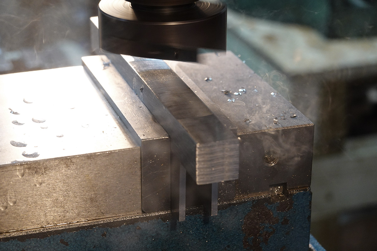
Of course, the side-to-side tram doesn't really matter, what matters as we try to square up the stock is the forwards-backwards tram, or nod. With the first surface as a reference against the jaw, we clean up the next surface and should end up with them perpendicular.
I quickly chucked an indicator on the head, and measured about 6 microns of nod over a swing of about 10cm. That's pretty good, it's hard to dial a bridgeport in better than that. I ploughed ahead.

However, pressing it against a V-block and silhouetting it against the light, it clearly was less square than I'd planned. Turns out I'd mis-read the graduations on the indicator: it was actually out by 60 microns over 10cm. Blast.
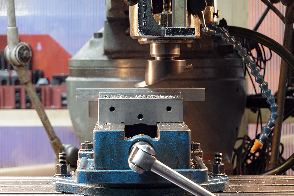
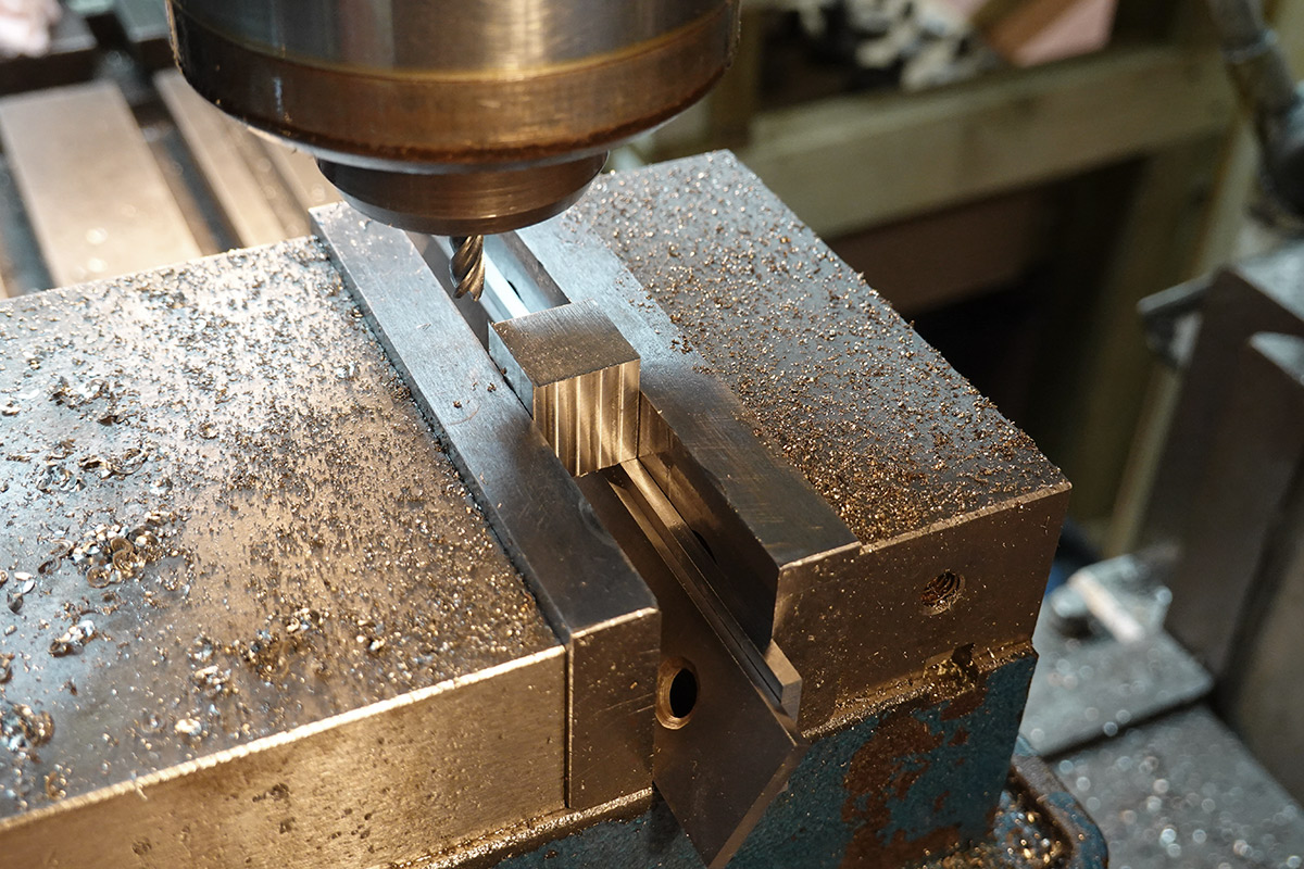
I don't think it really matters, but we might as well get them squarer than that. The easiest way is to machine the surfaces again, in several passes with a small endmill.
This could take a while. Thank goodness for power feed!
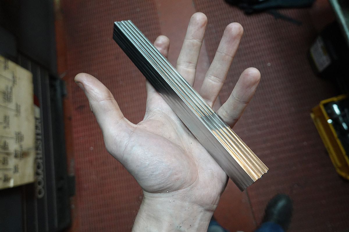
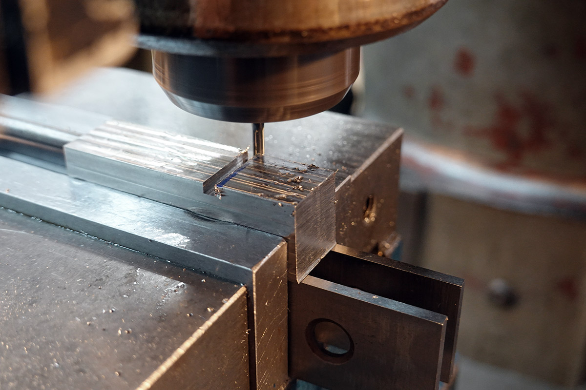
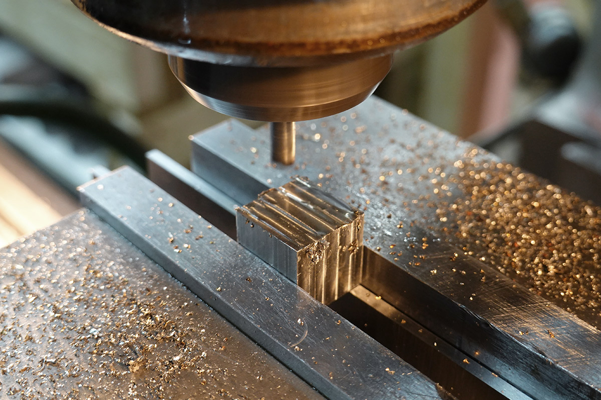
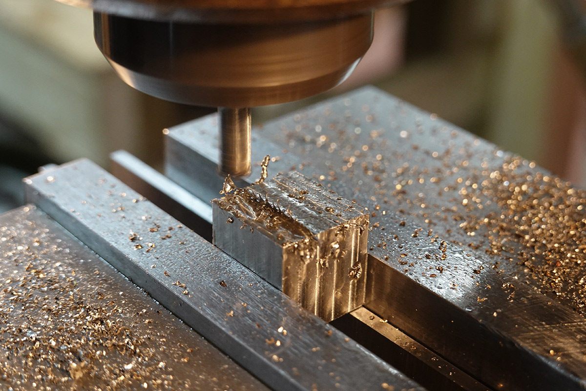
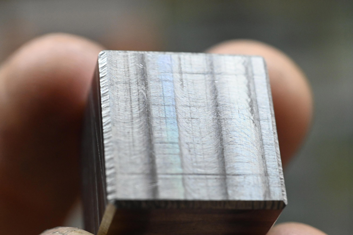
The process leaves quite a nice polished surface. It's flat to the touch, but reflects light in a dazzling pattern.

After much machining, we ended up with an actually square bar. I kept one fly-cut surface, because it didn't strictly need to be re-cut. I may regret that later, but I was starting to get bored.
The bar ended up as a 19.5mm square. When I originally planned to build this, I'd ordered some smaller stock as I wanted to scale it down, maybe a three-quarters size infinity cube would work better in terms of weight. Then I changed my mind, and wanted to build it one-to-one, where the original was made from 19mm stock. Here in this process of whittling down the stainless, two hours in and all we have is a square bar, I reached the 19.5mm number and decided that was a great size to make it.
Next up, as before, we need to saw off oversized cubes, machine a reference surface onto each one, square up the other end, and then mill down the initial surface to dimension.
I used the donkey saw (power hacksaw) to chug through this – the hackspace doesn't have a proper metal bandsaw – and with a constant squirt of coolant, I measured 4 minutes 35 seconds to slice through. The part is still too hot to touch when it drops.
The problem, as I'd so efficiently chosen the length of stock to not cause much wastage, is that the vice in the saw is a sizeable distance away from the blade, and for the last few cuts there's just not enough stock to hold on to. I managed five cubes, but faced with completing the job with a human-powered hacksaw, I decided that was enough for one evening.

Next session, in an attempt to avoid hacksawing, I looked for other ways to make the cuts. I tried to mount the stock in a little grinding vice, and then grip that vice in the bigger vice in the donkey saw. It didn't work, the little vice just couldn't keep a grip on the part and it pulled loose. There might have been some milling cutters I could use, hidden away in one of the many boxes of the space, but alas. Such was my aversion to doing it by hand that I used a 3mm endmill to give me a headstart.
This looked promising until I fed it too fast and chipped the endmill. At that point I swallowed my pride and made the last two cuts by hand.
Nevermind, let's finish up these cubes. For the final dimension we can use the DRO. Ideally, we measure and set this once, and from there we can just drop each cube into the vice and mill down to the number.
It worked pretty well, but it's very easy to have some loose chip get between the part and the parallels, so I had to tediously clean out the vice between each one.
Also, those burrs are lethal. Stainless is so tough that you can't even knock them off, hitting it with a file just slowly abrades them, and then leaves a secondary burr, and going after that leaves a tertiary burr. Annoying.
Eventually, and I really must stress how much time this took, we ended up with eight mostly-identical stainless cubes.
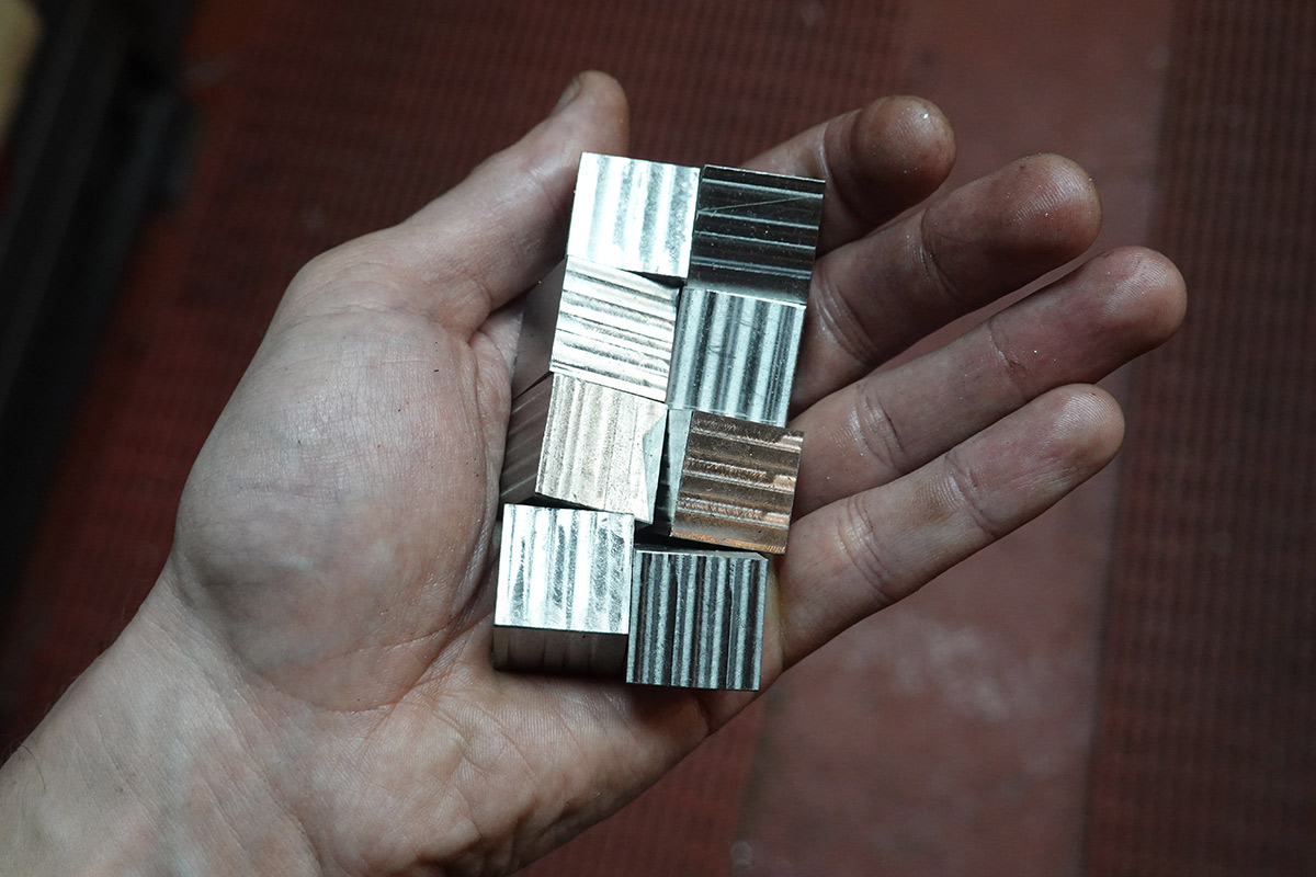
The stripey surface does have quite an appeal, and now I'm regretting leaving one side of each cube as a flycut finish. Part of the original idea was that I would surface-grind the cubes to be a mirror finish. There are two reasons I abandoned that, for one, 304 stainless is non-magnetic, and while there are magnetic grades of stainless they're harder to come by. That doesn't prevent you surface grinding, but it does make it more of a pain to hold the work. The second reason is that I don't have access to a surface grinder.
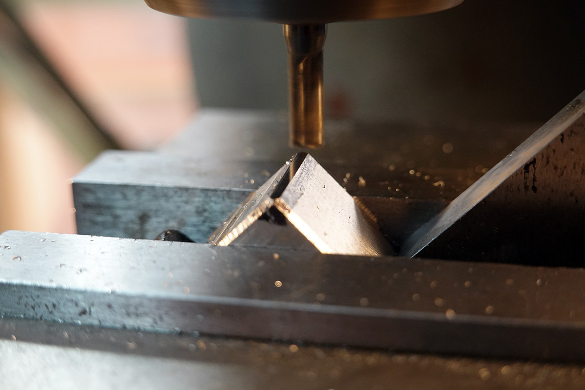
If you're paying attention, you can probably guess what comes next: it's the return of the Chamfertron 3000.

Apparently I have spoiled myself by working so much with lovely, lovely brass. The stainless cubes don't take to the Chamfertron too well. The cutting force is so much that I have to really push hard to get them to stay against the cutter, and the vibration is such that some of the swarf ends up on the sliding surface, which then embeds into the aluminium and causes problems. I had to repeatedly stop and clean the jig. It works OK if we just take very light cuts, going over every edge of every cube then advancing by 20 microns, but good grief does this take a long time.
I also suffered from the secondary and tertiary burrs, scratching and digging into the aluminium. Lightly filing each surface helps, and oiling the surface made it just about possible to get through all the cubes. The nominal chamfer size was meant to be 1mm, when I reached about 0.8mm I decided that was probably sufficient. If I had known what a pain it would be to chamfer this way, I would have maybe rethought the process. Perhaps an upgraded jig. We could call it the Chamfertron Extreme.
At the end of the second session, with my hands covered in tiny stainless splinters, we had eight cubes considered chamfered.

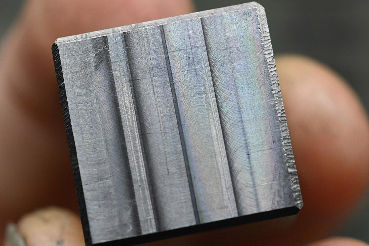
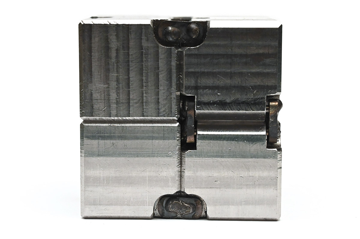
Some of the toolmarks act like a diffraction grating. It's very hard to photograph, but at certain angles we get quite strong rainbow colours in places.
The macro lens also reveals just how, err, "textured" some of our chamfers are. But lookit pretty colours! They dance as we angle it into the light.
Hinge cutouts
Start of the third session and I marked all of the least-good chamfers as candidates for hinge locations.Faced with cutting the deeper chamfers for the hinge edges on the Chamfertron, I tried to think of a better way.
What I could really do with here is a thin V-block. Something like a parallel with a V-cutout. Pretty much all V-blocks are meant to sustain clamping pressures for holding round stock, so they don't generally come in thin sizes. One option would be to use a V-block with a drift to clamp the cube, or maybe clamping multiple cubes at once. Or using a 90° V-cutter instead.
But I found a 45° angle plate that sort-of works.
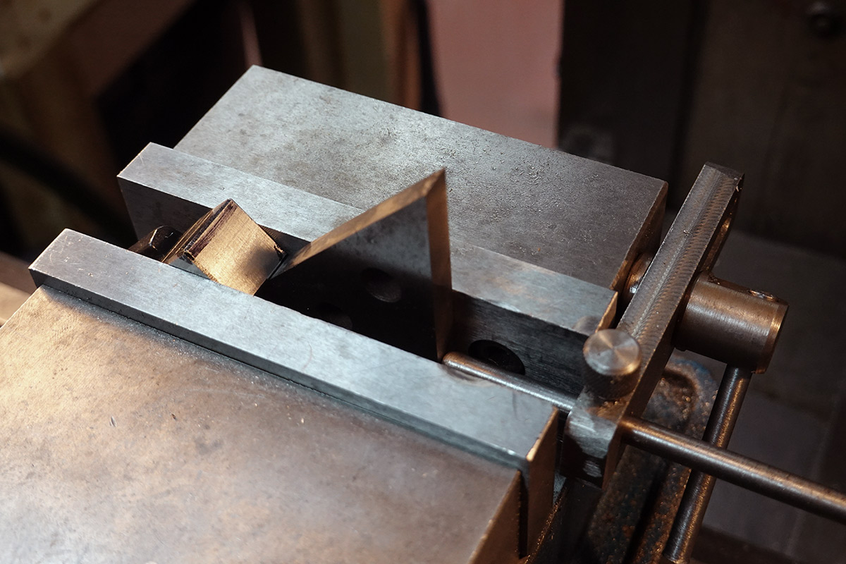
The vice's depth stop is just to stop the angle plate sliding away. The actual depth is set by a random T-nut that happened to be the right size.
The resulting chamfer is substantially better.
The temptation is to clean up every chamfer with a light pass, but it's not so simple. If we could simply unclamp, reclamp, take a cut at the same depth, sure. I cleaned up one cube this way and found the nut as a depth stop to be totally unreliable. Probably because we're indexing off the corner of it. If we need to check the depth each time, doing all 96 edges is going to take forever.
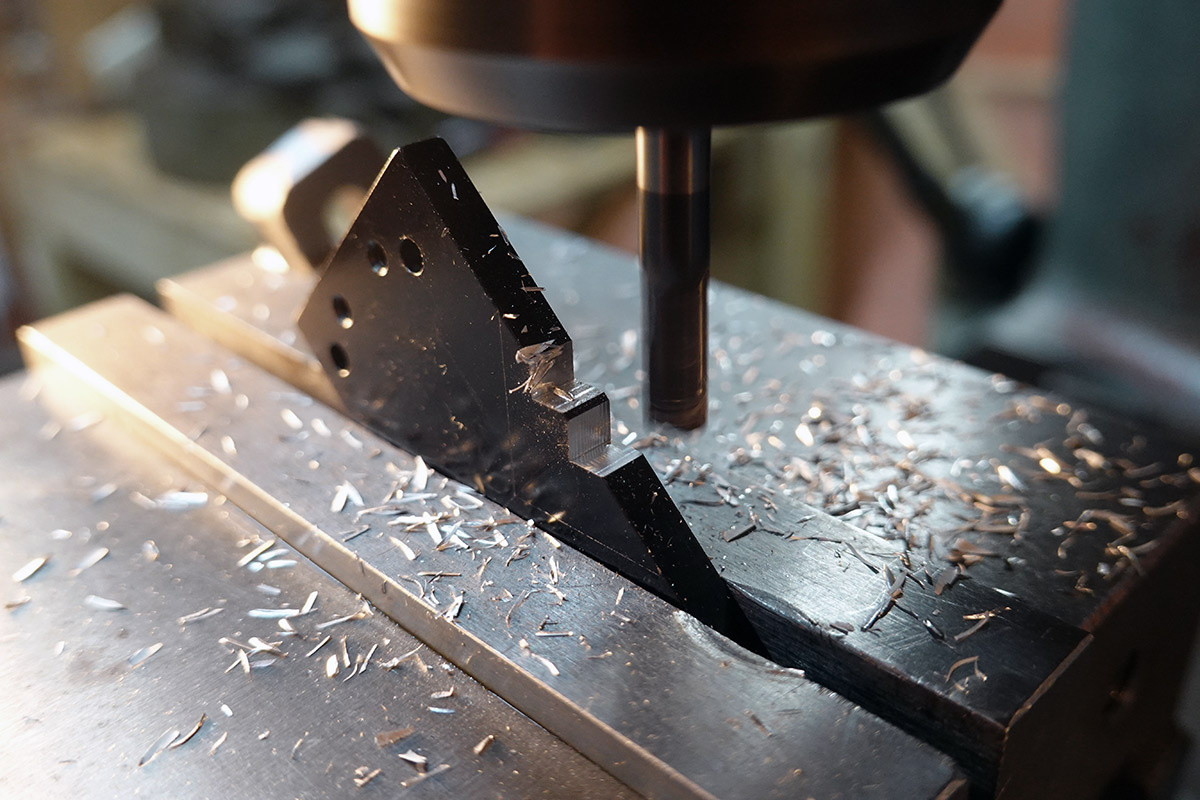
I did the deep chamfers on two of the cubes. I think judging the depth will be easier if we cut the hinge cutouts first, so I switched to that.

In theory, we can edge find once, set up the depth stop, and drop each cube in, very quickly performing the same operation again and again.
I found that having a sharp endmill made a real difference. The old one I was using left quite a burr, but a brand new one had a much cleaner result.
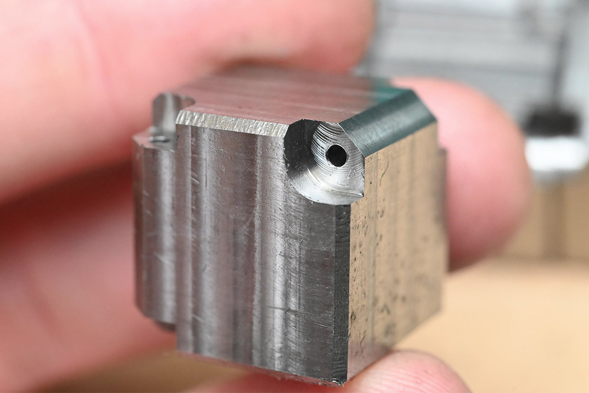
I dreaded drilling the deep holes. I have a ten-pack of 1.6mm drill bits and was prepared to break a few of them.
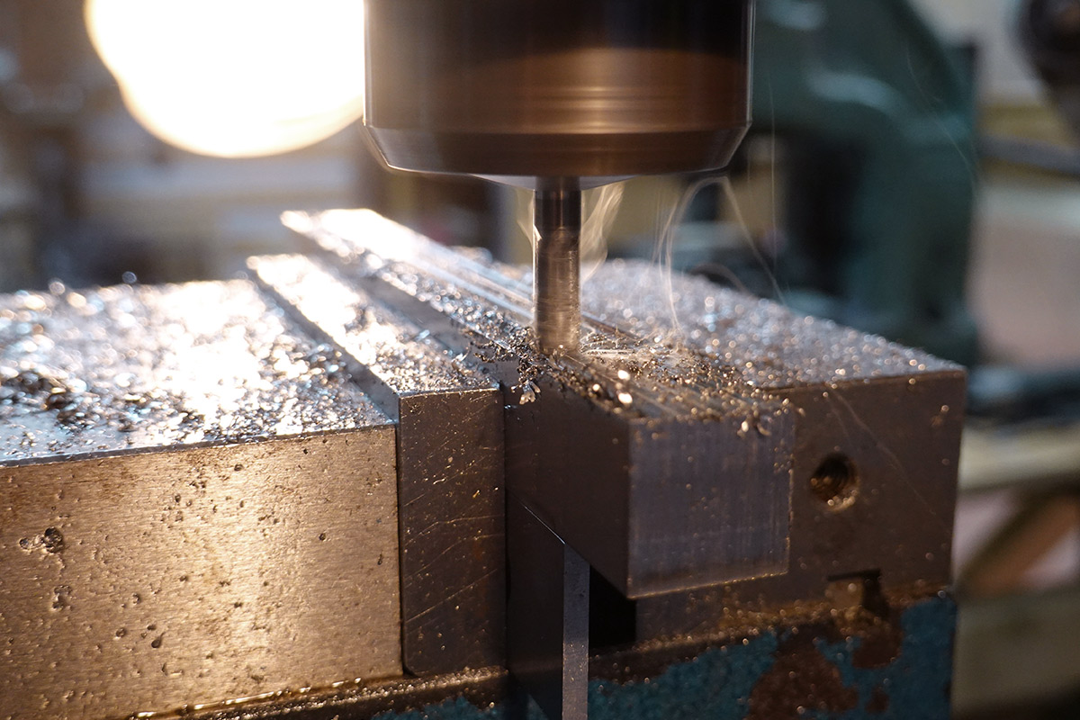
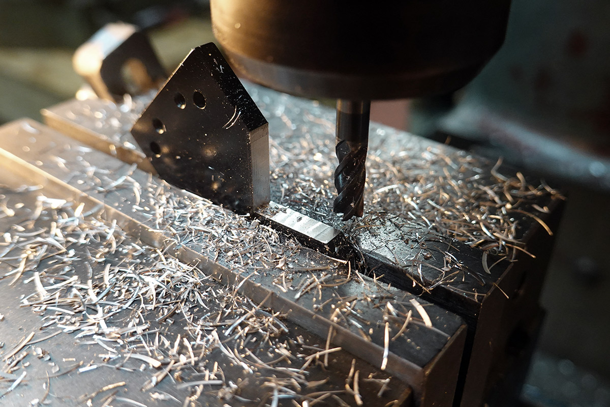
The trick to drilling holes on-centre, without centre-punching them or using a centre-drill, is pecking. Instead of starting it normally and letting the bit wander, we touch it to the surface repeatedly, so that it "starts" the hole many times at random angles, which average out. After a few pecks, there's a divot as good as any centre-punch, and we can drill with confidence.

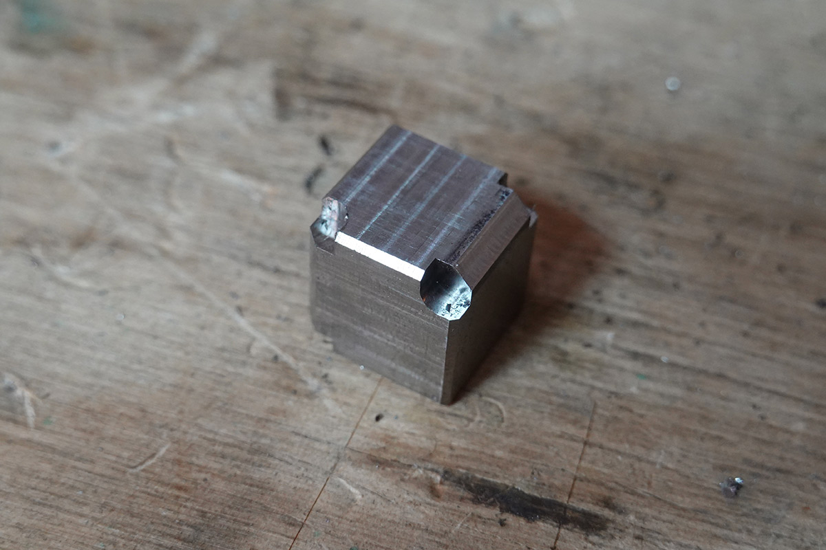
With the right technique, drilling deep holes in stainless is easy...
Hidden amongst the swarf in the picture above, you can just make out one of my pecked divots.
I did break one drill bit. For all of these I drilled about halfway through, flipped the cube over and drilled from the other side. On the very last cube I broke through a bit too fast and the misalignment grabbed the bit. I was able to recover by using the shaft of the broken drill bit to press out the remnants from the other side.
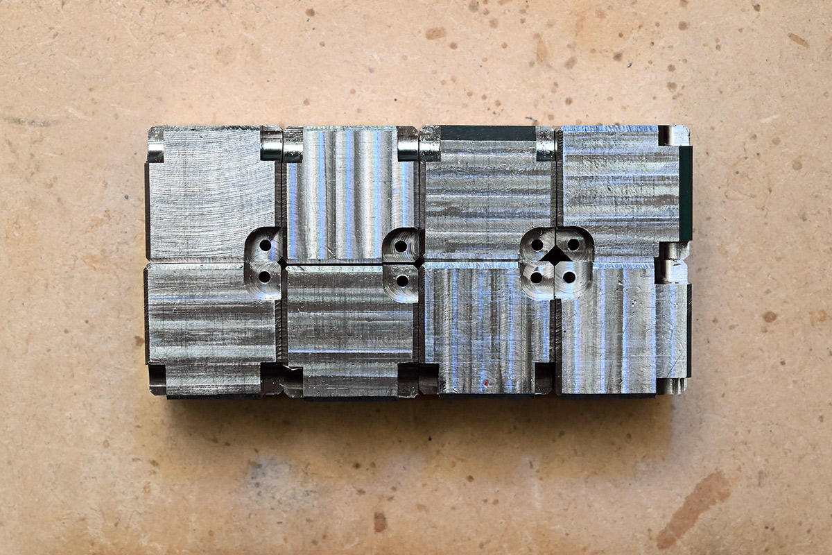
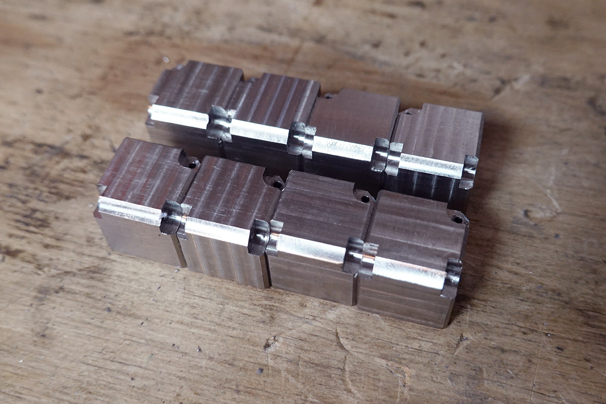
Finally, just in case you hadn't quite got the message that working in stainless takes ages, we got to the point of all sixteen holes drilled. The deep chamfers are still to cut on most of the cubes. But it's starting to look like infinity!
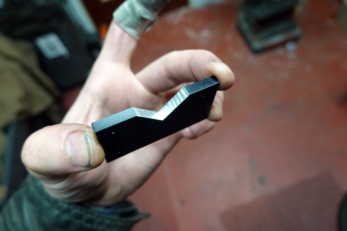
The sharp endmill really made a difference, the cutouts are very clean.
Deep chamfers again
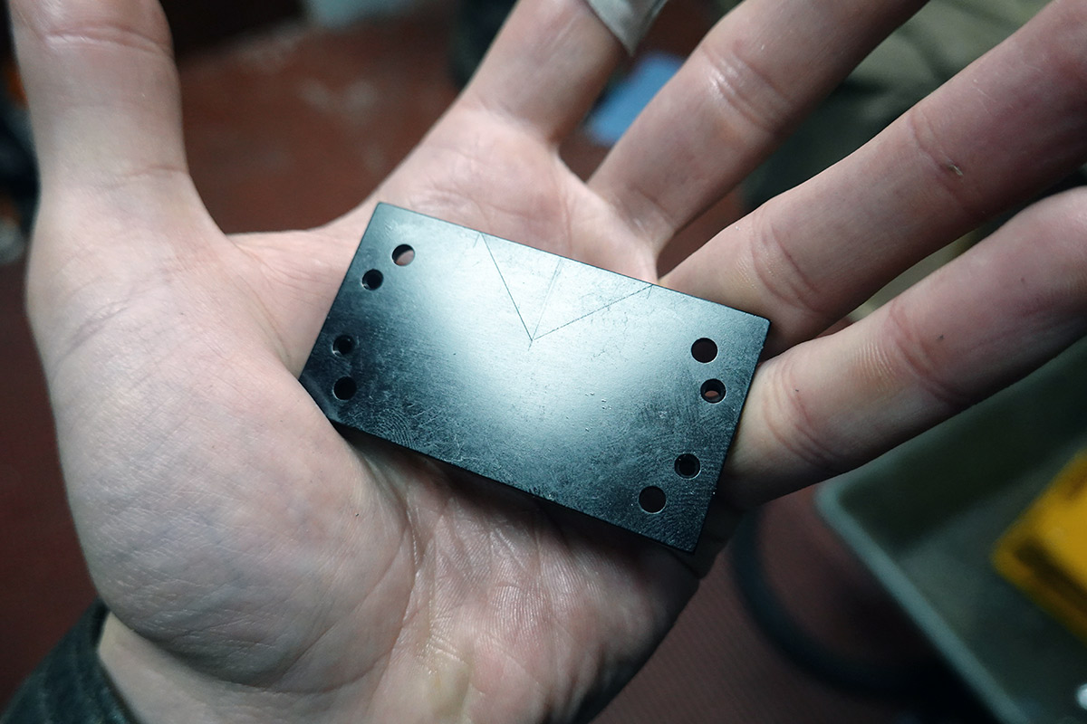
Perhaps we can think of a better way to do this. Rummaging through my scraps bin I found a lump of metal that's approximately the right size. It's already square, so I scribed a rough V-cutout into it.
In order to accurately (within the tolerance required for what is effectively decoration) align this part, I creatively used a big V-block in an inverted configuration. The top surface of the V-block mates to the rear jaw of the vice. With one of the convenient holes in the part, I used an allen wrench to apply upwards pressure into the V, as we tighten the vice.
Don't be alarmed by the plaster on my finger. It was an unrelated injury from earlier in the day.
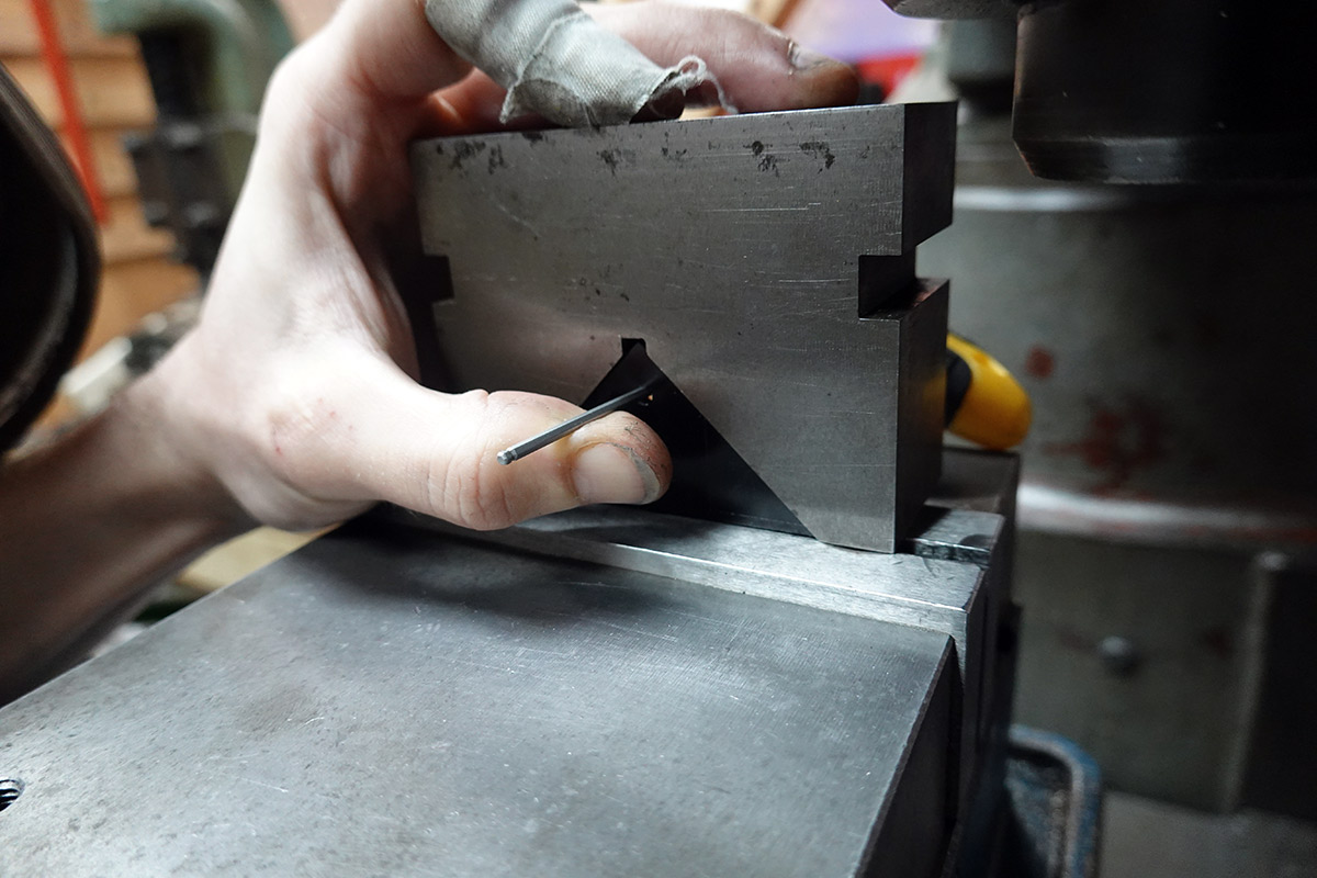
The V-block is then removed and we're ready to machine.
I'm not sure what the material is, presumably anodised aluminium, but I recall this part came out of a broken mass spectrometer so it could be more exotic.
Machines nicely. (So does a lot of stuff, in comparison to SS...)
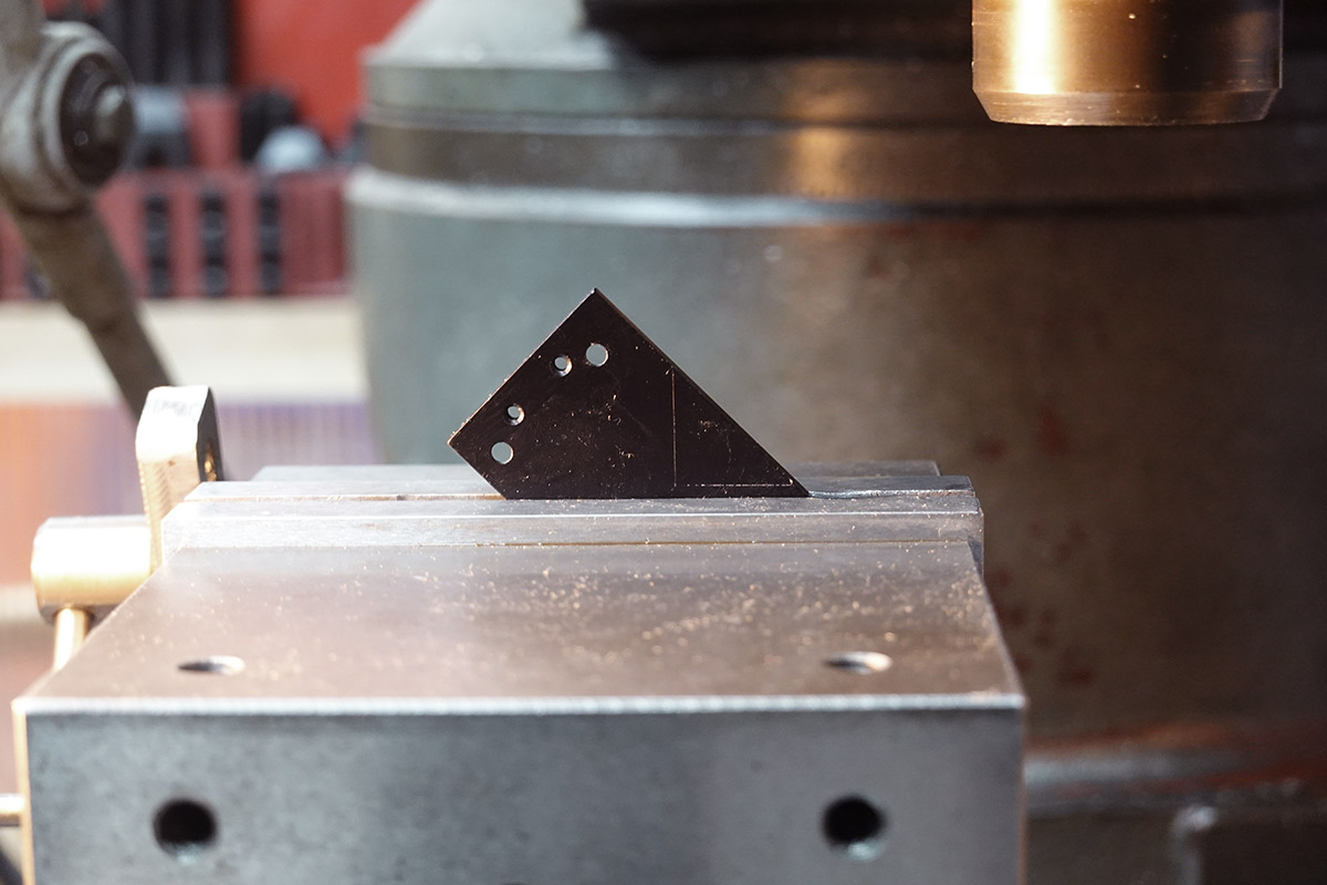
One thin V-block to order.
Aha! Now this is more like it. In goes the cube, it lands at the right angle and at a consistent height.

It took barely ten minutes to breeze through all the deep chamfers.
It was so quick that I'm tempted to redo all of the chamfers with this technique... but we have hinge parts to make.
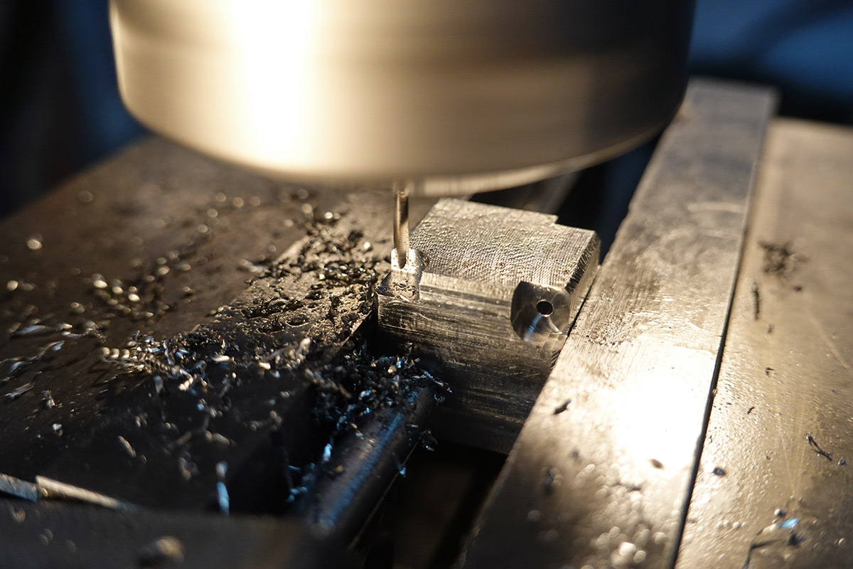
Linkages
Casual, same as last time. A 9mm strip of stainless plate, carefully clamped; we drill a bunch of holes under the guidance of our DRO. Much pecking.
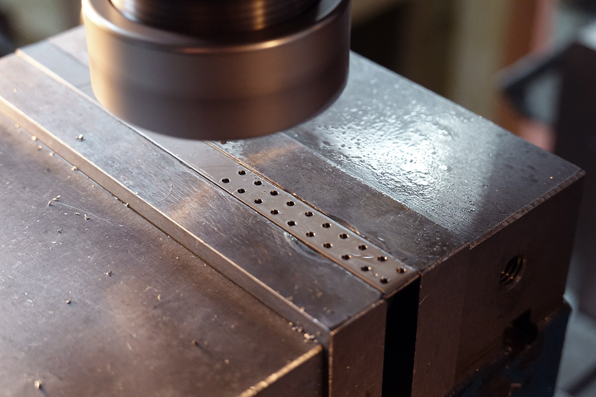
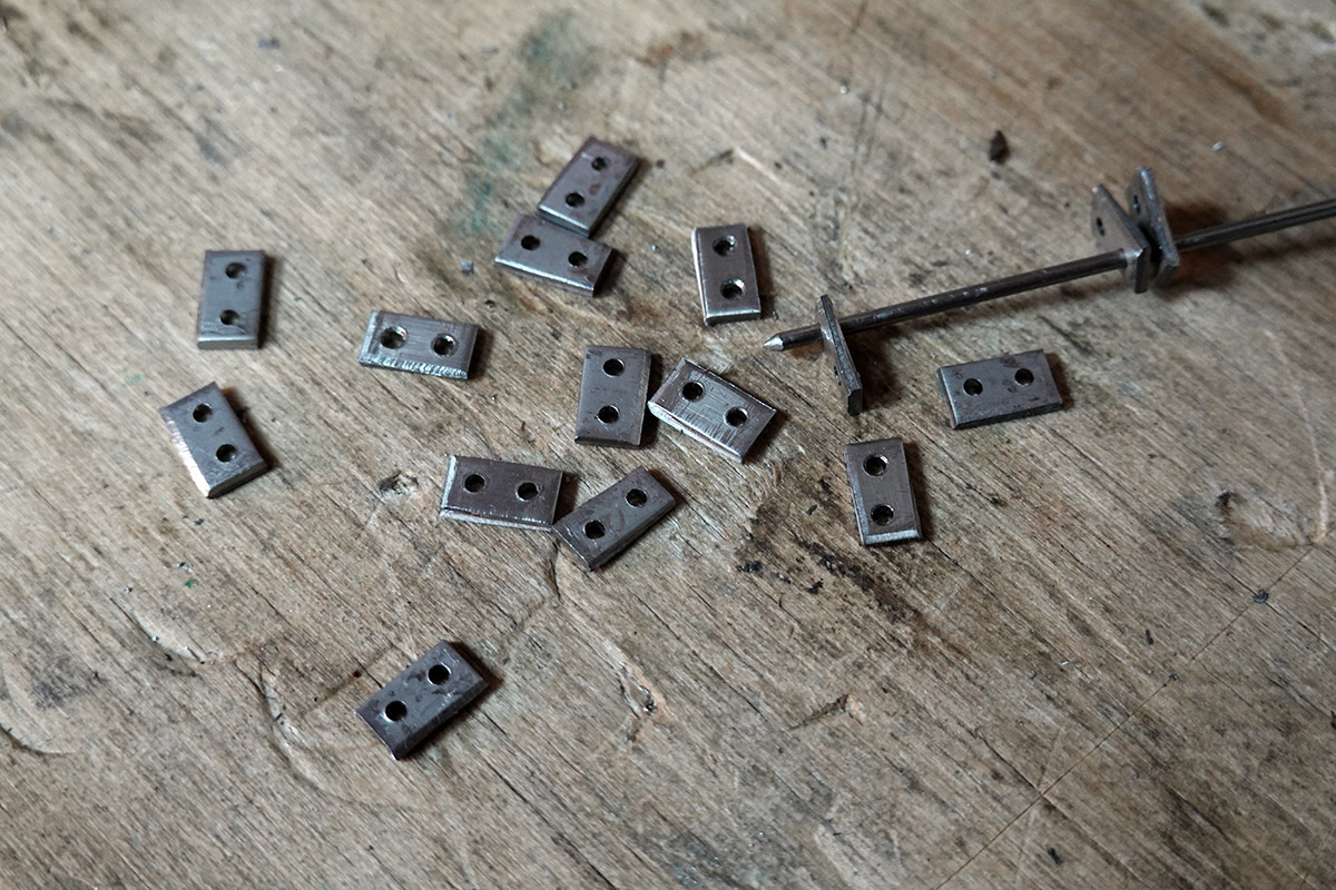
Deburred and sheared, it's at this point we realise my ten-pack of drill bits are not actually 1.6mm. They are imperial: 1/16th of an inch, i.e. 1.5875mm. Just close enough that you wouldn't notice, until you try to stick a 1.6mm rod through the hole and it binds.
This is a joyous occasion! What splendid luck. There is nothing I enjoy more than re-drilling tiny holes in stainless plate.
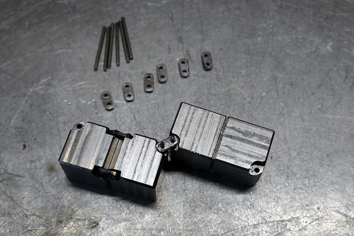
I still have the little jig I used to individually round-over the linkages last time, but in an attempt to speed things up I took a different approach. After widening all the holes, the linkages were threaded onto two lengths of filler rod.
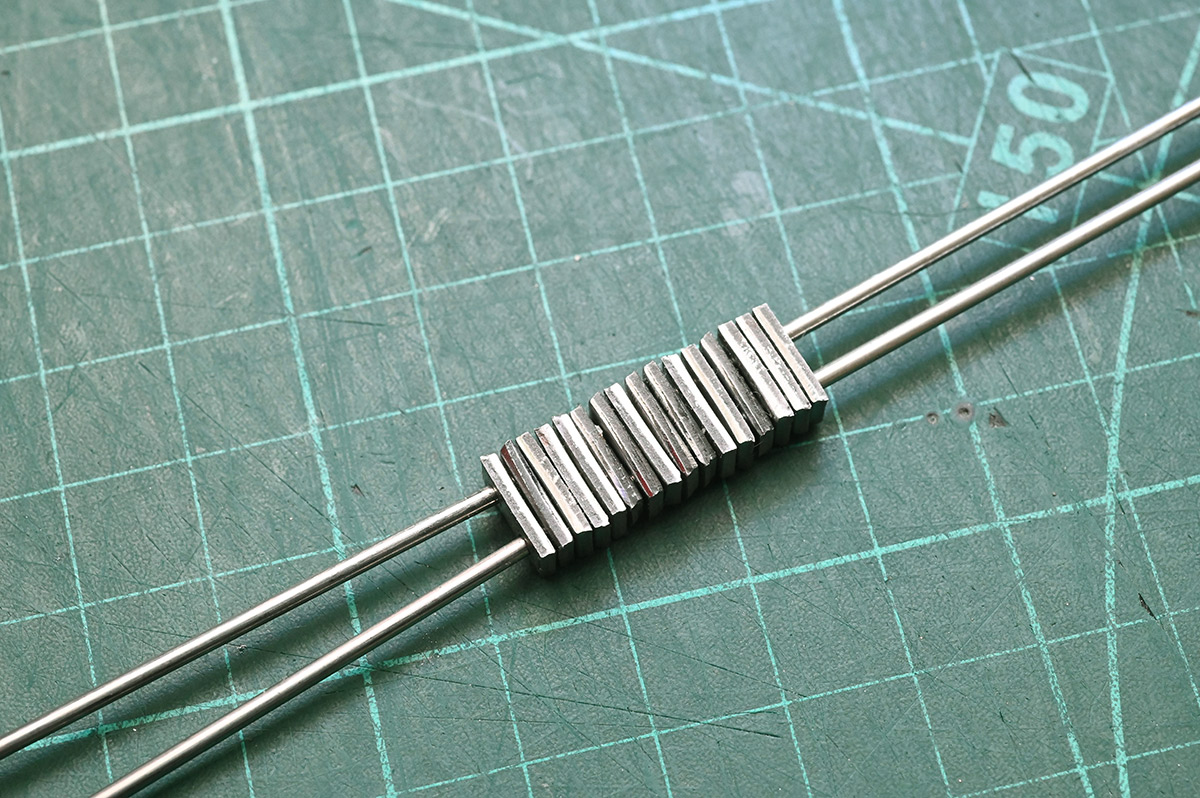
This is trickier than it looks, the tiny variations from widening the holes mean they don't all align. Some of the holes had to be widened further, and swapping the order of arrangement helped a bit. Eventually, we can chuck this in a vice and start carefully filing it into a cuboid.
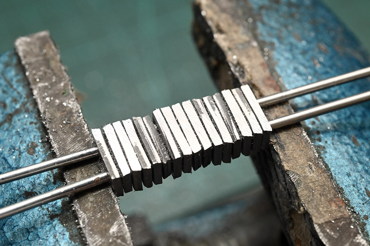
Soon it approaches a shape that can be re-clamped and further filed.
Finally, we round over the edges by eye. It took about half an hour, maybe forty minutes of fettling to reach this point. Still faster than doing them individually on the jig, but not by much. Part of the problem is that it's hard to judge progress. I'd rather have them slightly undersize, or else the hinges might bind.
While in the mood for filing, I took a needle file to the cubes. This was a minor complaint about the brass edition, that there were still some sharp edges, specifically where the main chamfers meet the hinge. Brass is soft enough that they mostly resolved themselves over time, but here we need to do something about it, and it's much easier before the hinges are assembled. A few strokes of the needle file on each edge, and a deeper chamfer either side, should do the trick.
Just sixty-four of these extra chamfers to apply, by eye, it'll take no time at all...
Assembly
Back to the mill. Session... five? Some time has passed.The through-holes for the hinges are not only undersized, but some of them are off centre. During the endless drilling process, I apparently knocked a handwheel and managed to drill several holes before noticing that they were off by about 0.2mm. This is no doubt why one of the drill bits snapped when it met the opposing hole.
In order to both widen the holes and correct their positioning, I bought some 1.7mm carbide endmills, with the plan to redrill these holes paying much closer attention this time. I set up the depth stop, dialled in the DRO as well as I could, and braced to chase 32 more holes.
It would be great to lock the position, but the axis locks on this worn machine are part of the reason I messed up the first time. People tend to lock the axis, then forget, and force the handwheel so the lock ends up wearing down to be pretty useless. Better to just keep a close eye on the DRO throughout.
For those holes which were already accurate, the endmill plunges effortlessly, gracefully widening it and ejecting most of the chips out of the bottom of the hole. But for the off-centre holes, it's a nightmare, the forces are uneven and the correct feed rate is vital. Too slow, and it rubs, locally heating the inside of the hole and rubbing further until the bit snaps. Too fast, and it grabs into the material, and the bit snaps. Embarrassingly I churned through multiple endmills, even breaking one right on the last cube when I thought I'd got it to a tee. I suppose that's why they sell these endmills in a ten-pack.
Eventually, I was content with every cube, and we can move on to the final assembly.

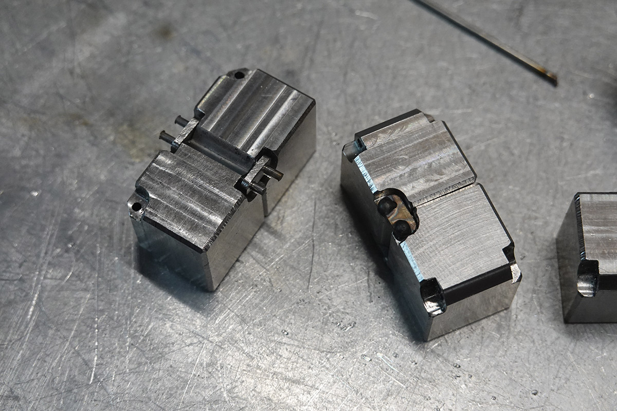
For the brass version, the linkages were welded, and a number of people pointed out that I could have peened them over instead. I investigated this. Using a nail punch and a test piece, I hammered the end of some filler rod until it looked like a nice rivet. Unfortunately, not only did it peen over the end, it also compressed the rod into the hole, binding from the expansion. This would be fine if we just wanted a permanent join, but for a moving hinge it's not going to work.
The welds will indeed be ugly, so maybe there's a better way, but while trying not to think too hard about the cumulative number of hours we've spent whittling these chunks of stainless, I figured we should go with what we know to work, so we might finally call this finished.
I did have one idea, to ball up the ends of the filler rod by heating them for the briefest moment with the TIG torch, not enough to weld them to the linkage. This is very fiddly to do consistently.

But those balls are proud of the surface, so we'd need to grind them down or something after. Honestly, it seemed easiest to just weld them properly and put up with the way it looks.
I should talk a bit about the equipment. At the old space, we had an enormous TIG welder primarily intended for assembling battleships. It took up so much room, and was impossible to move without a pallet jack, that in this new space everyone was on board with an upgrade. The new machine was acquired from an auction and on paper is much better: solid state, watercooled, and a bunch of fancy features.
However, it's missing a footpedal, and the torch seems to be some nonstandard size, so regular ceramic cups and collets don't fit it. That doesn't really matter if not for the fact that the only shroud it came with is cracked into two pieces. I "repaired" this with a cable tie, and managed to force one of my smaller collets into the torch so I could use 1.6mm tungstens. This didn't grip properly, even when fully tightened, but it makes electrical contact so it's probably fine (actually it jammed into place, and I had to use a drift to pop it out when I was done).
More annoying is using the button to start and stop the weld. The whole reason I like TIG is that it's great for tiny, fiddly stuff, but the button forces you to grip further away from the tip giving you less control. It's also a different mindset, with the pedal you can simply dial back the power in real time instead of having to set up the desired current in advance. The ramp-off time catches me as well, when you let go of the button it continues to weld for a set time that you have to anticipate. One nice thing about the old machine is that there really weren't that many settings, whereas here there's a complex interface with loads of variables.

One marvellous improvement is that this welding machine doesn't ring the doorbells when you strike an arc. A non-zero amount of electrical interference was given off by the old machine.
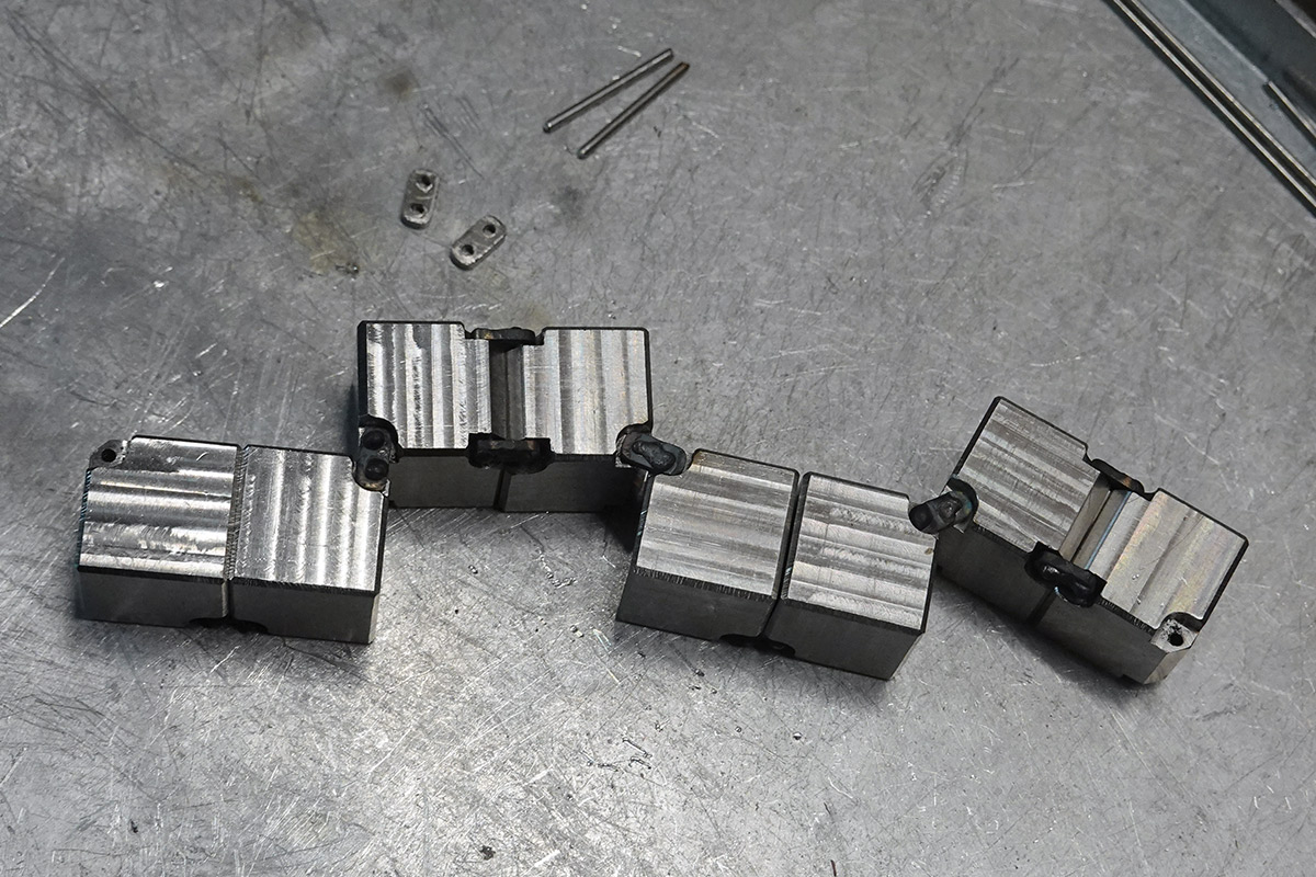
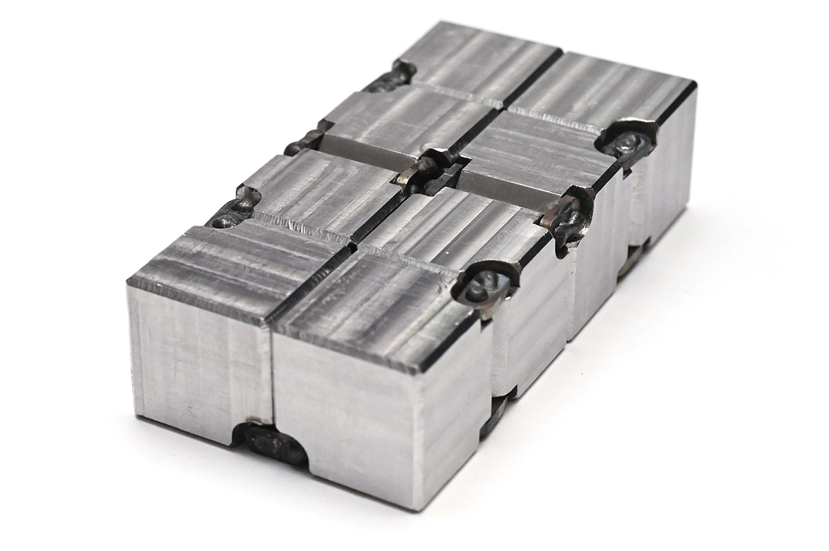
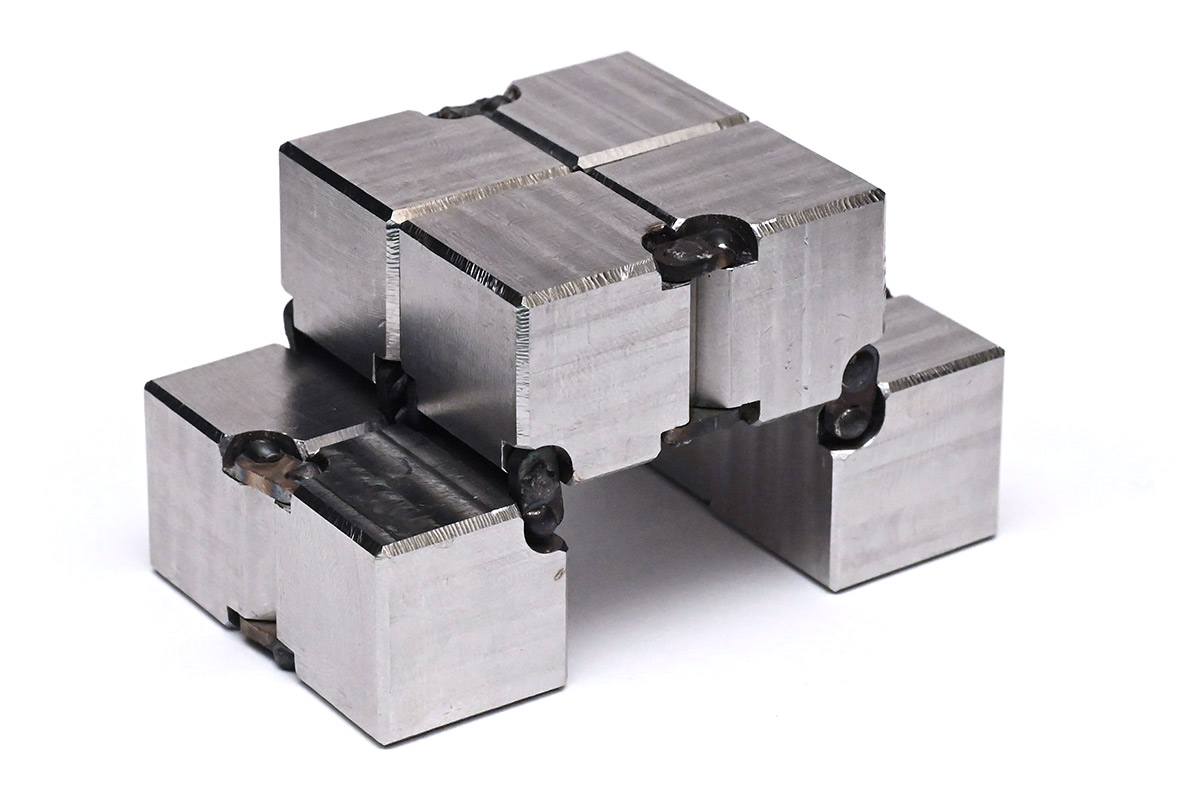
To the surprise of no-one, this step is substantially easier when you have a reference infinity cube to hand. It requires no brain power to get the cubes in the right order.
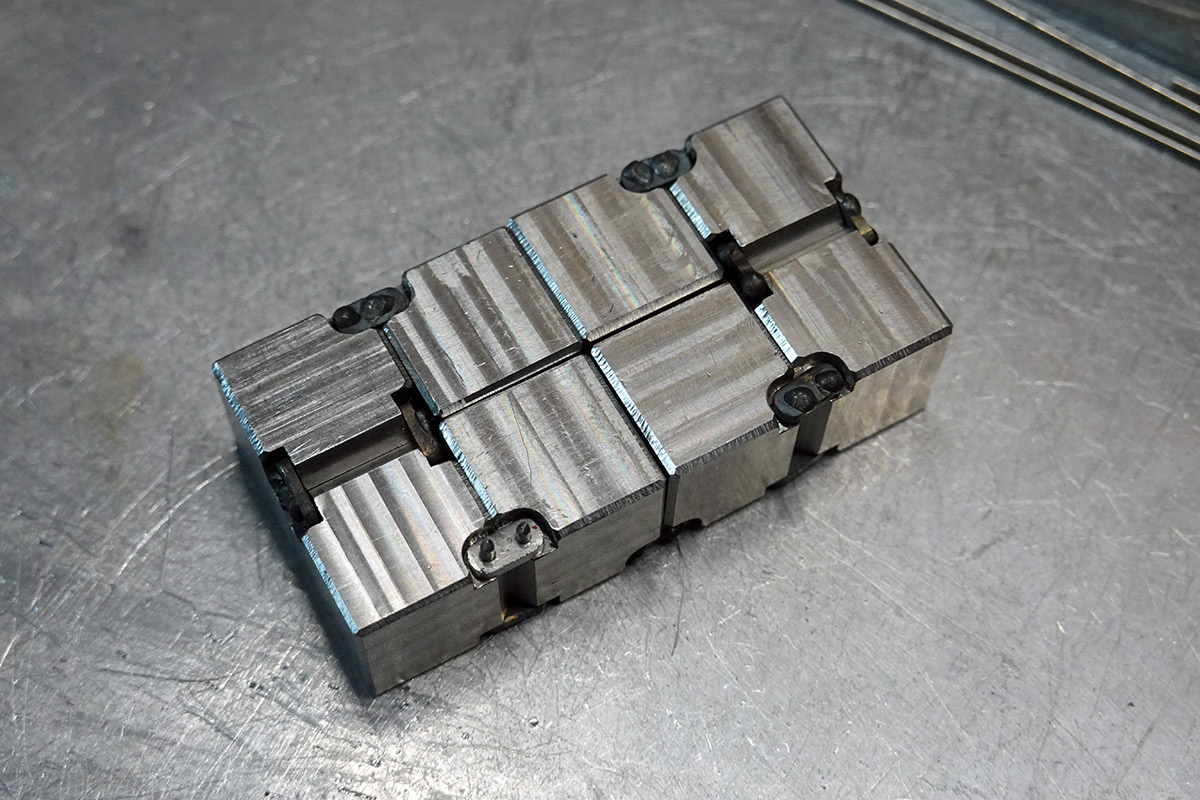
Done!
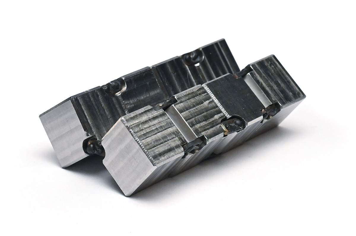
There are still some stiff spots for some of the hinges, I have no doubt these will run-in after enough actuations.
The little chamfers around the cutouts make a big difference. Run a thumb along a hinge and it's noticeably smoother than its predecessor.
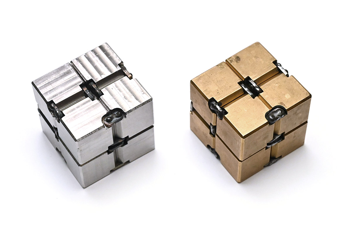
The brass one has seen a substantial amount of usage. Actuated a few times a second, for hours at a time, over the course of a few years, as evidenced by the amount of grime around the hinge cutouts.
The hinge cutouts are intentionally larger than the linkages, leading to a fairly loose feel, somewhat like a chain. It would be interesting to try links that fit snugly. I'm not sure if a precise, rigid mechanism would be more or less satisfying.
Importantly, after playing with it for a while, I can confirm that there's no residue left on my hands. All praise the stainless steel gods.
To conclude, that is probably vastly more detail than anyone needed about building a stainless infinity cube.
After posting the first one, a few people inquired about commissioning me to build another for them. Perhaps this page can serve to explain why, were I to do that, it would end up very expensive.
Could we cnc it? It wouldn't have the handmade feel or the rustic blemishes, but sure. Maybe I'll try that for the next one.