
Motorised Camera Slider
7 Jul 2024Progress: Complete
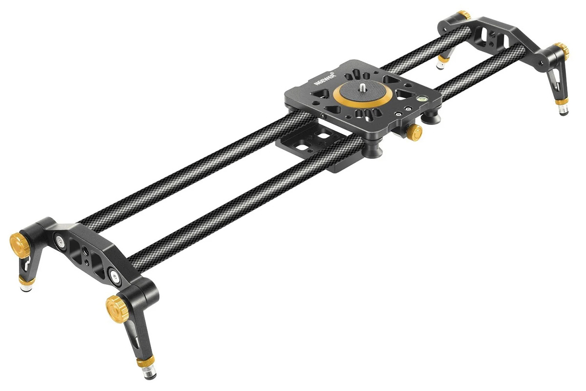
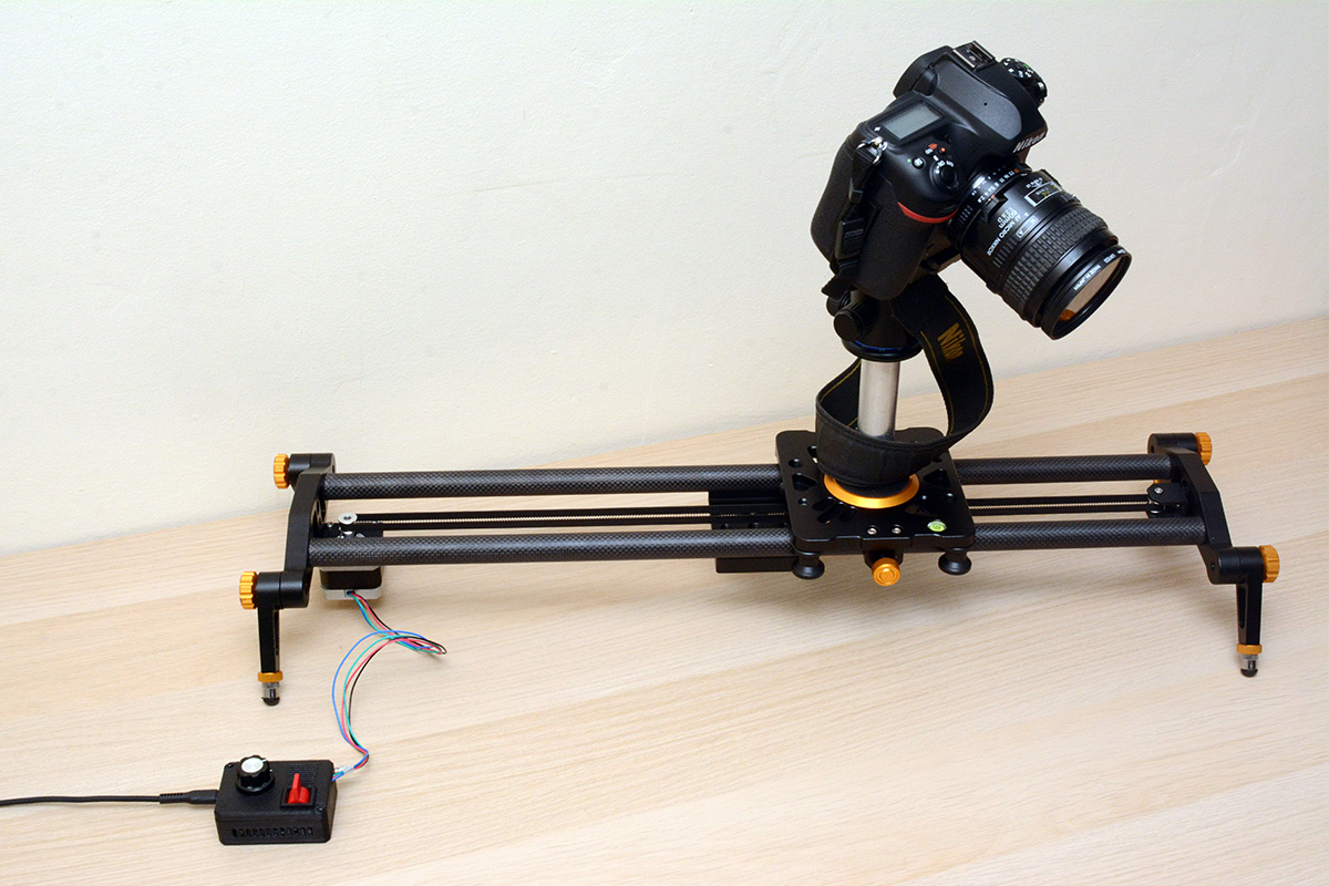
Compared to some of my projects this may seem a little mundane. Many people have built motorised camera sliders, probably far better than the one I'm showing off here. This is just a simple conversion to turn an off-the-shelf manual slider into a motorised one.
Motorised little sliders are now available for quite reasonable prices, so it probably makes no sense at all to be building one if you just want the end product. Part of the motivation here is that I own a manual slider (which just predates the influx of cheap motorised ones) that has reasonably nice rails but is almost impossible to use. The construction means there's very little friction, but the tiny resistances you do feel are inconsistent so it takes great concentration to get a smooth shot. All it would really need is a controlled resistance so you can apply more force to a slow slide. There is a brake but it operates essentially as on/off. Some manual sliders have a belt drive to a little flywheel, I expect that helps a lot.
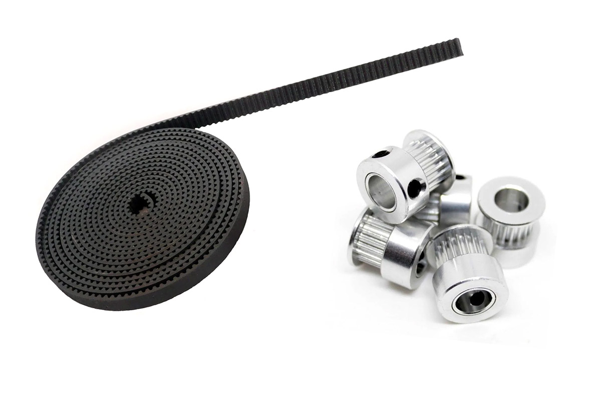
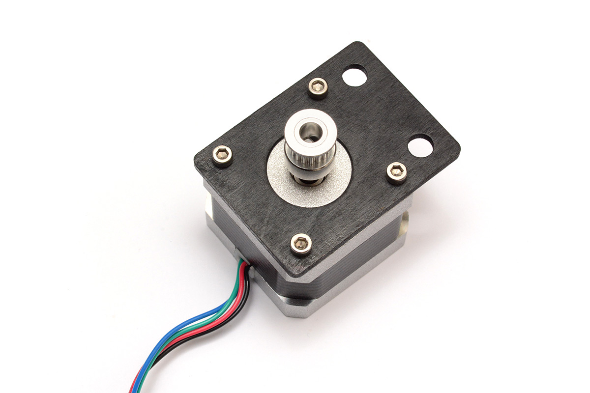
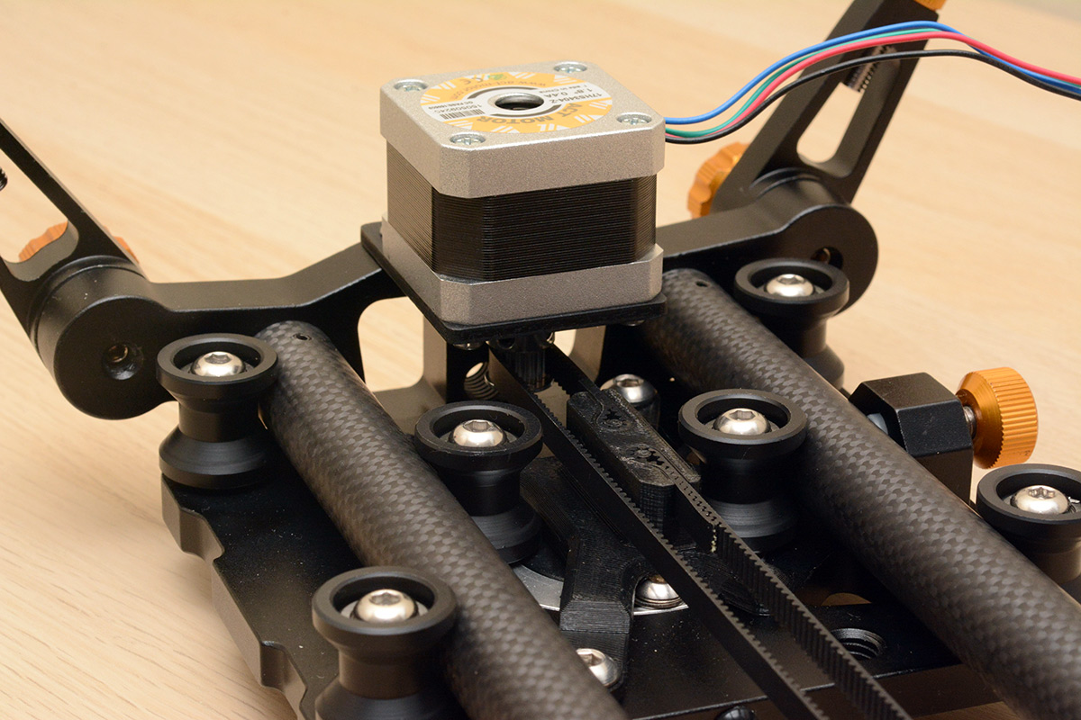
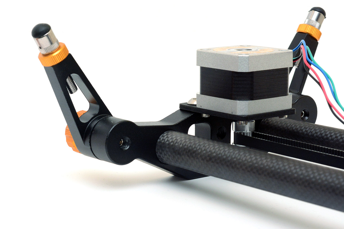
The first challenge is mounting a belt drive and a stepper motor to it. Ideally in a way that doesn't poke out or interfere or reduce the travel in any way. The belt, pulleys and stepper motor are abundantly available as spares for 3D printers. I went with a GT2 6mm belt and two 16-tooth pulleys, the idler has a 3mm bore and the drive pulley fits the 5mm shaft of a stepper motor. The stepper is a NEMA 17 with 1.8 deg step angle. All bog standard 3D printer stuff.
The slider has plenty of mounting points, but they're all tripod threads: 1/4-20 and 3/8-16. Here in Europe, I only have metric bolts to hand. In the past I've ended up making my own bolts, tapping them with imperial threads on the lathe, because I was too impatient to order them and wait for them to arrive. As a sign of my maturity, I ordered some 1/4-20 bolts and diligently waited.
OK – that's not true. When I decided to build this, I ordered the bolts and then did everything else I possibly could, to the extent that the moment the bolts arrived I fitted them and the whole project was finished.
Mechanicals
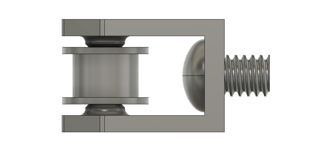
There are three parts to produce: a mount for the motor, a bracket to hold the idler pulley, and an attachment point to the carriage. I'd normally go straight to OpenSCAD for this, but another project has me looking back into Fusion 360, and I figured this would be a good quick project to remind myself how to use it. I've done some reasonably complex stuff with Fusion but it's about five years since I last touched it. In the intervening time it seems they have hobbled the free tier somewhat, which was to be expected really.I considered having the belt run through the large openings at each end and mounting our extra hardware outside, but the carriage is wide enough that this won't be necessary. We'd have to do an exceptionally bad job for this to end up eating into the travel. The idler pulley is a simple bracket.
Obligatory embeddiment:
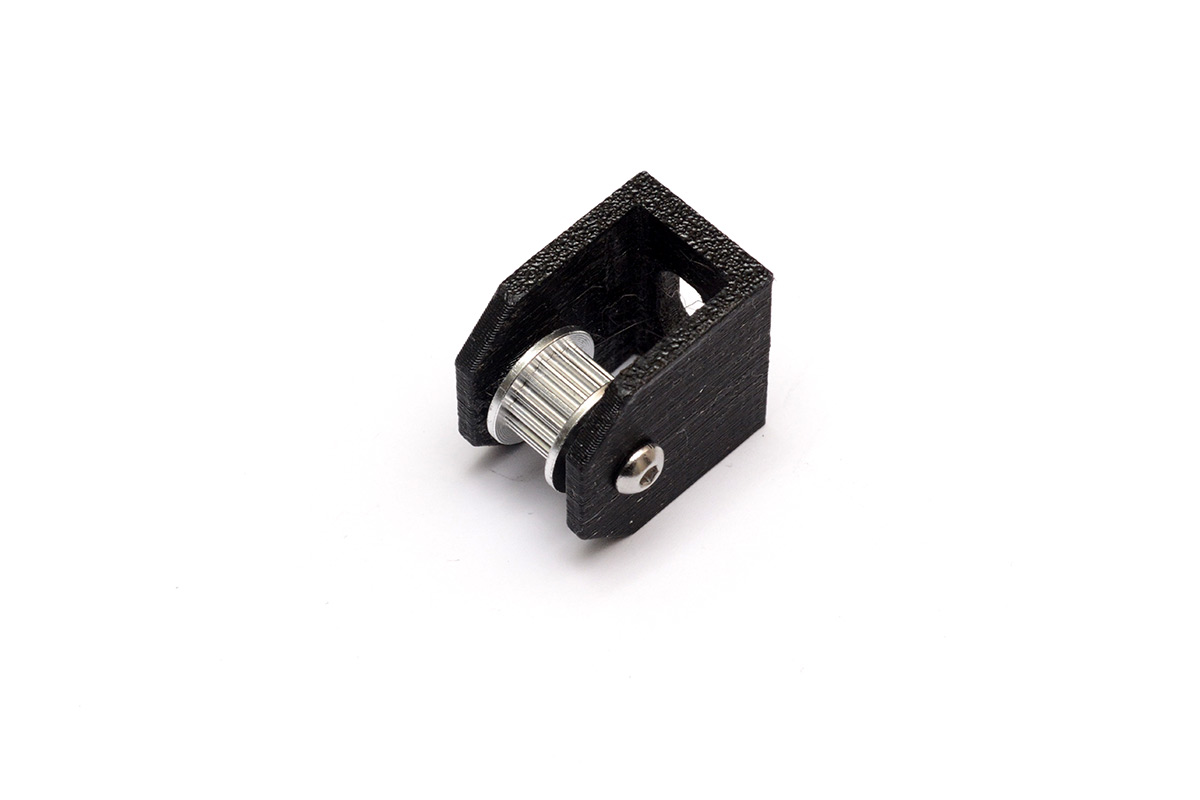
The bolt head is wider than the pulley is tall, so protrusions are needed to contact the bearing, and the bolt hole is an oval to let us slide the bolt head past these. The bracket is 3D printed in PETG, in the plane that gives a little more strength to it.
In the 34 minutes it took to print this bracket, I was able to fully design and laser-cut the motor mount with time to spare. This is in 3mm plywood, which is perfectly acceptable for this application, aside from its appearance. To give this a more professional feel, I gave the wood a quick coat of black spray paint.
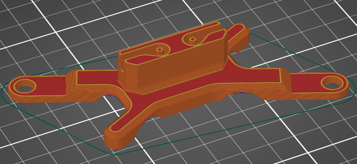
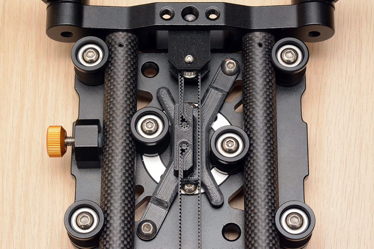
Finally the carriage attachment, this a more complex shape. We need to attach over the bearing tension mechanism, and grab both ends of the belt, holding it in line with the pulleys at each end.
Following a lot of careful measurements with the callipers, I came up with this shape.
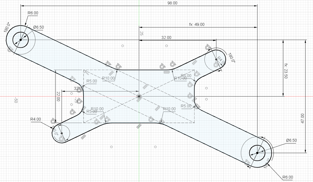
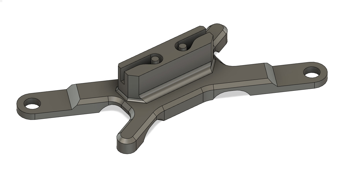
With just the 1/4-20 bolts there's only two places we can attach, but to stop the part rocking I added another two legs that will hopefully give it some stability. The underside has cutouts for the rotating tensioning mechanism to move freely if ever it needs to, even though I don't expect to be fiddling with it any time soon.
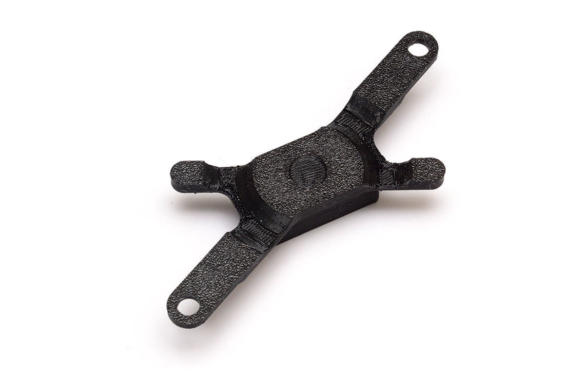
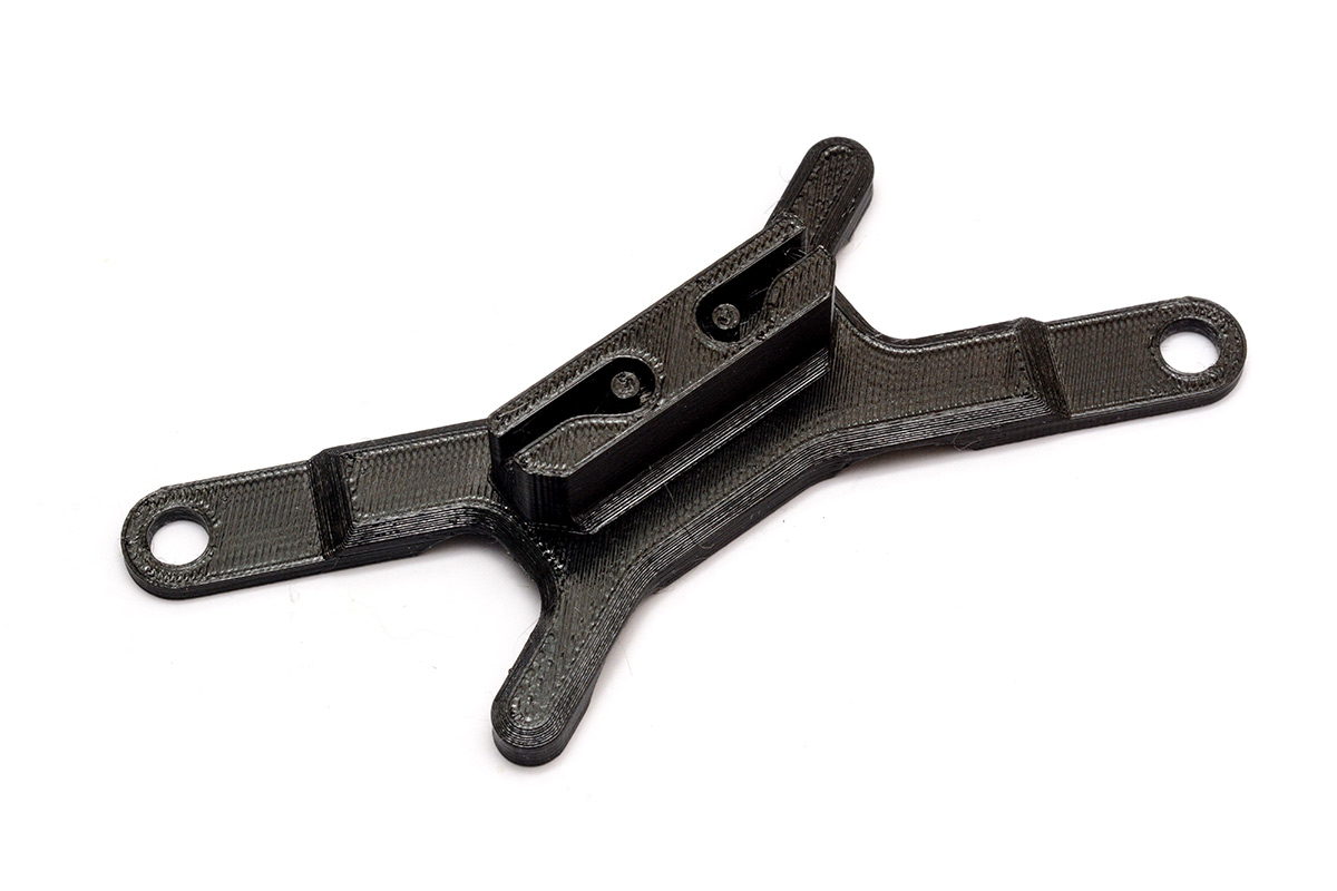
The belt clamp was just eyeballed with splines after a couple of measurements. Lacking confidence in my own abilities, I did a test print of just the clamp first.
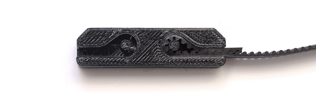
It functioned perfectly, so I then printed the whole thing. There are some large overhangs, I opted to forgo support material since it will print fine regardless. We might lose one layer but that's a small price to pay compared to an extra 20 minutes of printing time. Using the laser cutter really does hammer home how slow 3D printing is.
The part took about 1 hour 20 minutes to print.
(The imperial thread bolts still hadn't arrived, so I had no justifiable reason to be impatient, but it still feels irritating to wait.)
When the bolts finally did show up, my measurements were impeccable, and the assembly process was somewhat anticlimactic.
Electronics
We primarily want to do some very slow slider shots. Quick ones are a bit easier to pull off by hand. In recent years, a number of "silent" stepper drivers have appeared, which are excellent and exactly what we need for this. I got a TMC2209 on the de-facto standard stepper driver breakout board.
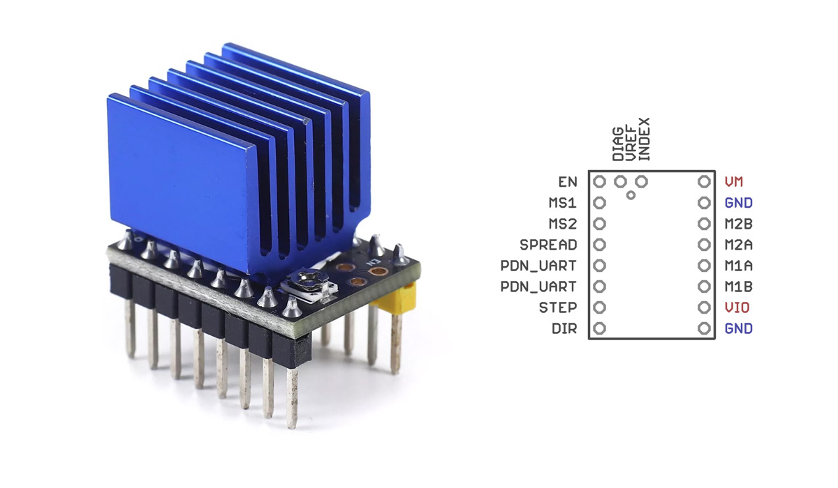
This thing will work like a standard stepper driver if you want it to, just provide DIR and STEP signals. It's preloaded with fairly sensible defaults. It also has some configuration pins to set the number of microsteps and the reference current, but the main feature is a serial interface that lets us configure all of the parameters. An appealing feature is that it can monitor torque on the stepper motor, which can be used to detect a crash or to home the carriage without needing limit switches.
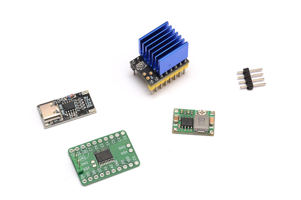
However to begin with I just wanted to make the motor move. We need to give the driver two power supplies, one for the motor coils and one for its logic. I immediately turned to a USB-PD breakout board. I've been using these a lot lately. This isn't a buck converter, it's just a tiny chip that does the negotiation to ask a USB-C power supply to give us nice voltage. A solder bridge lets us choose one of 5V, 12V, 15V or 20V.
Taking the 20V for plenty of power (I think it's fine for this size stepper to be run at up to 48V) we then need to drop it to a safe level for the logic, and our processor if we add one (we will). A linear regulator works but will be burning a lot of power. Instead I grabbed another cheap module, a tiny buck regulator. I have loads of these in my drawer, they're so useful. A trimpot lets us set the output voltage to 3.3V.
The stepper has a JST connector, but it's a 2.5mm pitch so we can cheat and plug it into some .1" header pins.
Finally I'll grab a CH32V003 on one of my homebrew breakout boards.
I suppose we also need some controls. A knob to set the speed at the very least. This is basically dictated by what parts I have on hand, if I had thought ahead I would have ordered something here too. I was thinking a three-position lever switch, for forwards, backwards and centre-off. The closest thing I have is a lever switch that's spring loaded, always returning to the middle like a joystick. This will have to do.
It's easy to be paralysed by indecision when you start sticking bits together. One of the nice things about doing short inconsequential projects is that nothing really matters. Sure there's probably a better arrangement but it's totally fine to start sticking things down and roll with however it turns out.
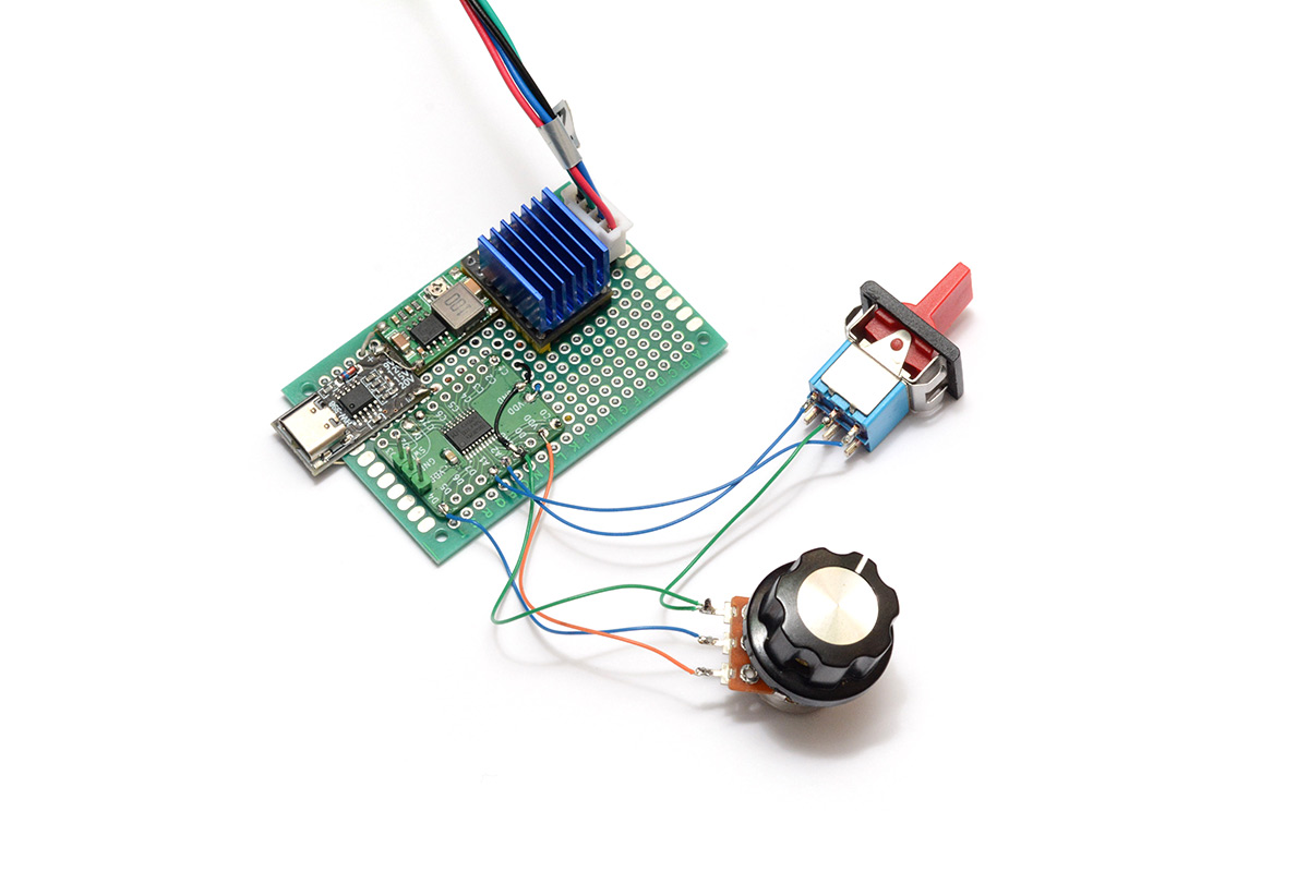
I changed my mind and ended up wedging the step-down module in at the top there but it's fine, just need to be careful we don't short the 20V line to anything sensitive.
I was tempted to keep the stepper driver removable, but that adds a lot of height to an already tall module. Famous last words but I doubt we'll need to replace it.
Software
The plan was to wire up the UART interface and play with the fancy features of this driver but all we really needed was to turn the potentiometer reading into a pulse train to the STEP input. There are a couple of modes to this module, some of which are more silent than others, plus a low-power mode that reduces current when less torque is needed. The default settings switch between two modes depending on how fast we're stepping it. It gets noticeably quieter when I drop below a certain speed.We can configure the number of microsteps either through software or through pin configurations, but the default seems totally fine. Pulsing as slow as I'm comfortable, about once per 50ms, moves us at less than 1mm per second, while the fastest I can go gets us about 10cm per second, faster than I'd ever need this for.
In terms of an interface, since the switch is a momentary one, I went with the following, implemented as a state machine:
- Tapping a direction starts the carriage moving in that direction at the selected speed
- Tapping again stops it
- Holding the switch down in one position moves the carriage at max speed in that direction
I doubt the "fast move" mode will be that useful but it reminds me a little of the power feed on the milling machine which I always had a soft spot for. I specifically disable the driver when it's not moving, so the carriage is free to move by hand, meaning that fast move isn't a requirement. The main reason I disable the driver is that leaving it for any length of time burns enough power for the motor to start warming up. I like how much torque this has and don't want to compromise on that, but when it's not in use there's no need for it to be tensed up.
When I came to assemble it, I found this simple software was already way beyond anything I needed. It runs super slowly and super quietly. Anything else is a bonus but just doesn't matter. One thing I probably should add is the stall detect / crash detection, it has enough torque that it would probably start skipping teeth and tearing itself apart. We could potentially home it on power-up, and remember the distances travelled to stop automatically. A slight problem with that is we lose position when the driver is disabled. There's a chance I'll come back and implement this, but for now this already beats anything I could have hoped for.
Assembly
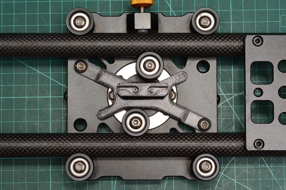
When the imperial bolts arrived I threw it all together. The stepper mount works exactly as expected, it's almost as if I knew the dimensions of the bolt heads before they arrived.
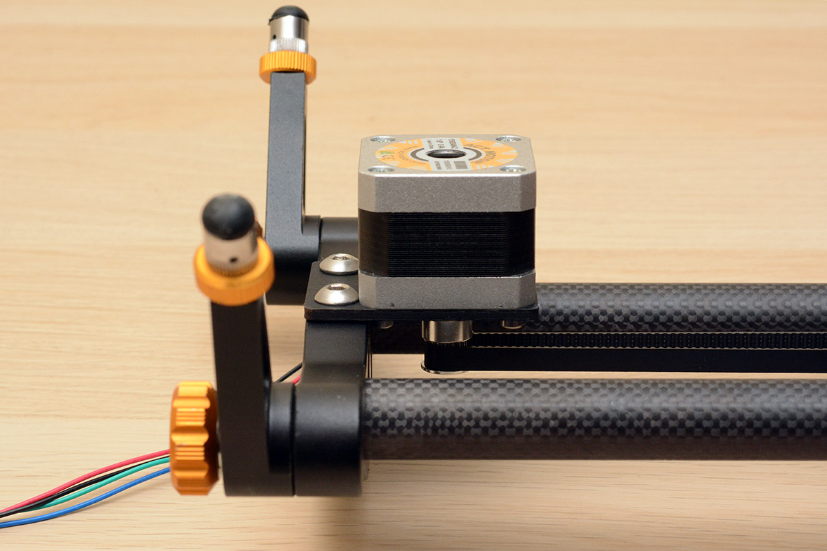
With the motor mounted this way, the legs are still able to fold up, so the whole thing still fits inside the soft case it came with.
Belt is parallel for the full length, no interference, no loss of travel. I tensioned it just by pulling it into the clamp, it doesn't need to be super taught. Running the carriage up to each end confirms everything's aligned.
Case for the gubbins
To save filament, hasten printing time and just to remain consistent in style let's make this case as small as we can within the time available. I think that means cutting an L-shape out of the protoboard so the big switch can sit in the gap. I very roughly modelled the main features of the circuit and sketched a case around it.
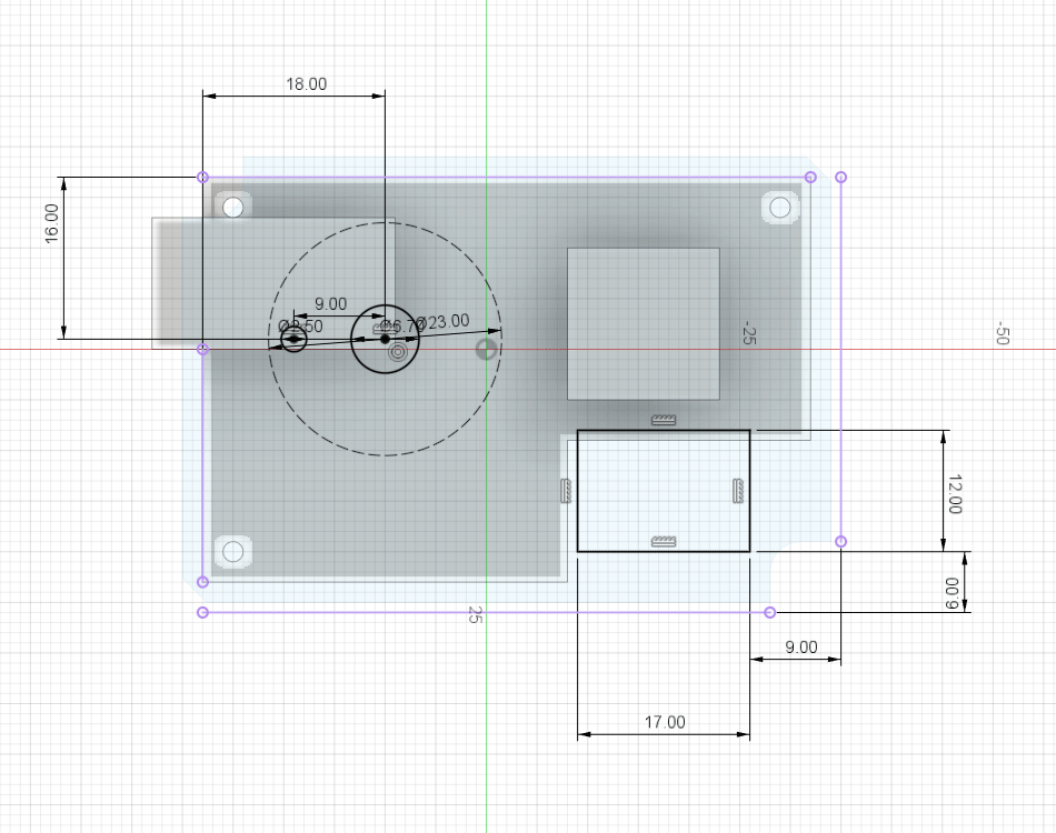
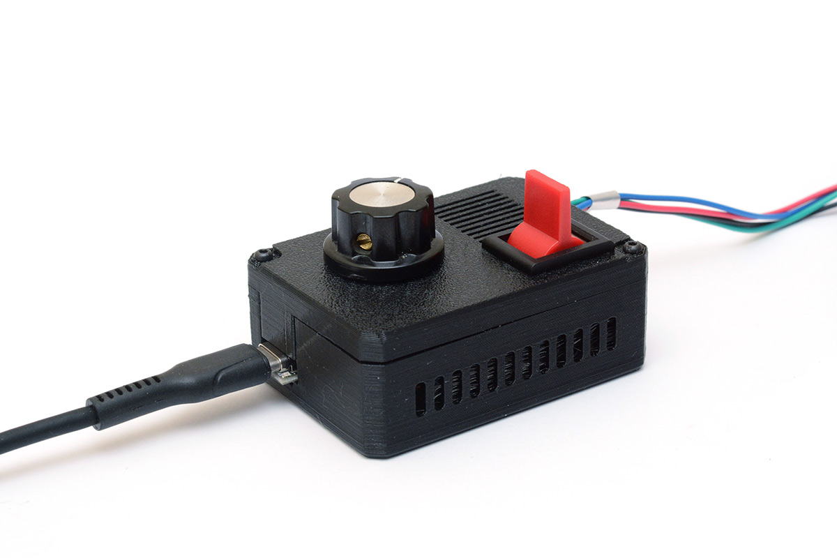
Naturally the USB-C port needs to stick out. Screw holes appear with a progressive overhang so no support needed. For something like this we can just slightly undersize the holes – 1.8mm for M2 screws – so they form their own threads that will easily be good enough.
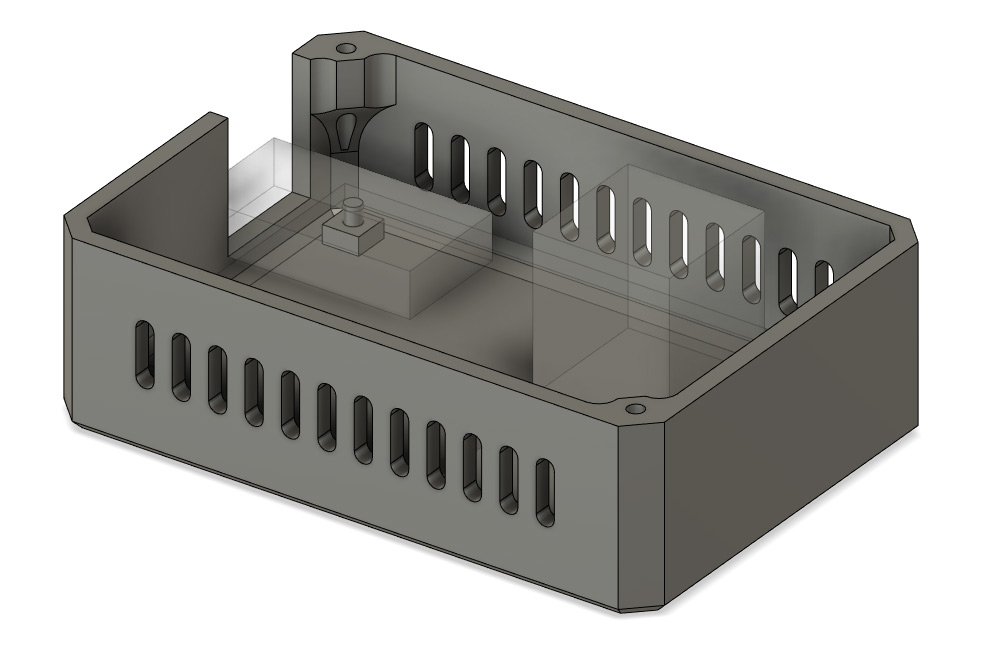
There are studs that reach up and support the circuit. These will be just the gentlest press fit into the protoboard, that'll be plenty to hold it as the forces on the USB port will be perpendicular.
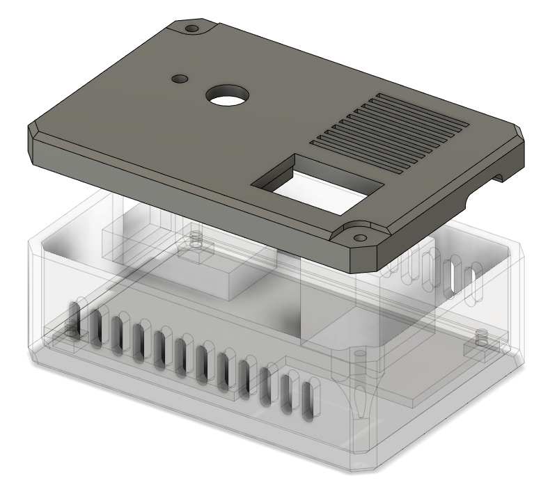
As we send that to the printer, the goal is to design the next part before the first one finishes printing. The lid will clamp down on the USB port to hold everything fast.
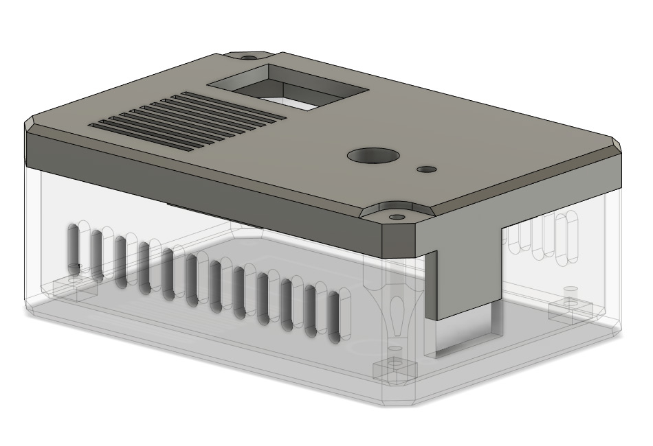
Added plenty of air vents, especially over that big blue heatsink of the stepper driver. I've not noticed any warmth at all come off of it while it's running but more airflow can't hurt.
Positioning for the knob and the switch was dictated by squeezing it all into a tight package. I could maybe have centred the knob, but going deliberately off-centre felt more natural, and gives a little more clearance for using the switch.
That was sliced and sent to the printer as soon as the first bit finished.
The fastest and best way to cut protoboard is with tin snips. If you're feeling fancy, as I was here, you can clean up the rough edge with a file.
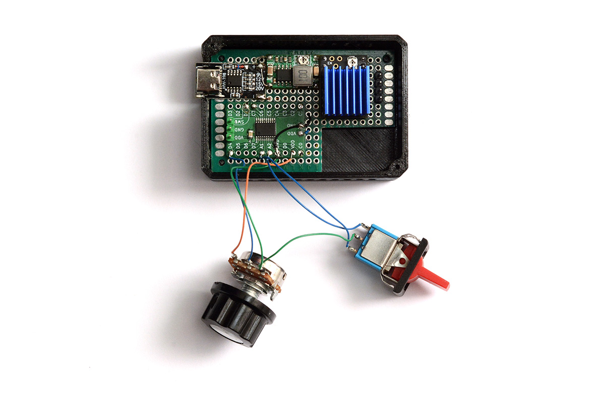
Studs supporting the circuit work fine. I was maybe a bit stingy only adding two screws to the lid. Couldn't even be bothered to do four symmetric screws. Then again, it's an honest signal of my frugality.
On the lid, I made the cutout for the switch a little loose, it's hard to guess how much the spring tabs need to be compressed. Probably should have done a test print. Instead of printing again I just glued a little shim in place, which makes it rock solid.
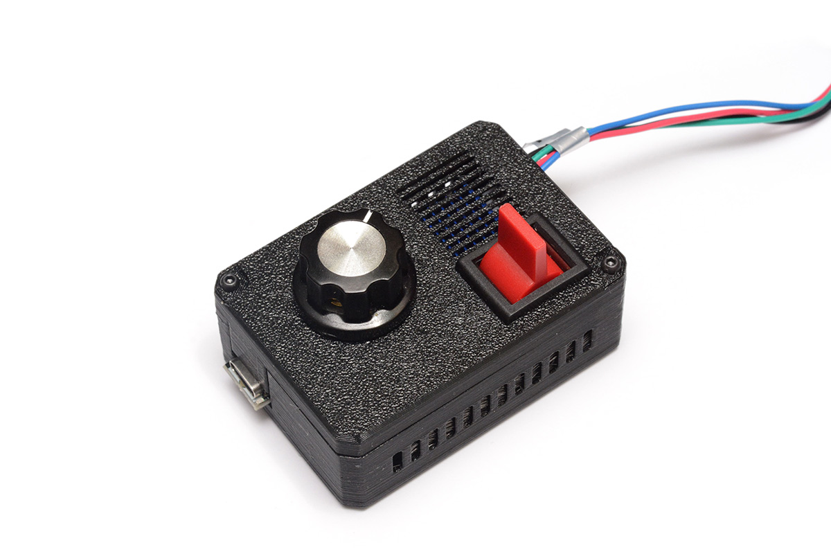
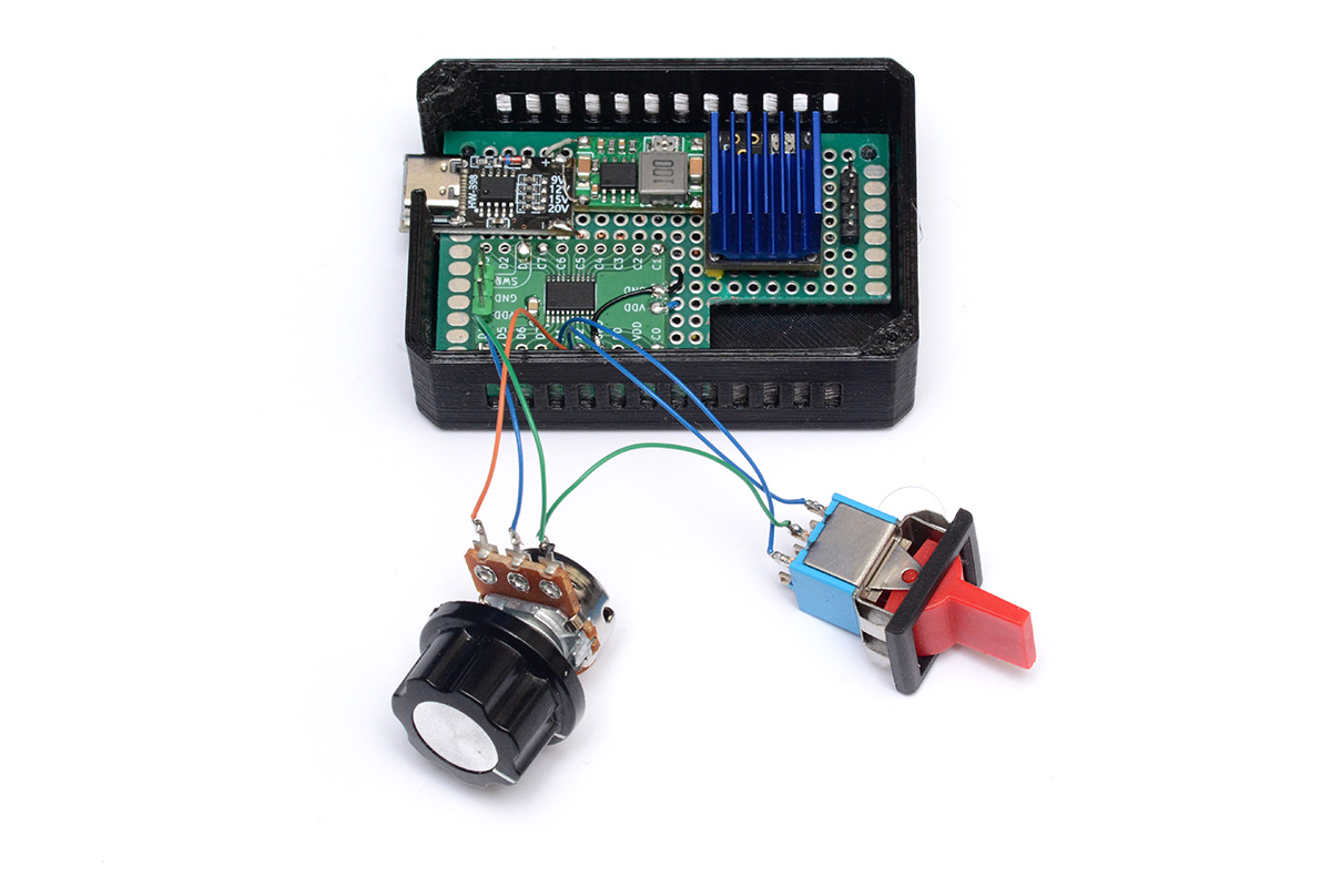
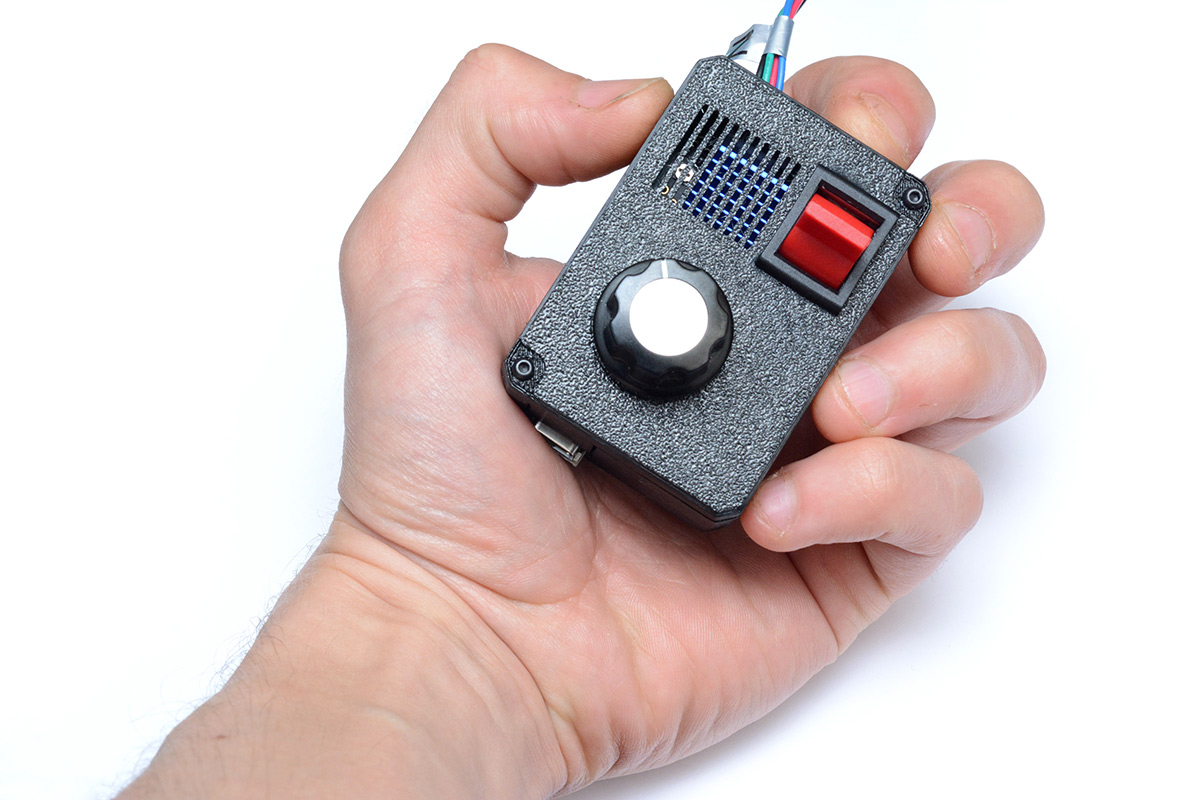
It's quite a pleasing little box! The grill and the knob make it look something like an old radio. Maybe we should have leaned into that and gone full art deco.
I suppose I could have made the air vents shaped like something, or spell out a word.
And now for the full assembly.
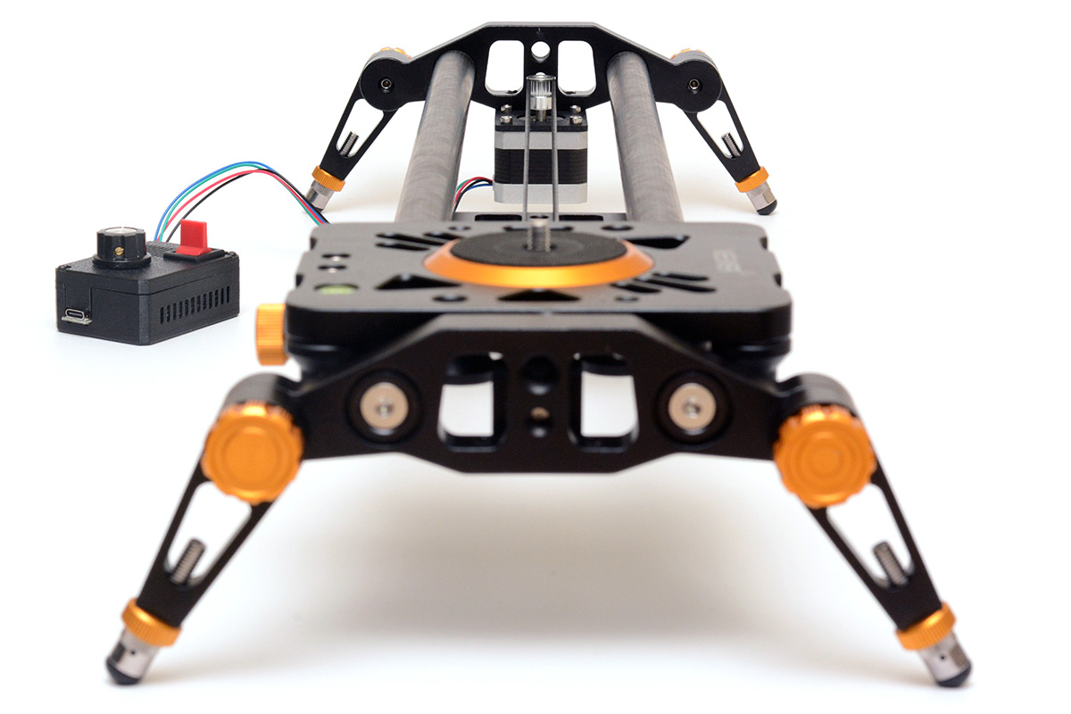
On the desk with the extended tripod head from my magpod:
With hindsight, I probably should have designed the case in a way that let you unplug the stepper cable. That'd let the device be used as a generic stepper controller, if ever that was needed. Some similar format steppers have cables that disconnect at both ends, which would be convenient.
It'd also be convenient if there was a mounting point on the case so we can stick it to the tripod, for when the slider is mounted that way. But I think a patch of velcro will suffice.
Potentially should have exposed the debug port of the CH32, so we can update the firmware without undoing screws. I can imagine eventually wanting some more complex behaviour, like ease-in and ease-out movements. But I'll worry about that when it comes to it.
Total parts cost for this conversion was about £20.
The donor "Neewer" manual slider is no longer made, it looks like they changed the design with their newer models ("newer neewers"), but on the odd chance someone out there has the exact same slider and wants to give it the same upgrade, the design files are here: beltclamp.stl, freepulley-bracket.stl, motormount.dxf.
Source code has been chucked in the usual places.
Cool. Look out for some smooth slides in my upcoming videos.