
Robot Slide Whistle Orchestrion
1 Apr 2024Progress: Complete
We all knew it was inevitable. Watch the following video to see it in action, or scroll down the page to read about how it was built and all the other ideas I had planned for it.
When I built the first robot slide whistle the plan was always to build a quartet of them, if time and budget had permitted. EMF 2022 was the perfect deadline to try and make it a reality. I submitted the idea as an installation, and got the thumbs up over a month before the event, but due to other commitments I couldn't actually start building this until two weeks before. I also gave a talk at the event (originally it was going to be two talks...) which meant I definitely over-committed myself. With the stress of trying to get the installation working, I ended up writing the talk on the morning I was supposed to give it, which was much less than ideal.
I spent most of the event worried about why it wasn't as in-tune as it was supposed to be. Unsurprisingly, trying to re-calibrate it, aha, in the field proved unsuccessful. My simple pitch-detection script couldn't really cope with the background noise.
Let's start with some of the ideas I had about what it could have been, with unlimited time, budget and enthusiasm.
Dreams of Bellows
A reminder once again that the airflow has to be controlled carefully. Blow too hard on the low notes and it jumps up a harmonic, blow too softly on the top notes and it won't sound. And even within the working range, the pitch depends on the flowrate.It makes the most sense to have one big source of air pressure with a separate regulator for each whistle. Perhaps a butterfly valve controlled by a servo right before each whistle would have worked, but I wasn't convinced that there wouldn't be interference between the whistles. If all of them are fully open, that's obviously going to deliver a different amount of air compared to just one of them being fully open.
I also thought about having four individual sets of bellows, either all driven by the same crankshaft or possibly independently driven. They would still need another regulating valve per whistle, but at least there shouldn't be interference between them.
I spent some time looking at how gas flow regulators work, and especially how organ reservoirs work. None of these are really designed to have adjustable regulation like we need.
I think if money and time were no object, I would have gone for multiple bellows per whistle. Behind each whistle, we could have had four or more little bellows in a radial pattern, driven from a crank in the centre like a radial engine.
Paper tape
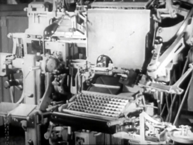
I have mentioned in the past my love of the Linotype machine and that 1960s video that explains how it works. After demonstrating the absurd complexity of the mechanical marvel that is the Linotype, it ends with a brief note that the machine is now being brought into the future via paper tape.
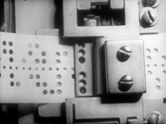
The paper tape is read via mechanical feelers, which then transmit the motion to the keyboard of the machine.
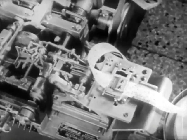
There exists a similar hot-metal typesetter called a Monotype which uses paper tape by design, but there's something just so ridiculous about a Linotype being converted to run on paper tape, with its keyboard typing itself like a player piano.
I think I had an obsession with punched cards and paper tape long before this, but it was such an amazing climax to an already amazing video that it had a long lasting effect on me. I think it's originally what made me discover the punched-card musicboxes that led to the MIDI musicbox.
So, an idea I may have mentioned more than once, is a punched-tape-to-MIDI converter. This could then be fed by hand, making the machine play music as you wind the handle, via the intermediary of MIDI.
A 7-bit paper tape could hold MIDI data directly, but this wouldn't give the right effect. To get to 31250kbps you would need to feed the tape incredibly fast. Using two or three bytes for each note-on message would make any polyphony totally out of sync if you wound it sedately.
A better approach would be to look at player piano rolls, where each hole corresponds to a note, and longer notes have longer holes. This still has some problems, while polyphony is possible our quartet of slide whistles are able to play the same note in unison, so there needs to be a way of notating that. It would also be much better if the four separate scores were individually decoded, so that one whistle can play a melody while another provides backing. Potentially we could have four separate sections to the roll, each one covering the 1½ octaves of one whistle.
Another option is to forget holes, and mark the paper with coloured stripes. These could potentially overlap and still be decodable by a colour sensor. I'm not sure which colours would be best, three is easy of course (RGB or CMY) but four would ideally need four evenly separated wavelengths. It might be fine to just print something out on a colour printer. That is another benefit, that printing out new music would be pretty easy. But I also liked the idea of plotting the music rolls, as the vinyl cutter can draw on an infinite canvas in one direction.
With the problems I had sourcing parts I sadly didn't have time to implement the tape reader, but it may yet happen in the future.
Choosing a fan motor, and issues of supply
All my idle dreaming about paper tape and bellows was justified because if I ran short on time I could always just build the original design again, or so I thought. It turns out almost all of the parts I used originally are no longer available.
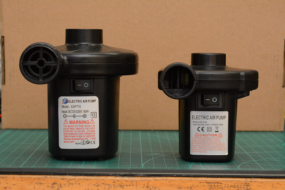
The listings showed what appeared to be an identical fan motor but what arrived was invariably something shrunken. The original motor was oversized, but that worked in my favour, running it at a slower speed reduced both the noise level and the risk of it overheating.
With increasing panic, I ordered a lot of different fan motors. It is very hard to find something that has both the right amount of pressure and flowrate. Compressors are high pressure but not nearly enough flow. I even tried out some extractor fans, which had flowrate but not nearly enough pressure. Here's a test using the traditional cardboard manifold:
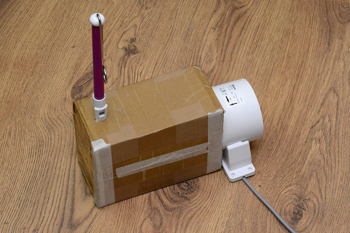
The above concoction couldn't sound anything more than the lowest notes.
The fan motors I eventually rolled with were quite small but of a slightly different design. Overall they seemed reasonably quiet, and without much leeway I simply had to make a decision before we got too close to the deadline.
I went through a similar panic with the whistles themselves.
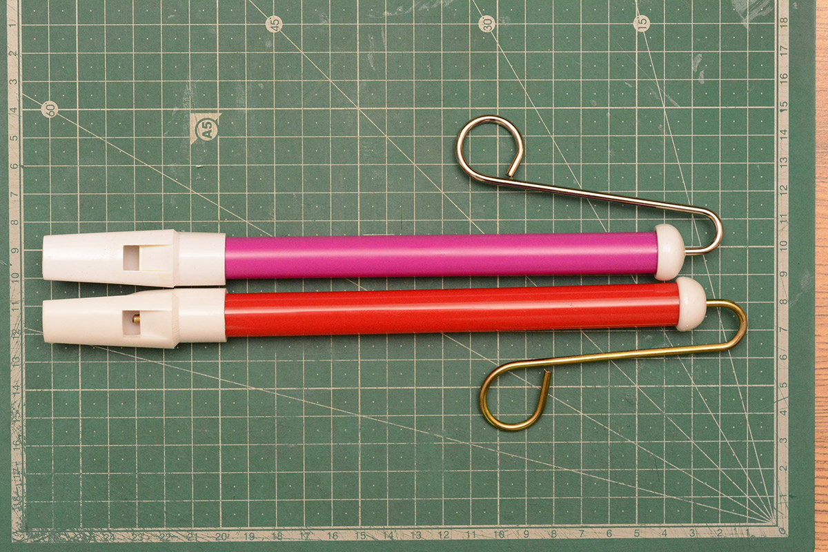
It's not just a size difference, there's a difference in quality too. Some of the whistles have a lot more stiction, almost as if the grease, or the plunger material, is incorrect. Once they've been worked back and forth a bit they're OK, but after sitting still for ten minutes it's like they glue themselves in place.
Making our own slide whistles from scratch does appeal, but for this creation I really wanted them to be off-the-shelf whistles. That's part of the appeal of the thing. If we build the whistles ourselves, I'd be wanting to extend the range of the quartet, and again this starts to run away from the idea of just four copies of the original creation.
With enough searching and madly buying what I could, I eventually found a supplier for a whistle that matched the original, and paid over £10 per whistle, which is insane for a tube of plastic. But, crisis averted.
The final important parts to source were the servomotors. By contacting the manufacturer I was able to buy six more of them. That is the advantage of having a part number.
Mockup
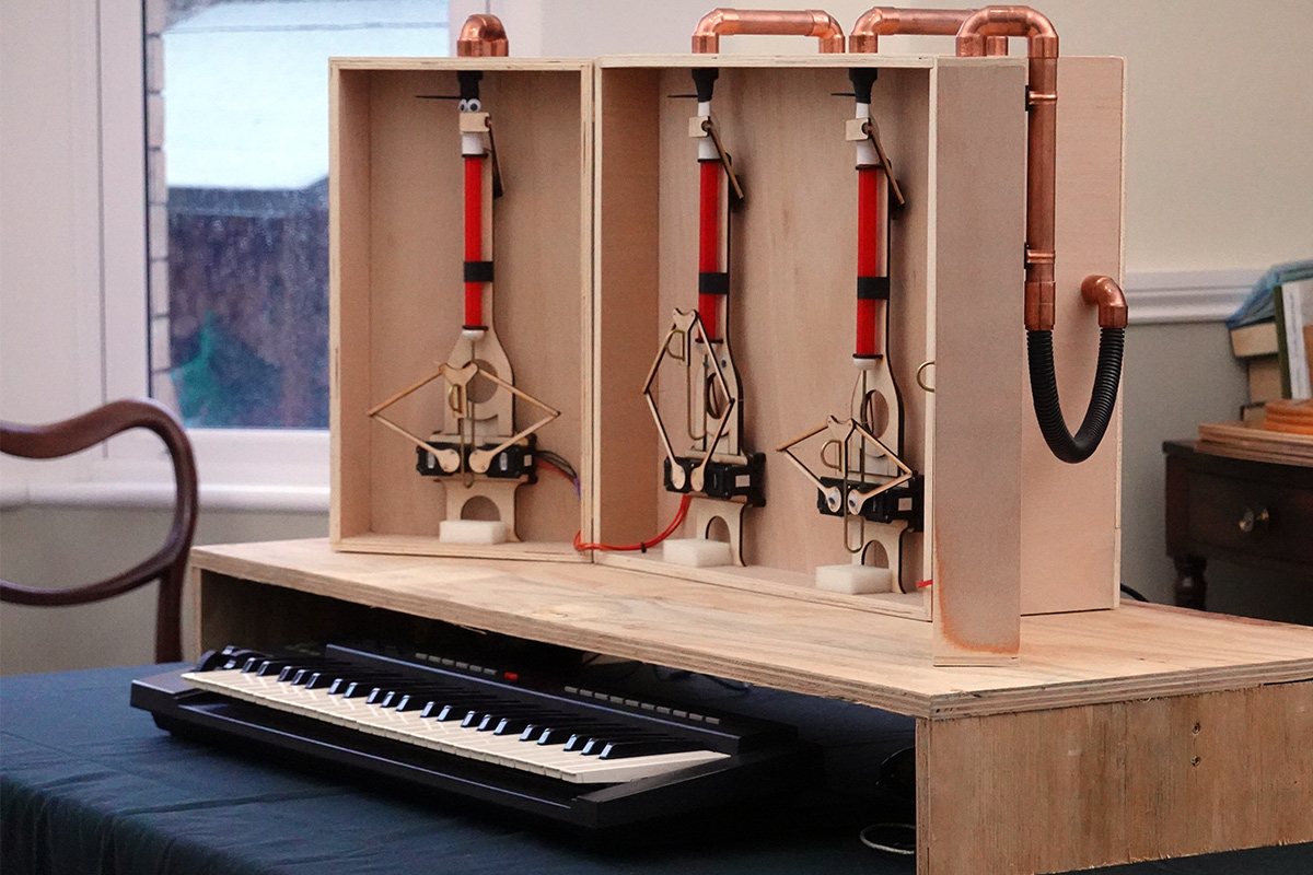
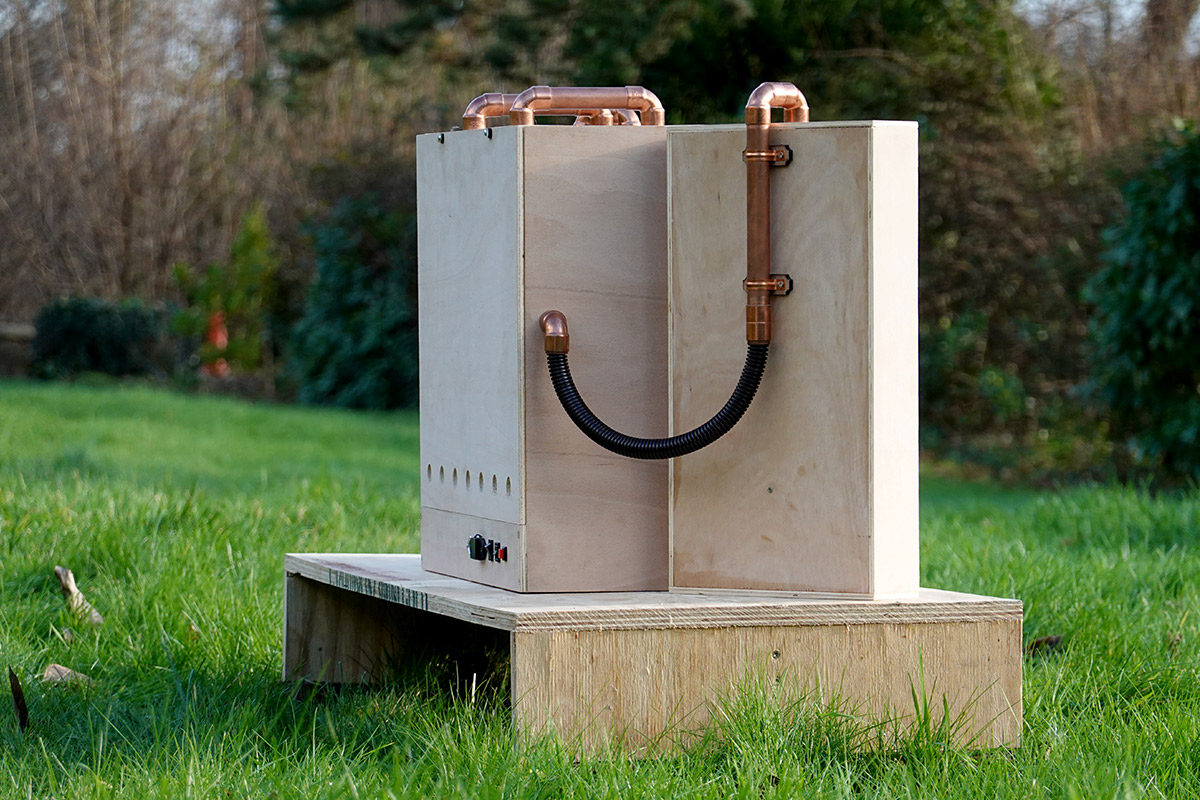
With the motors, whistles and servos secured, and the remaining days disappearing rather quickly, I had to come up with a plan.A lot of orchestrions have fine cabinets with lots of detail. Boy were we not going to have time to do anything like that. But I really liked the idea of a cabinet with an opening front, so the whistles can be put to sleep. As you've already seen, I settled on mounting two of the whistles in the moving doors.
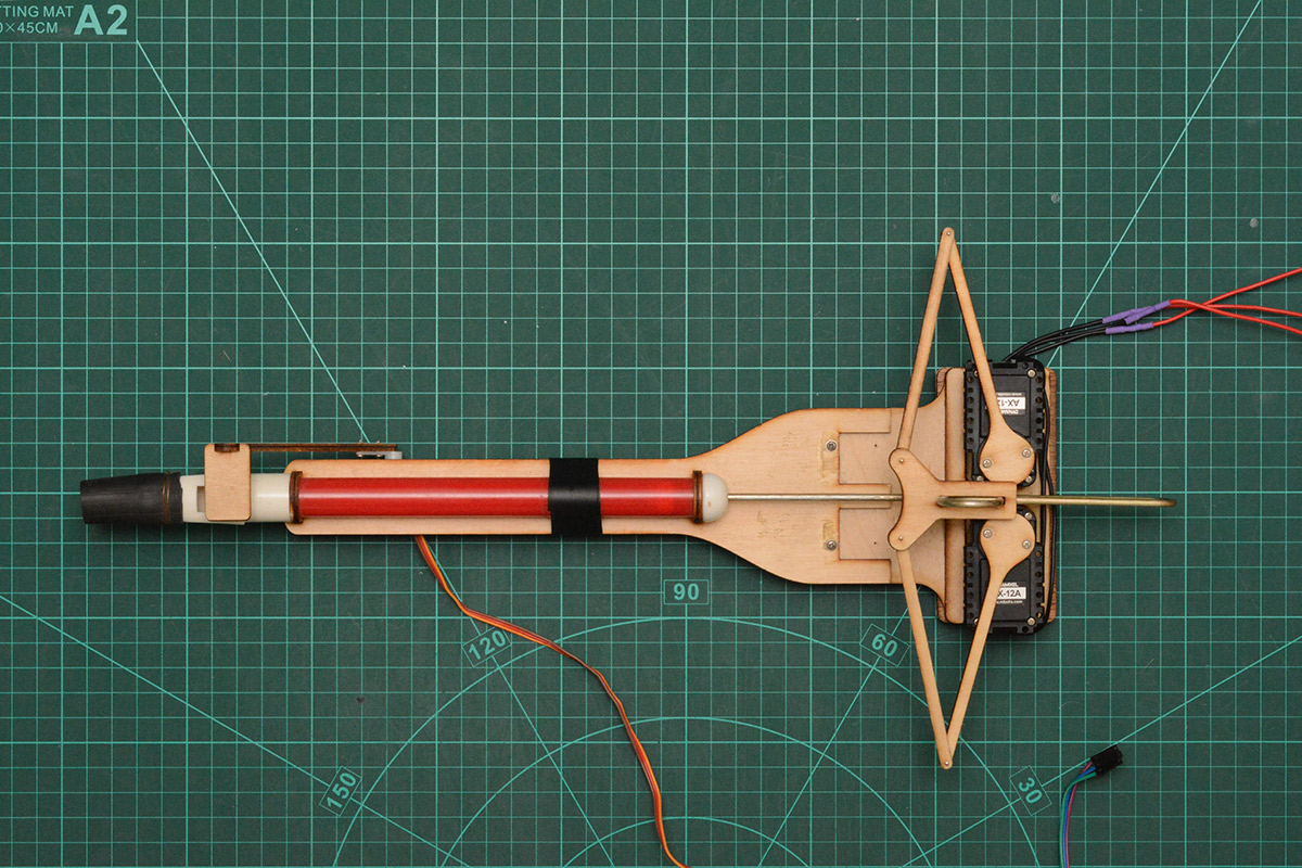
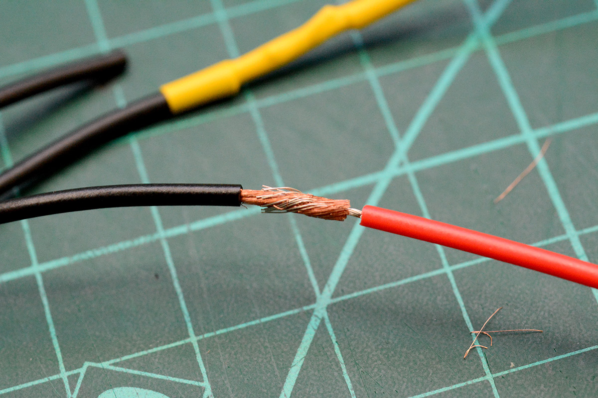
Taking a photo of the original whistle with my distortion-free macro lens, I was able to do a scale mockup in photoshop. The green cutting mat provides a reference grid, so long as the picture is taken directly from above. Once I was happy with the design, having checked the clearances for the moving parts, I could take measurements directly from the image.
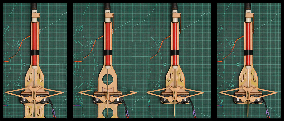
The original whistle did not have any kind of mounting. As you can see I played around with a few designs involving f-holes to give it some kind of Stradivarius cachet, but the simpler design was more visually pleasing.
I sent the following sketch to the EMF organisers:
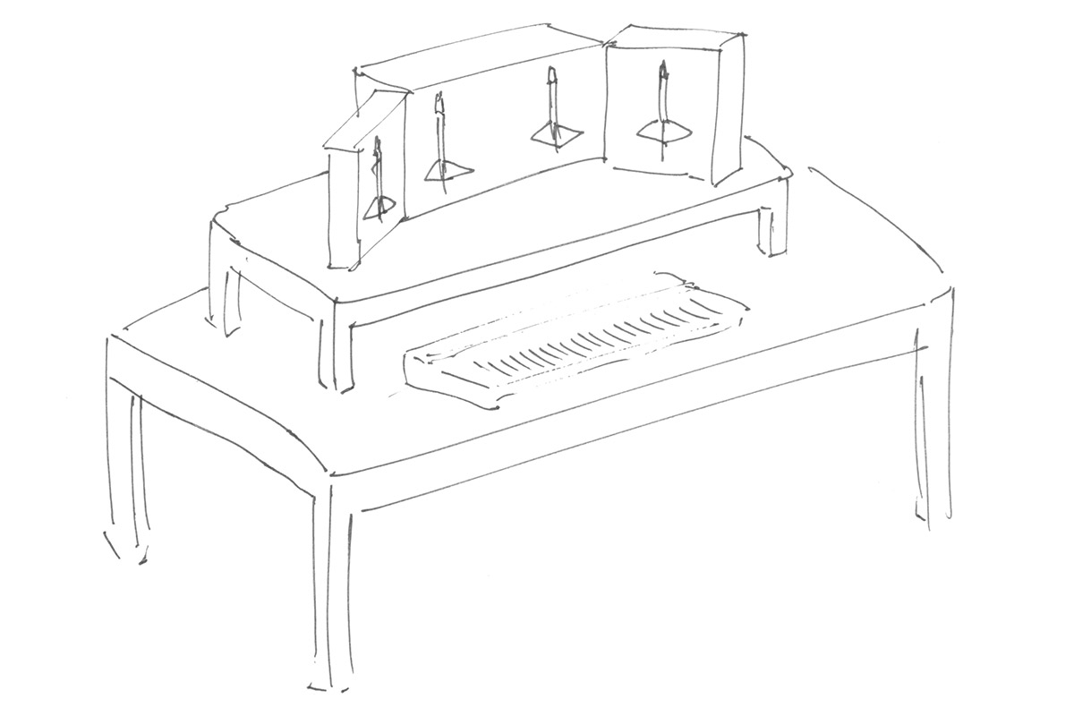
In retrospect, it's a pretty accurate picture of what I ended up building.
Building the enclosure
For the amount of woodworking I do, I can't justify having a table saw or table router in my house. I mean I don't even have room for a milling machine or a decent lathe. But at the times these tools, nothing else will do! Luckily, at the time of this project, the hackspace still existed and was supplied with ample woodworking tools.
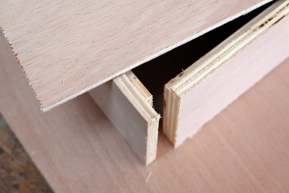
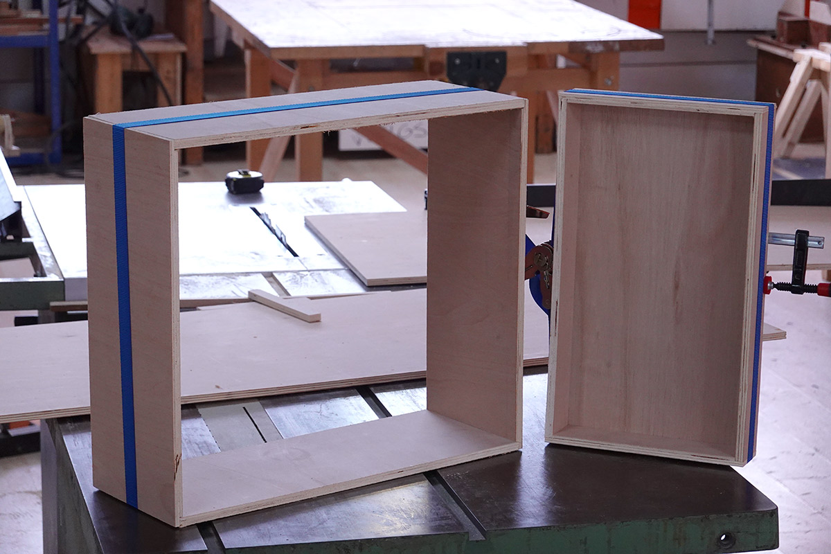
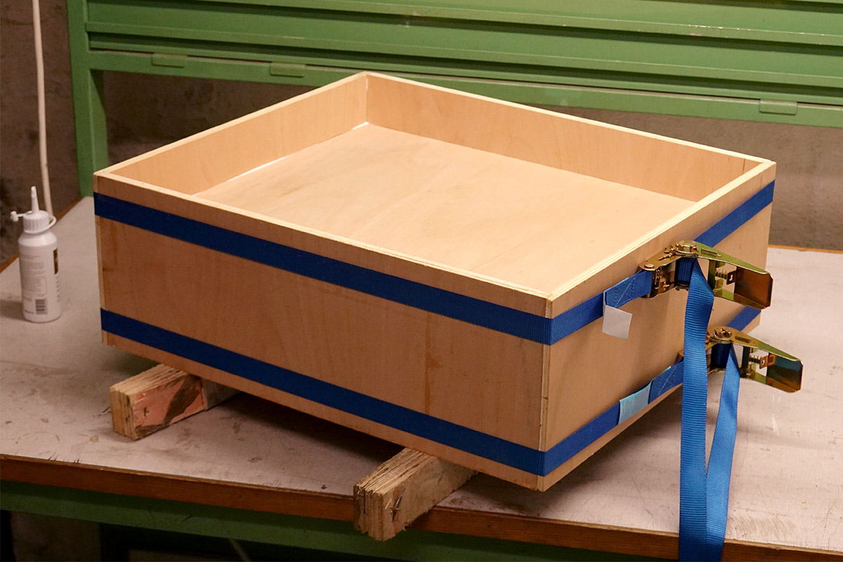
I chopped up various bits of plywood and added rebates (rabbets if you're American) with the table router. A ratchet strap holds a test fit of one door together.
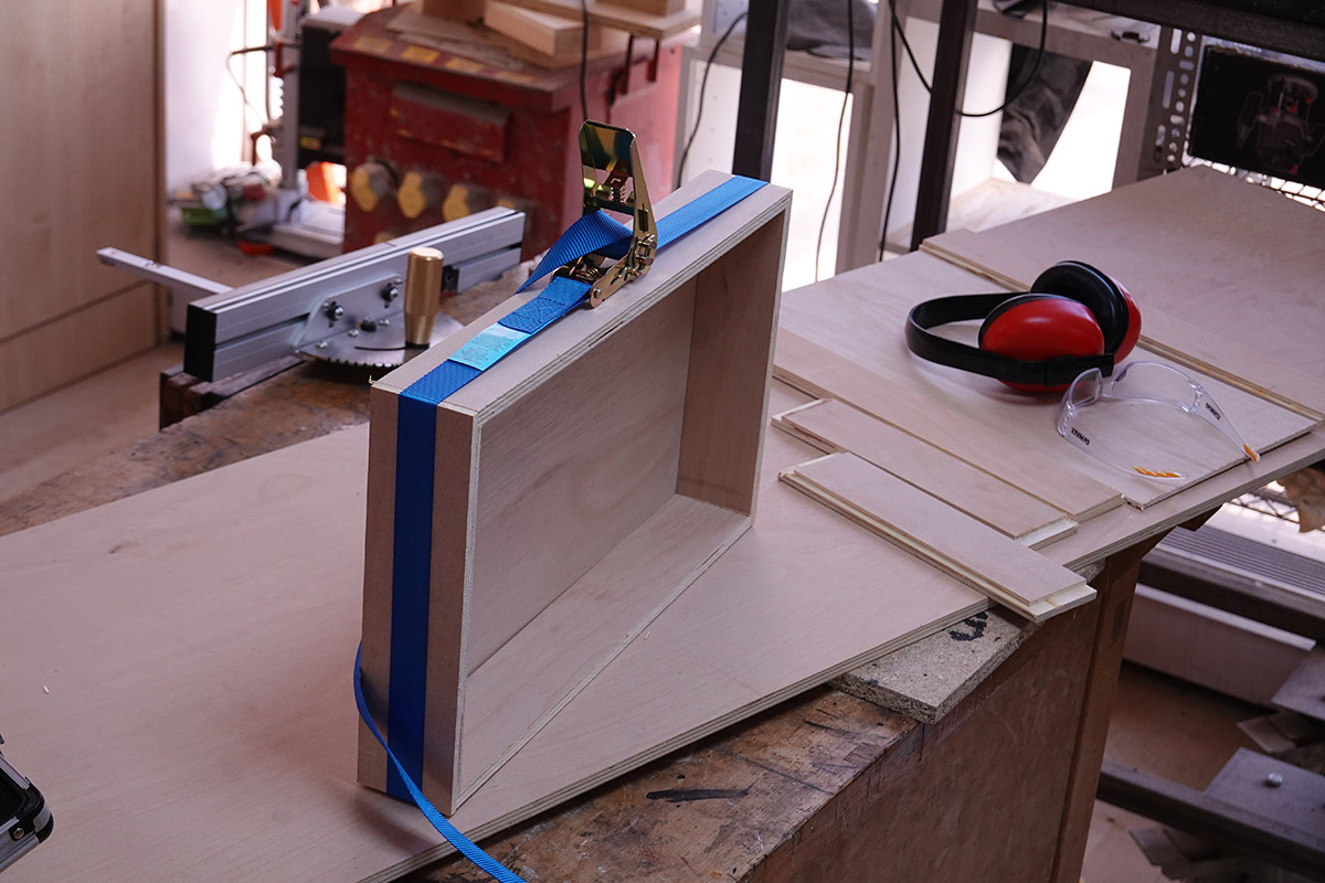
It is sometimes helpful to double check the thing is going to fit. I never really had a doubt, but it's good to know the arms can go through the range of motions without colliding with anything.
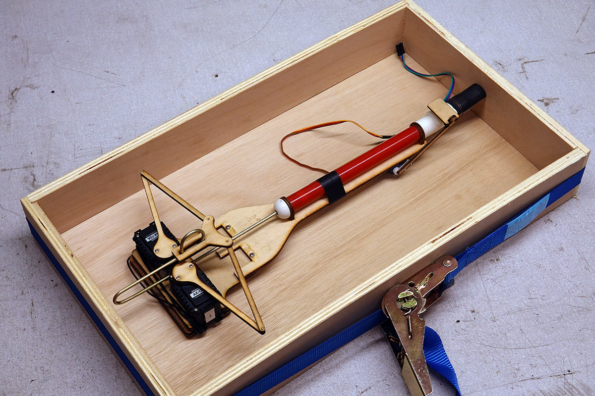
The thickness of the main body had to be calculated carefully. I needed enough space for the whistles (with the doors closed), then the fan motors and power supply and everything else in the back.
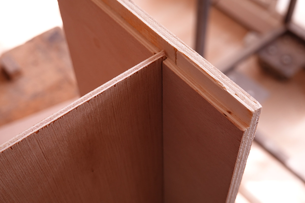
With the smaller table saw, I created a dado (slot) all the way around the inside, so the dividing wall could be encapsulated.
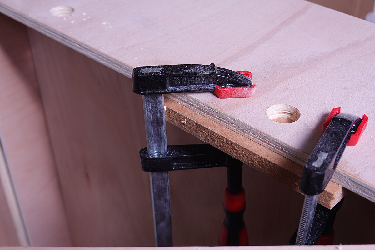
With that, it was time for the first glue-up, which was mostly limited by how many clamps I own.
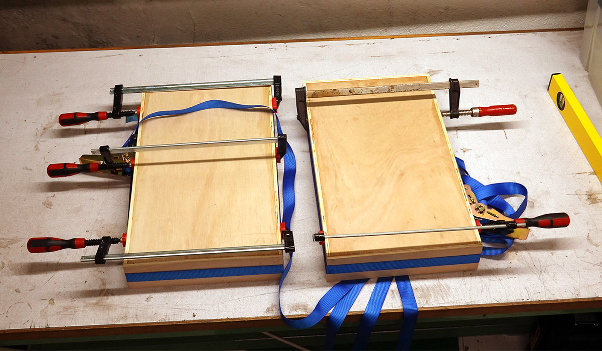
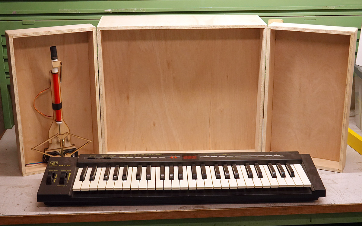
Once dry, I was able to attempt another mockup.
More gluing, now the ratchet straps were free.
The only part remaining was the back cover. I had big plans for that, but it could wait – time to build the circuit.
Circuit
An ATmega238p was used for the first slide whistle, with the code written in assembly. A beefier chip was needed to run four whistles at once, and with the chip shortage in full force about the only board I could get at a non-inflated price was the "black pill" STM32F401 (probably clone). The Raspberry Pi Pico had been released, but I hadn't tried one yet and switching to an unfamiliar architecture always comes with a risk. It turns out the Pico is very easy to use, but I didn't know that yet.The original circuit also used the very simple motor drive arrangement of a single TIP120 darlington transistor. This is pretty inefficient but means you don't have to worry about level shifting. Here I figured doing it "properly" with mosfets would be sensible.
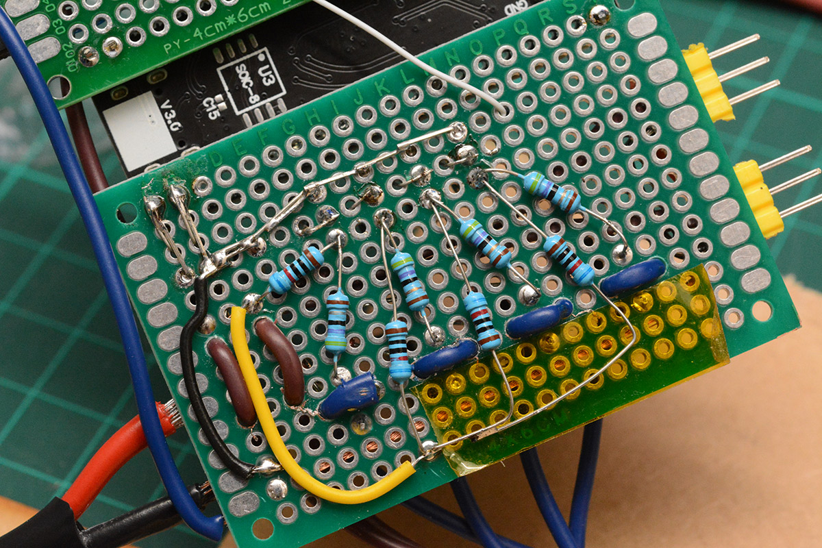
To drive a mosfet from a 3.3V signal requires level shifting. In fact, there is a whole category of chip known as a mosfet driver, designed to switch them quickly. The gate is voltage controlled, but has a certain amount of capacitance, so in order to quickly switch the device you need to momentarily provide a very high current.
But simple level shifting is easy with a single BJT and a resistor.
I forgot one of the critical things I learned from building the first one, and rediscovered that the PWM frequency driving the fan motors causes electro-acoustic effects. If you drive the motors at 1kHz, you get a loud 1kHz whine coming out of them; a disaster for a musical instrument.
So the switching frequency needs to be at least 20kHz to avoid being heard, and suddenly we're trying to switch the mosfets at a significant speed. To overcome the gate capacitance in this arrangement means increasing the strength of the pullup resistors (i.e. reducing their resistance). But that means they'll always be burning power, and the heat problems we were trying to solve originally are suddenly back.
This is one of those situations where starting over and doing it properly would be faster, but in the heat of the moment it's easy to feel like just one more bodge will hold the thing together. The worst bit about the way I wired it is that if the GPIO tristate, the mosfets default to "on" and all the motors run at full speed. Even for the highest notes, the motors wouldn't normally go above 40% speed, so full speed sends them all into a maddening, piercing scream several octaves higher than usual.
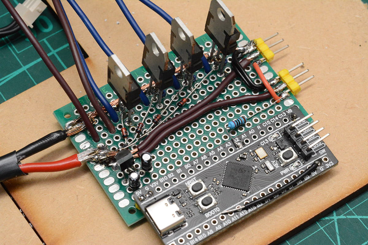
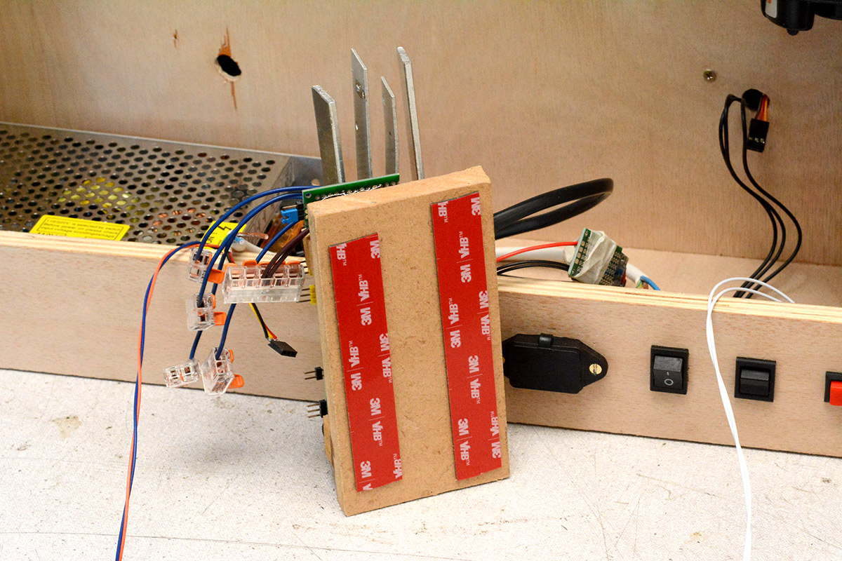
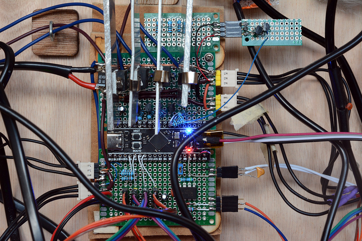
I continued to add more boards and more bodges.
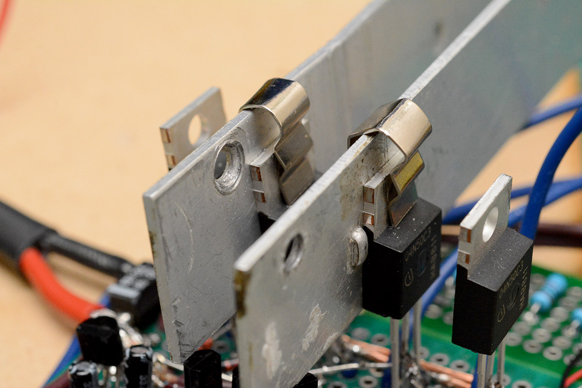
The metal clips attaching the heatsinks are bent out of the 12V lighter adapters that came with the fan motors. I mounted the construction to some MDF so it can be fitted inside the case.
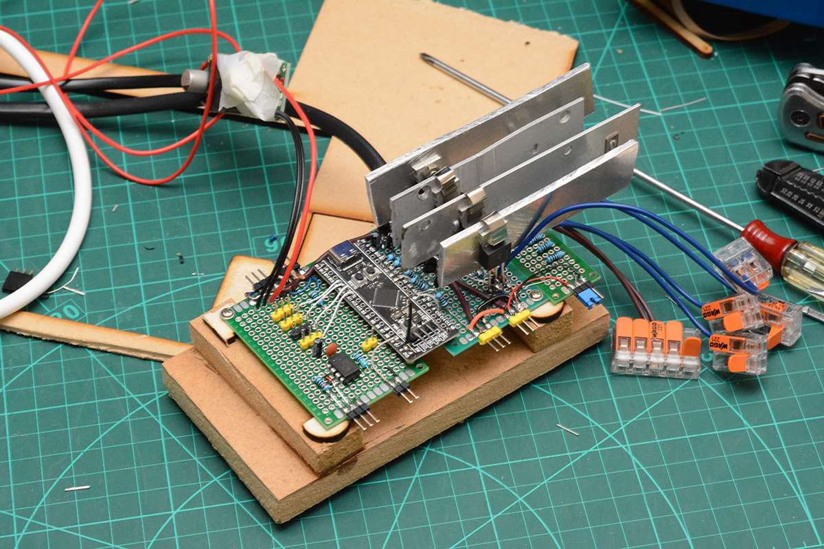
On right is the extended pullup board, under the heatsinks there are more transistors. The blue jumper on the far right is the cutout to the pullup resistors, this then got initially routed to a switch on the case, to let me disable the fan motors. I ultimately replaced that with another board with a couple more transistors that finally gave software control over the pullup voltage.
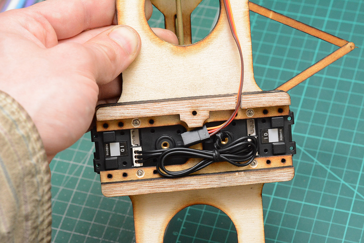
On the left is the optoisolator for MIDI input and connectors for each of the valve servos, whereas the Dynamixel servos connect to the yellow header pins near the mosfets. They use a half-duplex communication bus at 1MBaud. Each servo is manually programmed with an ID and then packets can be sent addressed to the servo in question.
The small servos controlling the valves are driven in the conventional way with a slow PWM signal. I used metal gear servos this time and was shocked (shocked!) by what an improvement they give.
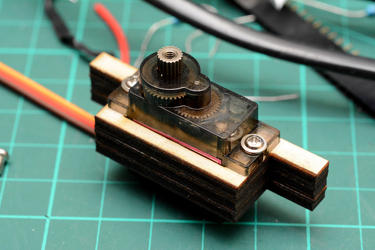
The little 9g servo I used on the original whistle caused me no end of problems, with its analog feedback getting confused by the fluctuating power supply. The MG90S metal-gear servo in the same form factor costs about five* times as much, but has a digital control board and is comparatively immune to power supply noise. I'm tempted to rebuild my musicbox with 30 of them, though it would be expensive!
(*ok fine – they're £5 each instead of £1 each)
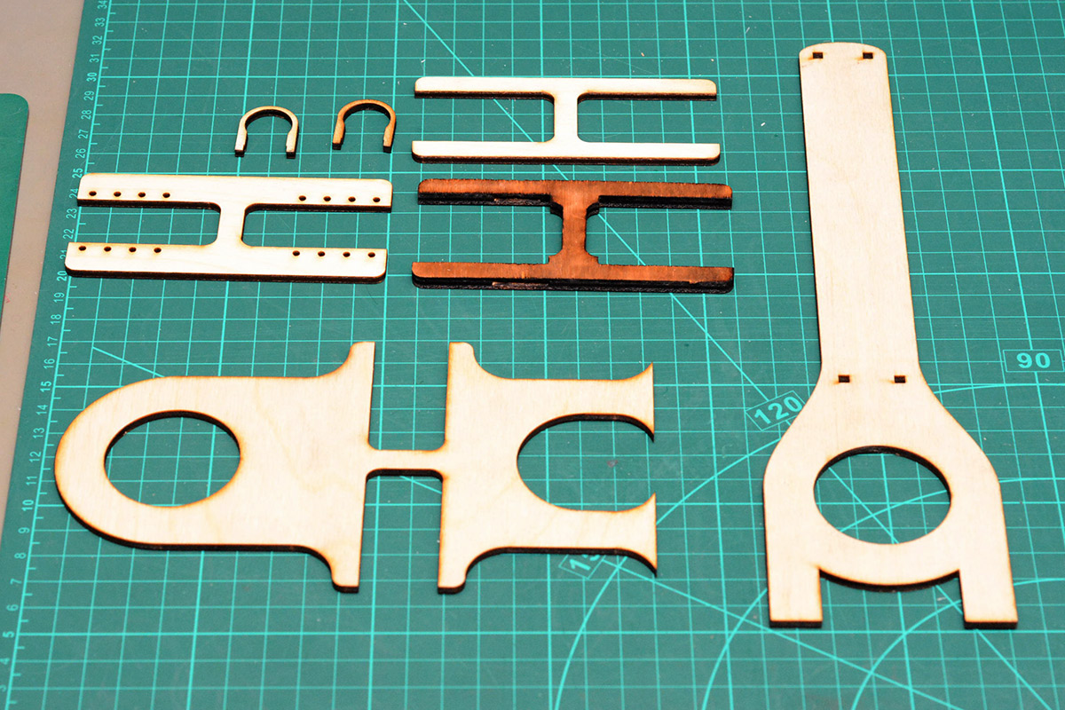
Laser cutting
Only a few days before the event, I began the mammoth task of laser cutting all the parts on my K40. I had a brief scare when some of the plywood I'd bought turned out to be of a different grade to the rest, with a much lower density. This means it cuts very quickly, but made me worried the arms wouldn't be strong enough. I desperately ordered more plywood from several different suppliers. At least it will all get used eventually.
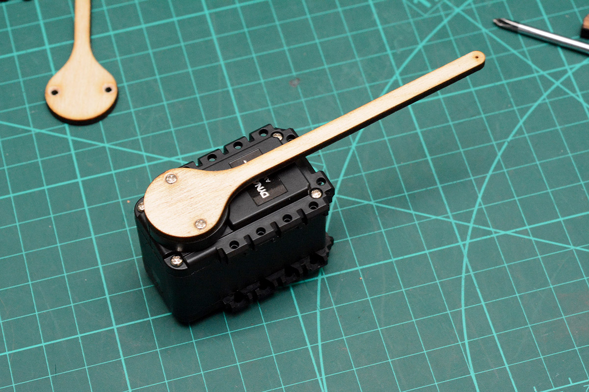
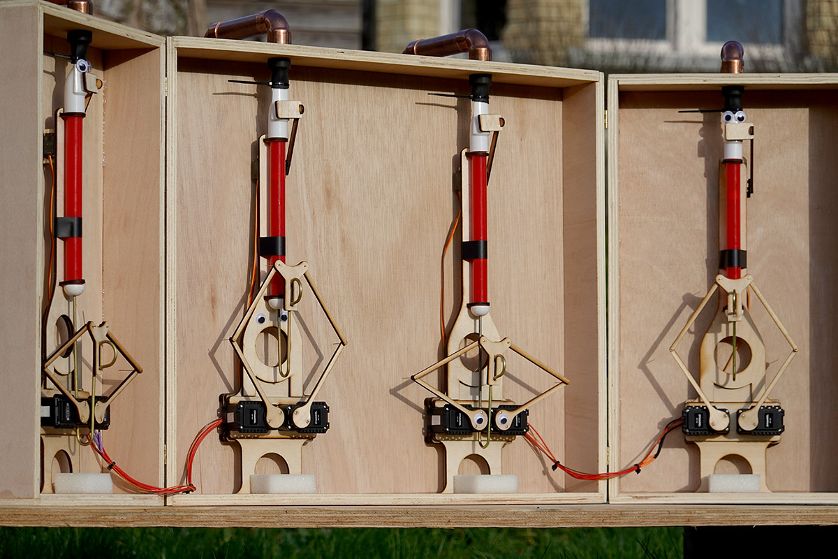
The various layers are superglued together. The pivot points are dressmaker's pins through slightly undersized holes.
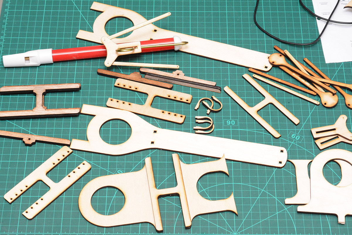
The big servos slot into the frame and are held very securely, bolts are added only to stop them sliding out.
Ducts
Do your ducts seem old-fashioned, out-of-date?Plumbing the air supply was yet another unexpected headache. I found it quite hard to get hold of ducting or hose that was compliant enough to let the doors open. Most of the materials I used were insufficiently flexible. I ended up using some electrical conduit that was about the right diameter but still too stiff, and simply disconnecting it when the doors are closed.
Making these decisions, such as where to drill through the case, induced a lot of anxiety as any mistakes are permanent. We don't have enough time to build another case.
Before drilling the holes, I clamped some MDF backing to stop it tearing out, then freehanded it with a 22mm spade bit.
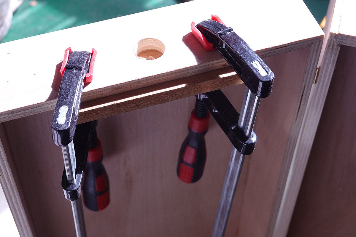
It's easier than it looks to get the hole clean, if the spade bit isn't held perpendicular it becomes very obvious, so it's easy to correct as you're drilling.
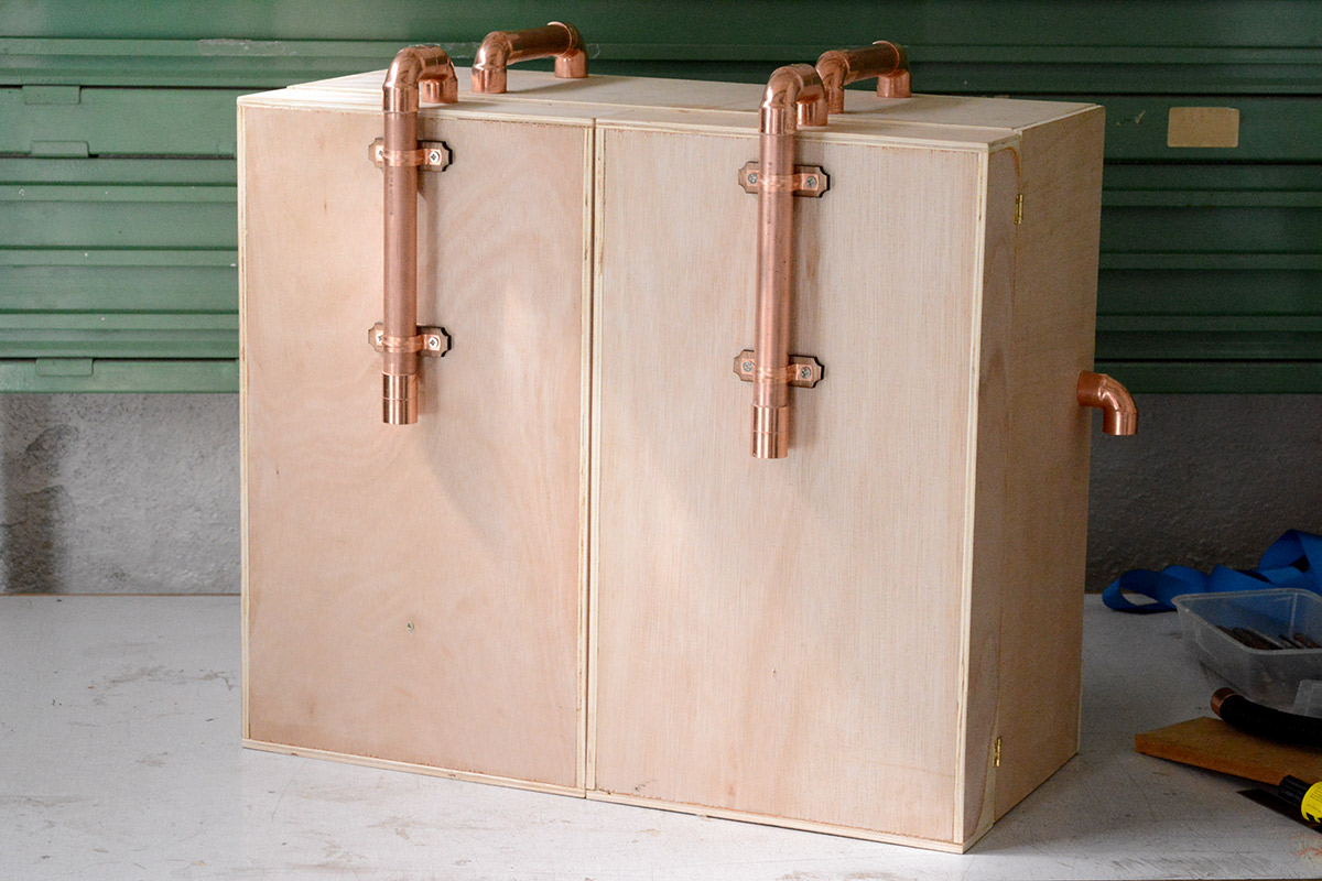
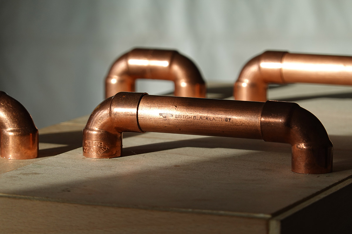
22mm copper pipe was used for the rigid connections. This pipe was ripped out of an old hot water system from the 1980s. I sanded the outside so it looks like fresh clean copper, but the inside is comically corroded.
Some new copper corner connections were sourced.
Naturally, I was going to solder these joints together, but I was so short of time at this point that I couldn't justify it. Because of the plywood, it wouldn't be possible to solder it in place, so we'd need to hold it in a jig. Instead, I just smeared each join in glue and shoved it together. It doesn't need to be watertight.
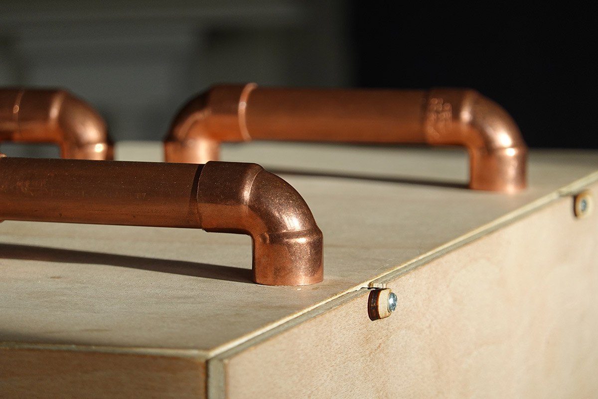
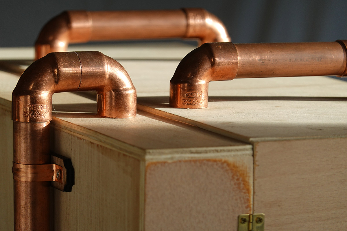
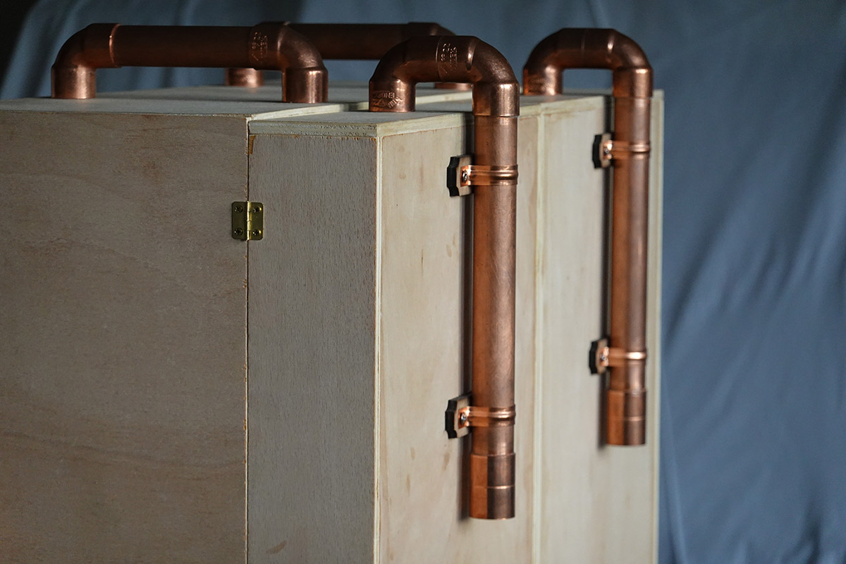
To attach the pipework we needed some brackets. Ordinary pipe clips would do but the geometry wouldn't allow them to be flush to the case (unless we sliced some of the corner coupling away). I also wasn't keen on screwing into the thin plywood that makes up the door panel. Instead I laser-cut some supporting parts (with little decorative cutouts) to which we can screw the pipe clips.
I then used a grinder to remove the backs of the screws, and used superglue to attach the brackets to the plywood case.
The removed points of some of the screws are visible in the picture above just to the right of pipes.
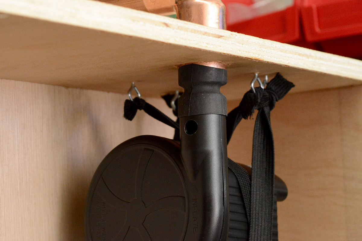
The fan motors were now mounted into the case, using bits of bicycle innertube as flexible couplings, and elastic to support the fans themselves. This provides the most decoupling from the frame possible, for noise reasons.
Also visible are the two holes I made for bringing the wiring through from the front.
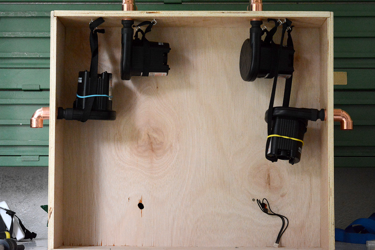
I had a weird moment where I ran out of bicycle innertube. Which sounds ridiculous because in the past I've thrown away so much of the stuff, but here I seemed to only have about six inches left in stock. I considered going out and buying a brand new innertube to chop into bits, but the very thought of doing so gave me pins and needles.
I very carefully metered out the remaining innertube to avoid such a ludicrous eventuality.
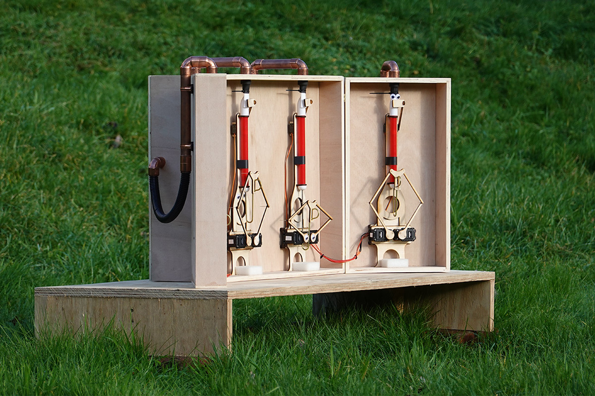
With the hinges mounted and the doors in place, the plumbing completed, this mad creation is finally coming together.
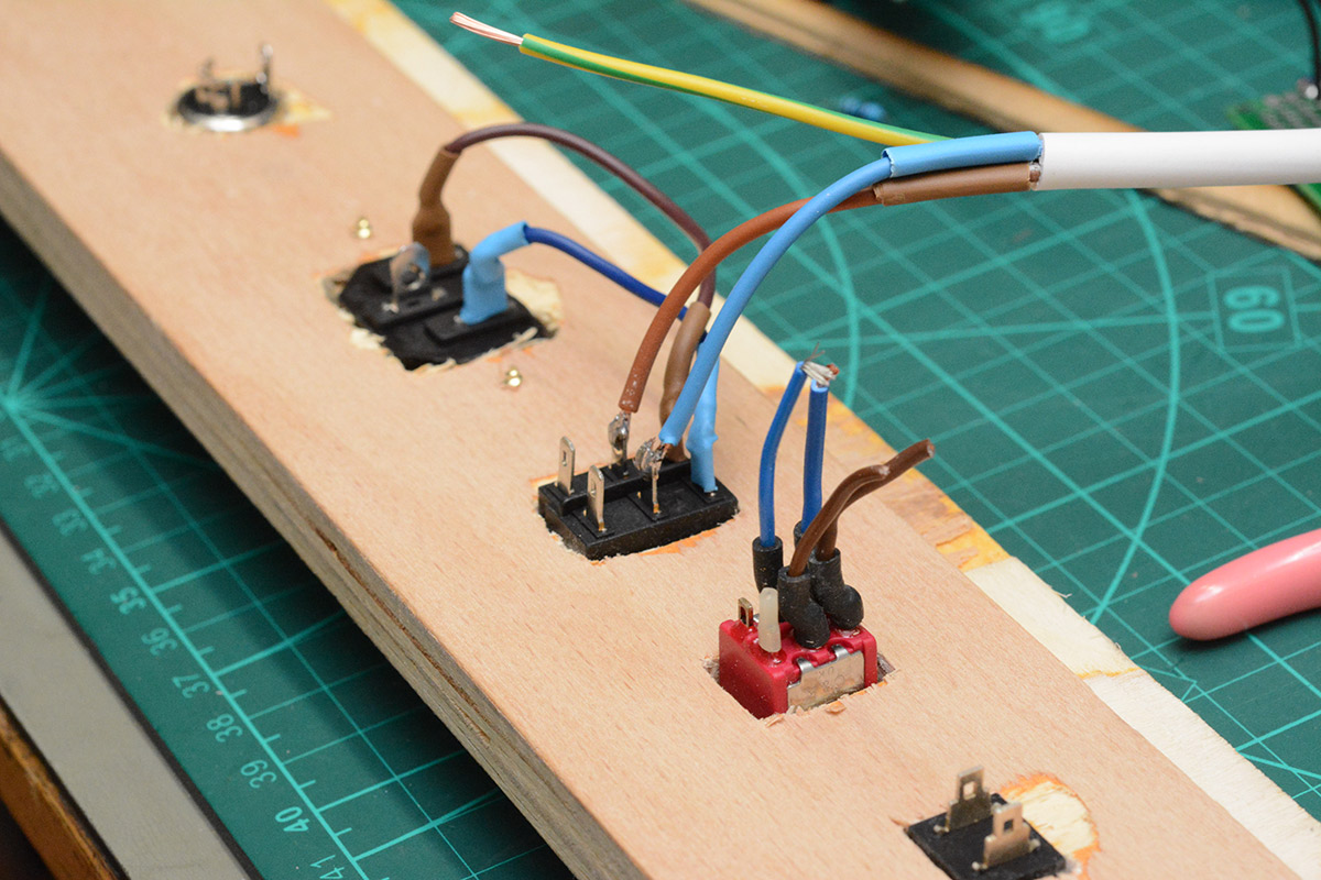
Wiring up
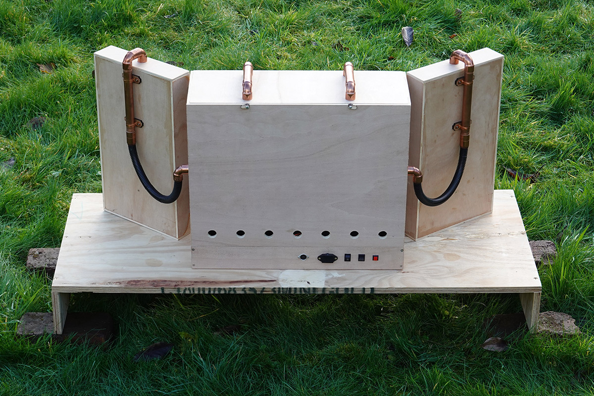
I hadn't yet created a back panel for the thing. I had some great ideas about what I wanted to do here, none of which came to fruition. The back needs to host not just the switches and connections, but also the air intake. I had this idea to create some kumiko-style wooden grills to make a feature out of it.Sensibly leaving the decorative grills until last, I made a small strip along the bottom to mount the connections for power and MIDI and the switches.
This panel could then be permanently mounted while I pondered what to make for the removable back.
The circuit board and its MDF carrier were given the fancy 3M tape treatment. Visible in the above picture are the main 12V power supply and a supplemental buck regulator, that delivers 7V for the small servos. The Dynamixels are happy to run from 12V. They come with very nice, super flexible cables which sadly weren't long enough. I had to extend these with regular wires, performing an axial splice (soldered and heatshrinked).
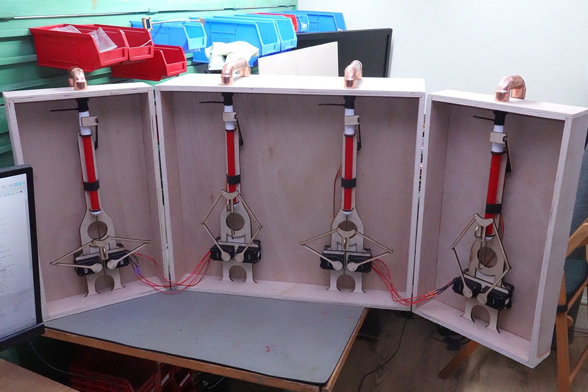
Skipping a whole load of tedious assembly, about a day before the event I reached the point of four assembled whistles in a box.
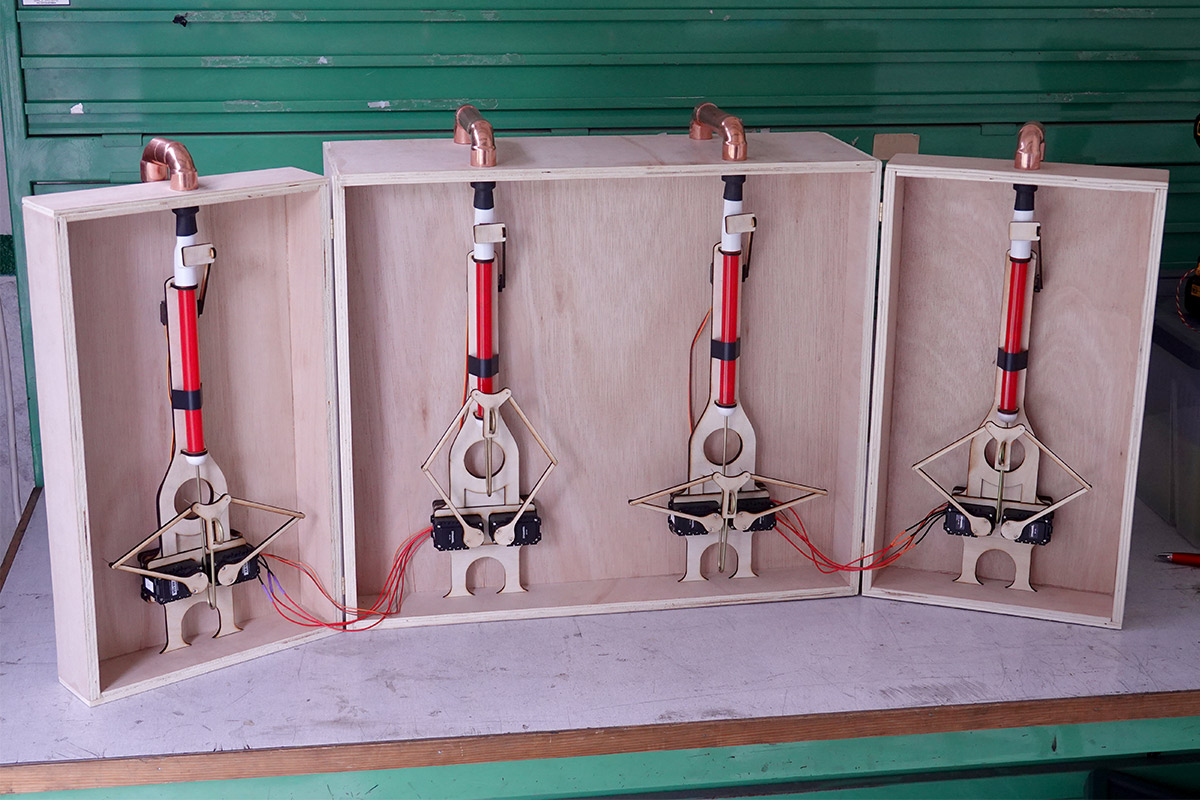
Crikey. This wasn't yet functional, the innertube needs to be sealed to each whistle at the top, and of course we need to write all the software for it.
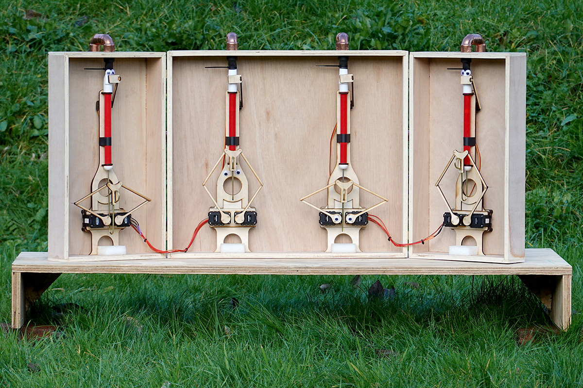
The alternating up-down-up-down positions are needed for the doors to close. This is by design, to keep the depth to a minimum. The red button on the back is intended as a "home" button, that sets the whistles to this position and allows you to close the box. It also serves as a MIDI panic button.
Software
I wrote the software using STM32CubeIDE. Quite frankly it's a piece of shit. But I needed to get this done fast.
Timer configuration on STM32 chips is notoriously complex versatile, with lots of timers having lots of channels and lots of modes. Here we need to generate four PWM signals for the motors, and four PWM signals for the valve servos. TIM1 and TIM3 both offer four channels of PWM output.
We need two UARTs, one for the MIDI input and one for the Dynamixel output. While the Dynamixel bus is bidirectional I wired it as output-only, I'm not going to be querying anything back from them. As with the first whistle, I took advantage of the big contrast in bitrates. With the output being at 1Mbps we can send an entire 8-byte packet within the time frame of a single byte received at 31250bps. This makes things much simpler: we can run our MIDI detection as a byte-wise state machine, and send whole packets out in blocking mode without worrying about missing the next byte in.
To be fair, sending packets with DMA isn't that difficult to set up, but any corners we can safely cut are a bonus.
Before implementing MIDI I implemented the calibration/test mode. This just accepts raw numbers that should be forwarded to the servos and fan motors. The calibration script from the previous project was adapted and updated. As before, we first experimentally establish the range of flowrates for a good tone at different slider positions, then perform a sweep through each slider position measuring the pitch out. Finally we invert the table, to get a lookup between note number and slider + fan motor values.
The first and most important problem encountered is that the fan motors I settled on are a lot worse than before. If I send one a duty cycle of 20%, and the motor is currently off, it won't start spinning – that's not enough power to get past the stiction. If I send it full power for half a second and then drop to 20%, it'll end up spinning too fast for the lowest notes. But the real problem is that if it's been on for a few minutes, setting it to 20% will give a different flowrate again, presumably because the grease inside has warmed up and changed viscosity.
The only reliable solution to this is mounting an encoder to each fan motor and using a PID loop to control them. With one day until the event, however, that wasn't going to happen, so my bodge involved tracking the previous values sent to the PWM output, and if there's a sudden increase in required speed (or start up from zero) it momentarily sends a pulse of full power, then drops to the target amount. This, at least, is enough to break the stiction and ensure the fan motors are spinning.
Also, I boldly drilled holes in the fan motor outlets. At the risk of ruining everything, this pushed each fan motor's normal operating speed up a bit, which (in theory) should reduce the effect of (linear/static) friction.
Another problem I encountered is the serial data for the Dynamixel servos could be unreliable. I attributed this to noise/reflections on the cables, and played around with different values of source termination. It's not clear what kind of terminating resistors are on board the servos. One solution to this would be to use a buffer chip to duplicate the signal and send to each servo (or pair of servos) separately. They don't really need to be on the same bus.
The messages on the bus are all CRC checked, so a corrupted message shouldn't be fatal, just dropped. The message format allows you to address multiple servos in the same packet, so I send each pair together, with the idea being that if the message is missed at least both servos will miss it, and not fight each other. In practice, this didn't always happen. There are occasional moments (including at least one in the video) where the servo arms jump to different values, presumably because one of them had a bad CRC but not the other.
It would be tempting to adjust the design of the servo arm to have gear teeth at the base, meaning that if ever the servos jump to different values, they fight each other directly instead of via the spindly arms that could break.
One software solution would be to re-send the packets a couple of times just in case. I did try this, but then hit another snag. Under some circumstances, this would miss MIDI messages. As mentioned I send the packets out in blocking mode, and doing this repeatedly can take longer than one byte at 31250bps. There's only one situation that caused this, which is polyphonic pitch bend.
Naturally the whistles support pitch bend. But in auto-polyphonic mode, we can bend all of the whistles at the same time, which means addressing all eight servos at once. That means the total packet length, if sent in duplicate, can exceed our allotted time. At the event, I played around with this a bit but as I calmly reflect on the process, there are a number of simple solutions: use DMA or interrupts to transmit in non-blocking fashion, retransmit many times if we need to, clean up the wiring with buffer chips so the signal integrity is better.
I should explain the auto-polyphonic mode. The first four MIDI channels control each whistle individually, but channel 5 is auto-polyphonic. This lets a keyboard player use all the whistles at once. The logic is fairly simple, we assign a cost value to each whistle, based on how far it is from the desired note and whether it's currently in use. The whistle with the lowest cost is chosen for that note. Some careful management of which notes are currently playing completes the logic.
First power-up
All that, and there finally came a moment where I loaded up a MIDI file and pressed play.The file I chose was All Star.
The fan motors were slow to spin up, the whistles started sliding well before we heard notes. Gradually there came a crescendo, as the room filled with wonder, the whistles piped up as they tried not to be drowned out by our maniacal laughter, their un-calibrated jerking discordant, but through it all, that melody could just be made out:
"...body once told me the world is gonna roll me, I ain't the sharpest tool in the shed..."
I quickly assembled the back panel. No time for kumiko. Drilled a series of holes with the spade bit instead. One thing I did commit the time to doing is creating a latch to make removing the back as painless as possible, I just knew it was going to be removed a lot.
They're laser-cut ovals loosely fitted with a bolt. The back panel has U-shaped cutouts.
The event
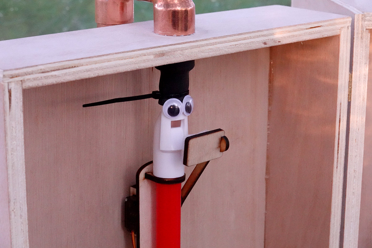
I was so busy worrying about it being in tune that I didn't take any pictures at the event, but a few people recorded it on their phones.
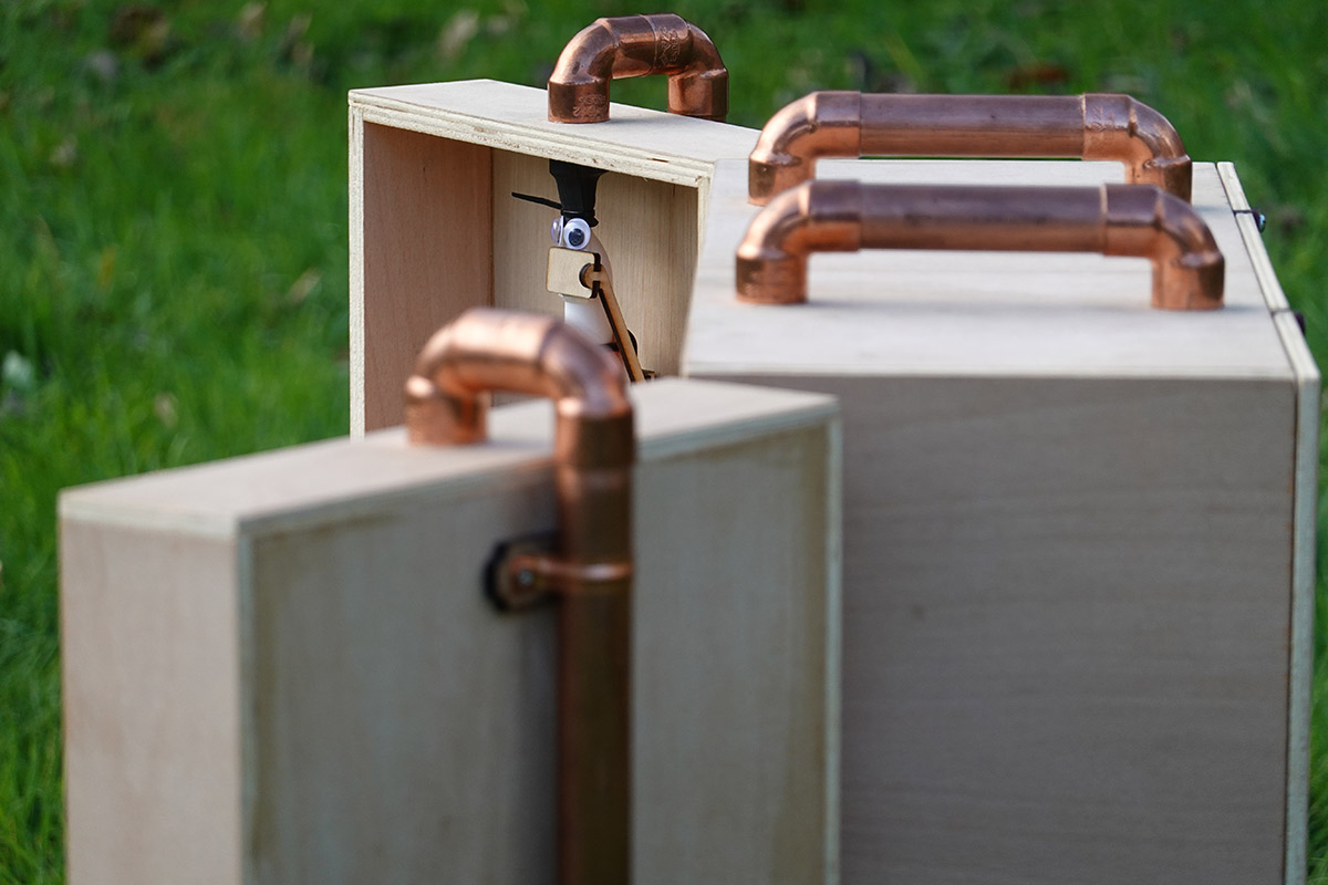
It wasn't long before someone added googly eyes to it.
One slight regret is that the dome we installed it in was smaller than I expected. While it was next door to the lounge area, it wasn't as well advertised as it could have been and not everyone saw it. A friend captured this image of me fiddling with it during the initial setup:
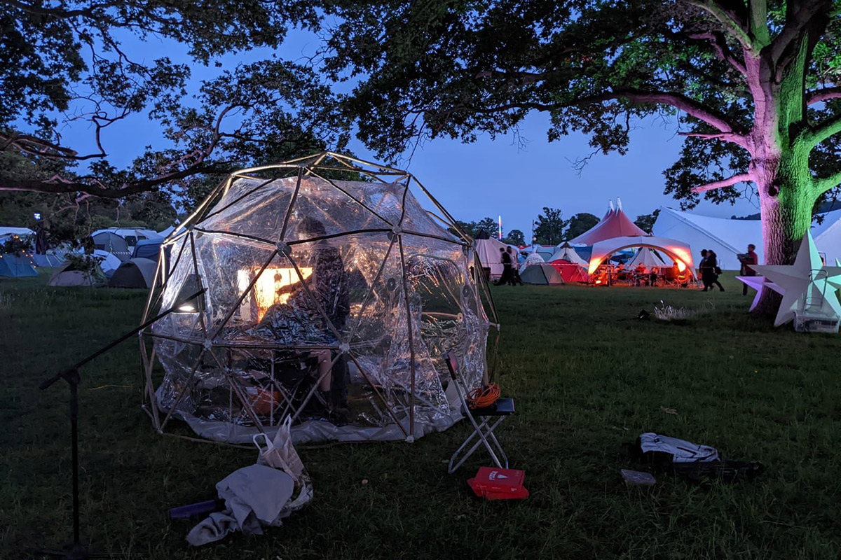
I think we had eight people in that dome at one point.
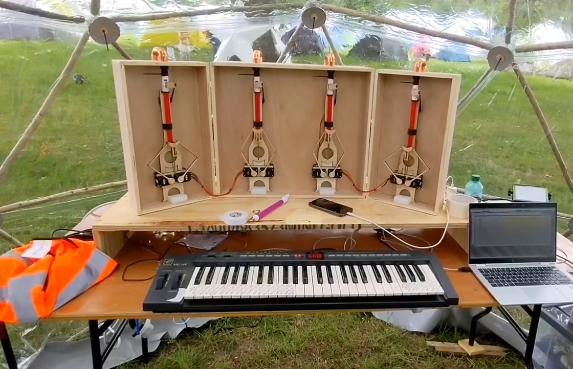
The orchestrion ran continuously for three days. I spent most of that time worrying about why it wasn't quite in tune and whether it was going to break at any moment. We set up a "jukebox" laptop with a bunch of MIDI files on it and a curses-based text-user-interface. The MIDI keyboard also allowed people to play it in real time.
It's a bit unnerving leaving a not-quite-finished project in the hands of the public and heading off to go enjoy the rest of the event. At one point I came back to one of the valve arms having snapped (which was easily glued back together) and another time I think someone accidentally yanked the power cable out of the laptop, which later ran out of battery mid-song and left the whistles hanging on one note. I probably should have made the MIDI-panic button more visible.
While I wasn't that happy with it, overall feedback from the public was extremely positive.
Completed pictures
It would be nice to finish the outside of the case, give the plywood some protective coating.
The doors could do with a latch on the front to keep them shut during transport (I just wrapped the ratchet strap around it).
The conduit connecting to the plumbing on the doors is removed for transport, but it would be nicer if there was somewhere on the orchestrion to store them. Just a simple bracket that you could hang them on would do. They aren't flexible enough to allow the doors to close without disconnecting them.
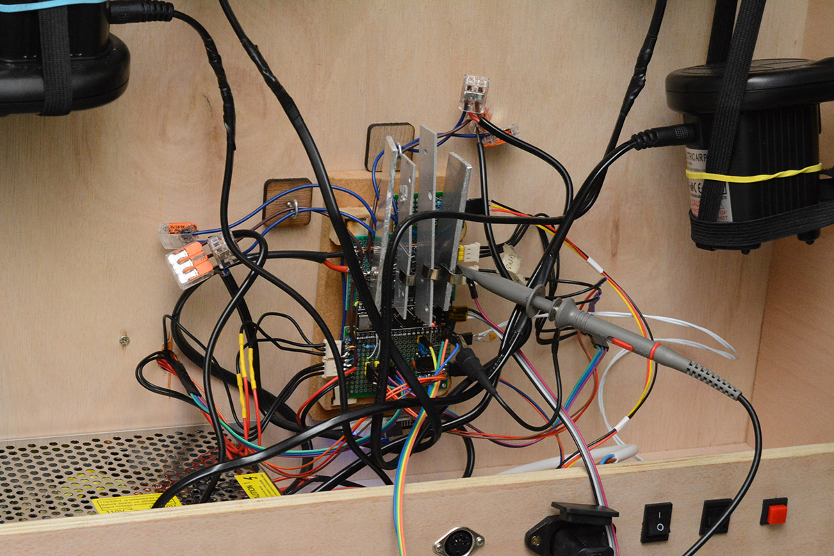
The circuit in its final form:
Conclusion and the Emulator
I think the appeal of robot slide whistles is mostly that we take an instrument that normally sounds terrible and with the power of computers we make it sound good. Part of the reason I fussed so much about getting it in tune was that if we fail to make it sound good, we've kind of failed at that main appeal. Not everyone agreed with this sentiment though.The Robot Slide Whistle Orchestrion will most likely make an appearance at EMF 2024. It's unclear if I'll have time to make any improvements to it before then.
As mentioned, there's the paper tape, the fixes to the tuning, the finishing touches to the case, one further thing I'd be inclined to try is tuning feedback with a single microphone. The fact is, if it sounds out of tune to our ears, it should be possible to correct the tuning with a single pickup. This will take substantially more processing than my original calibration script, to isolate out the four whistles and identify which ones need adjustment, but from a technical standpoint it's not impossible.
Arranging music for the slide whistles is quite labour-intensive. The page for the original robot slide whistle goes into some detail about this, with the limited articulation, enforced portamento, and 1½ octave range. In addition to the CAL script for fixing the staccato, I created a slide whistle emulator using WebMIDI and javascript. You can experience that emulator here. It was originally written to prepare music for the multi-tracked performances I did when filming the first whistle.
Something that hadn't escaped my attention is that by multitracking the first whistle, we could do four-voice polyphony. By extension, multitracking the orchestrion would bring 16-voice polyphony to the table. It would also be possible to downshift one (or more) tracks to extend the range. I had for some time planned to do an abridged arrangement of the 4th movement of Beethoven's 9th (i.e. the excerpt from Clockwork Orange, leading up to Ode to Joy) but squeezing it all into the limited pitch range was daunting. It may still happen eventually.
The source code for the Robot Slide Whistle Orchestrion is on github and git.mitxela.com. Similarly, the source code to the original is here and here.