
An even smaller, even sillier synth
13 Apr 2016Progress: Complete
I've been making a few USB devices, and logically the next step for me is MIDI over USB.
Luckily this really isn't any harder than the human interface devices. Instead of the HID report descriptors, we send these custom descriptors that follow the "Audio Control Interface" class, which has a MIDIStreaming subclass. Objective Development have an example of this, which itself is based on an example from a PDF file from usb.org.
It's all pretty straight forward, one thing to remember is that USB MIDI reports are four bytes, whereas MIDI messages are only two or three bytes. This extra byte contains a 4-bit cable number, for piping multiple midi streams through the same port, and a "code index number" which as far as I can tell is always identical to the status code of the midi message. See section 4 of the document for more about this.
I was going to make a tutorial on USB-MIDI, but got distracted when things went in a different direction. The start of the video talks about the right way and the wrong way to make knob inputs, based on my experience building the MIDI Interceptor. I plan to make a video about that soon.
Having got MIDI going from the slave to the host, I then tried out MIDI going from the host to the slave. When it arrives, the V-USB function usbFunctionWriteOut() is called, but only if you've enabled that functionality in usbconfig.h. Just for testing purposes, you understand, I made it create a square wave upon successfully receiving MIDI data. And it was annoying to have the square wave out of tune, so I dropped in a simple lookup table. Before I knew it, I'd accidentally made another chiptune machine.
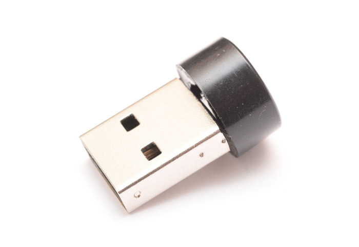
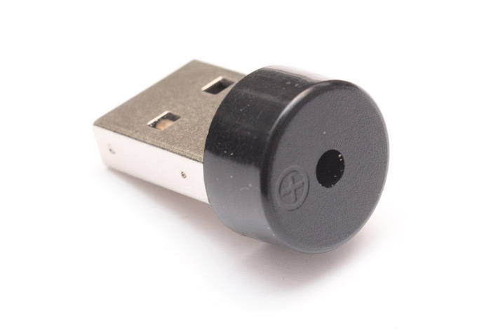
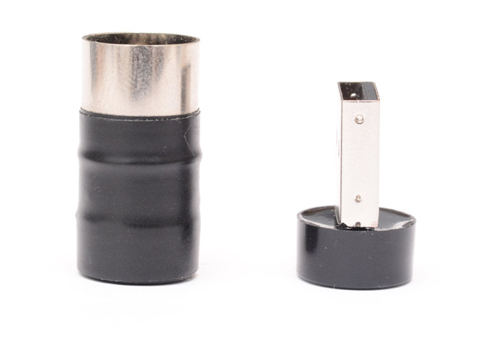
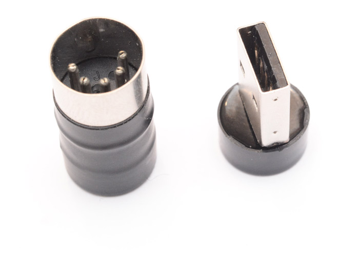
Whether this qualifies as a synth is irrelevant. Whether this is any use at all is irrelevant also. What matters is that a USB connector is less than half the volume of a MIDI-DIN connector!
A chance to break my own record methinks.
Construction
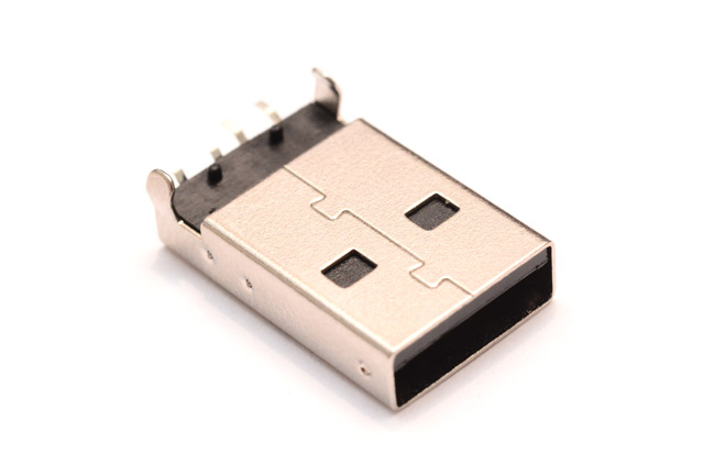
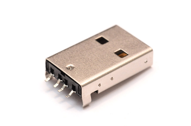
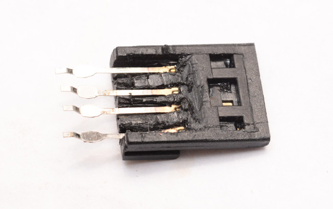
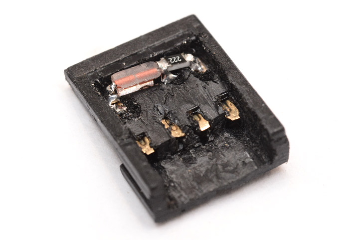
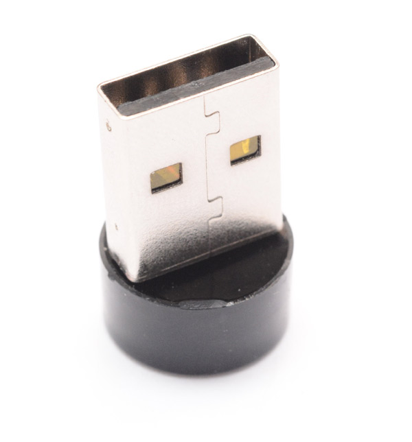
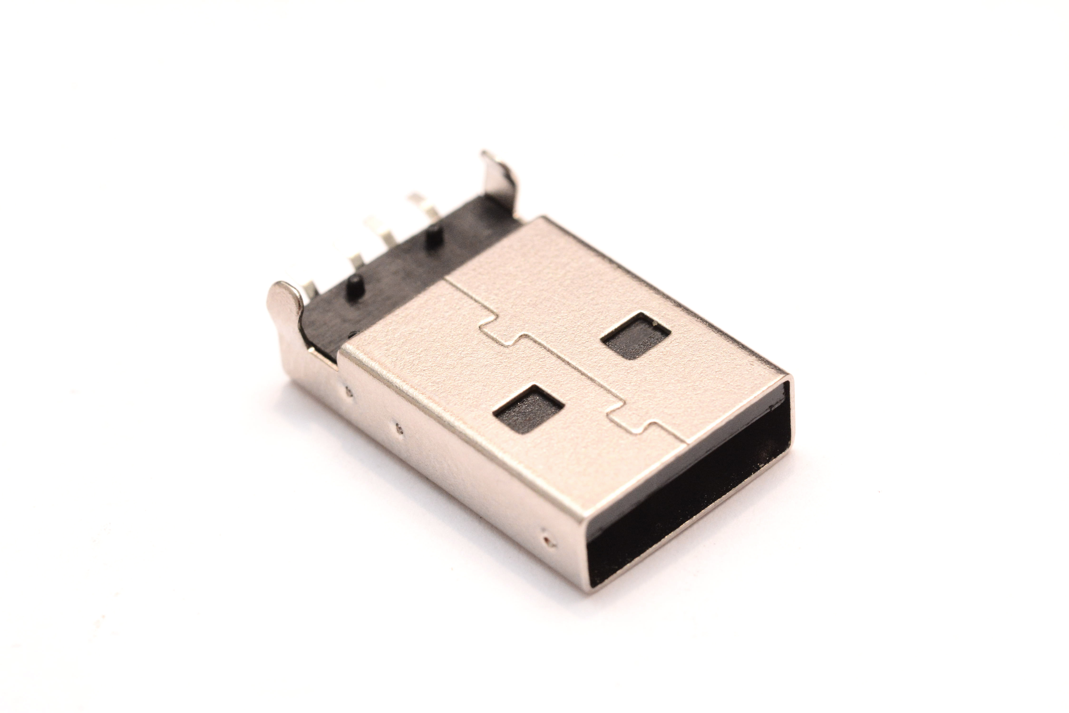
This is the USB connector we'll be using. And already, it's too long for us. We'll need to saw it shorter. But first let's separate the inner plastic part from the metal.
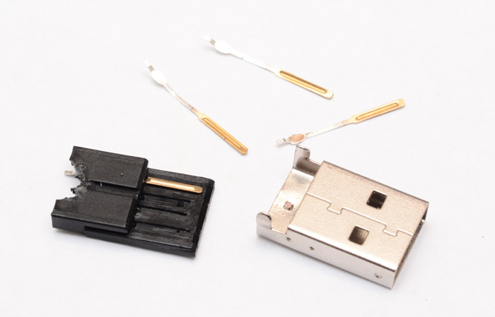
There's an indent on the top which stops the plastic sliding out.
I pulled the pins out of the way and then, after cutting away enough plastic to get at it, squeezed the indent flat, and the plastic can now slide out.
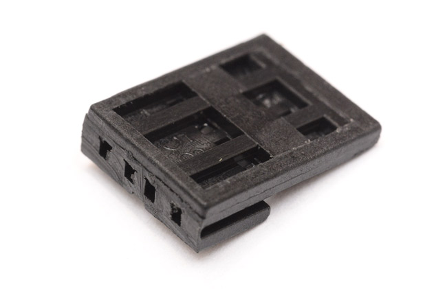
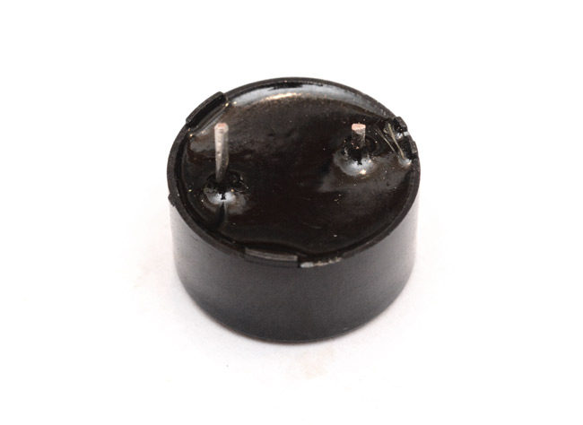
I trimmed the plastic to the length I was expecting (basically the minimum length for an ordinary USB connector). I wasn't entirely sure what the plan was at this point. Perhaps the parts should all be stuck flat against the piezo.
Maybe if we could just get the passives inside the connector...?
If we trim the pins back, there's more plastic we can clear out.
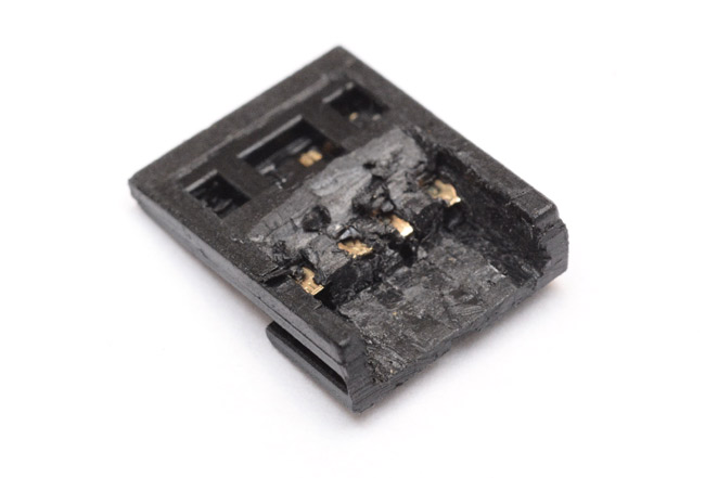
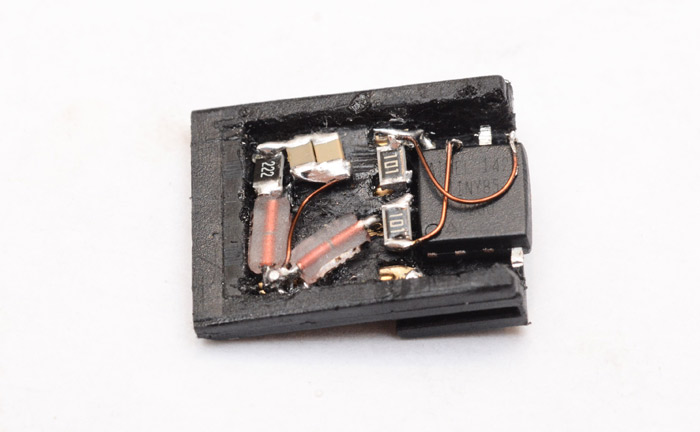
Hmm. The resistors, I've got surface-mount ones which can fit into the thinnest part of the connector with ease. But the zener diodes, there's no way they'll fit. Unless we give them a serious shave.
I took an old diamond grinding wheel, laid it flat on the desk and stroked the sides of a diode against it.
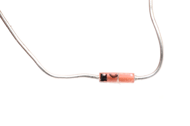
This was only half the way there. It looks like this is as far as we can go, but actually that's the lensing effect of the curvature of the glass. Looking at it from above, the junction itself is no larger than the wire diameter.
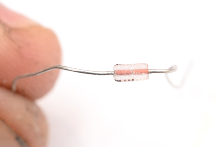
Some more grinding, and whadyaknow, it actually fits! We might just be able to pull this off.
The pullup for the data line is easy. Then we repeat for the other zener, and add some capacitance. I just bought a strip of 100nF caps in 0805 format, they're tiny! Excellent, we can comfortably give this device 200nF of filterage.
But is there room to stick the ATtiny85 in there as well?
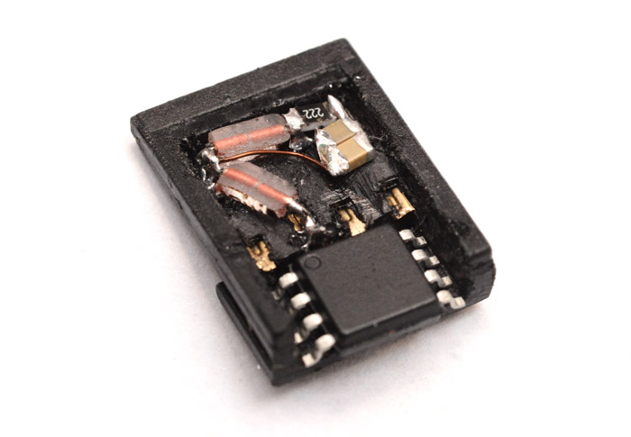
It sticks out a bit. We may have to grind down the ends of it as well. And chop off the unnecessary legs. Remember to program the chip and set the fuses first!
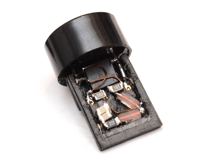
Sticking the data terminating resistors sideways like that was a stroke of genius. Although it makes it very difficult to solder to the outer two pins without shorting everything. I bent the data legs of the chip upwards, to make it easier to wire to them and also to keep them out of the way of the piezo's legs. They need to protrude into the device enough to give it mechanical stability, since that's what we're going to be pulling on to unplug it. The underneath of the piezo is actually concave, so there was no need to excessively grind down the chip.
The piezo is soldered to the sound output of the chip, and to the ground. It is also making the connection between the chip ground and the ground pin of the USB. Soldered in three places means it's difficult to remove.
To be fair, I probably should have tested the chip was working before soldering it in like that.
I carefully put a piece of paper over the circuit, and slid the device into a USB extension cable. Does it work? does it work?
"USB Device has malfunctioned" Oh, my favourite windows message...
At this point the self-doubt sets in. Did I remember to set the fuses? It's so difficult to scope this circuit, especially when it's connected, but from what I could make out the chip was turning on and doing some signalling. If the fuses were wrong, this would explain why the host thought it was gibberish. Since I hadn't tested the chip before, there was only one thing to do...
Desolder the piezo, pull out the chip, and rig up some kind of testing arrangement.
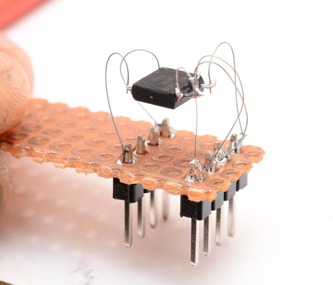
This involved soldering to the reset pin, which I had snapped off / filed away. Luckily there was just enough bare metal available to make a connection.

Sweet sweet chiptunes. Nothing wrong with the chip then. Of course I remembered to set the fuses – I'm not an idiot! Pah. Pahpahpah.
So I suppose something wrong with the passives then? I'd made sure to test the zeners after each grinding, just send a few mA through and measure the voltage. I'd continuity-tested everything as it went together. Hmm, wouldn't hurt to test it all again...
Eventually I found the problem, and it was one of continuity. The D- line resistor, and the zener, were well soldered to each other but some of the plastic had melted between them and the gold connector. Nothing that can't be fixed with a soldering iron, tweezers and some leet skillz.
Skipping some of the boring pictures, finally, we had our silly synth plugged in and working.
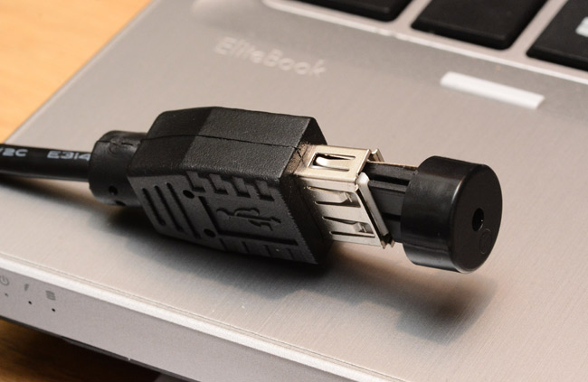
This extension cable was the easiest to test with, as it lets you grab by the plastic instead of the piezo. All my other extensions protrude right up to the piezo, which was not yet properly attached.
The last thing to do is fit the iconic metal housing. First I cut it to length with a hacksaw. The plastic is jammed inside, but one thing I had to worry about is the metal shorting my circuit. The simple addition of a layer of kapton ought to do it. Wrap through, then trim off the excess with a knife.
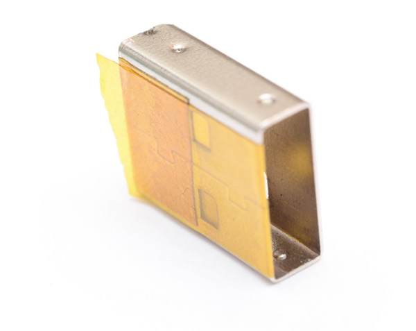
The thickness of the tape actually has a significant effect. It took some additional filing of the zeners and bits of solder before I could slide it together. At last, we had our silly, pointless, but extremely tiny chiptune machine!
Whole thing took about... four or five hours. Gosh. Time flies when you're having fun eh.
You can just make out the circuit, peeping through windows of kapton tape.
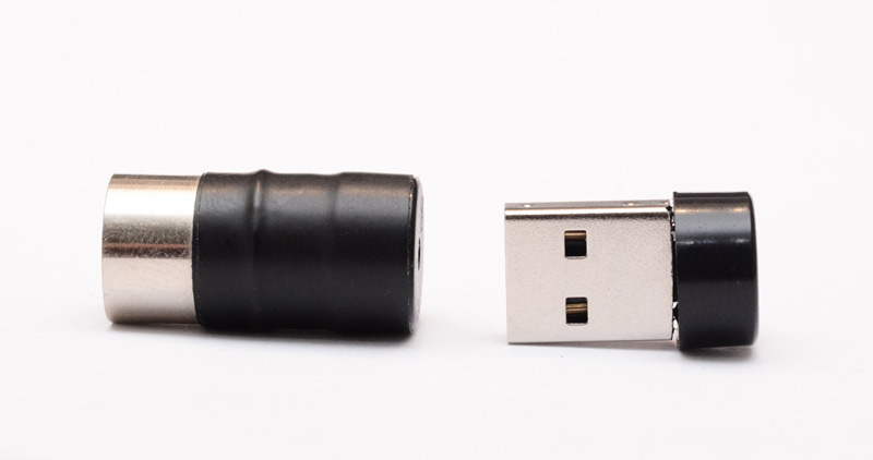
Now for some comparison shots with the MIDI-DIN version
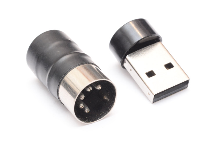
The most hilarious part is that while the MIDI-DIN one does have some utility – for instance, testing if MIDI data is coming through on a cable, or adding functionality to a battery-powered keyboard that has no onboard synth, such as the Yamaha KX5 – the USB version has none. It can only function if you have a USB-host to plug it into, which would already be able to run a synth!
Completely pointless. But so... satisfyingly pointless.
There may yet be an even smaller "synth" to come. Micro-USB?
Update: As requested, here are full resolution versions of some of the pictures:
1,
2,
3,
4,
5