
Sewing Machine
23 Nov 2013Progress: Abandoned
Sewing machines are grand pieces of engineering. Despite their seamstress connotations there is something very manly about the mechanism, particularly for the older and manual machines, using the force of oiled brass and cast iron to perform the delicate duty of needles and thread. The core idea has not been lost even on the newest and most plastic productions, which still utilize the mechanical marvel that is the lock-stitch mechanism.
It's a queer type of mechanism, though. It falls into the unusual class of constructions which look simple but are deceptively tricky to get your head around. I had seen animations like this:
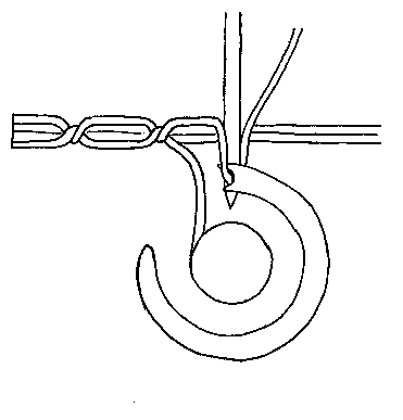
...which at a glance seem to have everything under control. But to understand how something works truly, you have to be able to build it. And that animation simply doesn't carry enough information.
Under the spell of this conundrum I found that I simply must build a sewing machine.
The following is a brief account of my attempt throughout May/June of 2011. It's yet another case of me not being able to find the dev photos - sorry. I've been putting off posting this for so long that there's no point delaying any further.
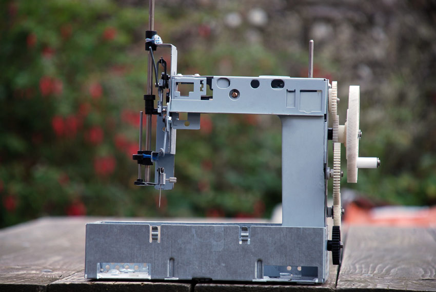
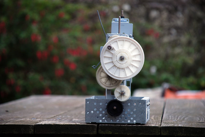
The singular source of parts, bar a piece of coat-hanger wire, was broken printers. They are abundant and rich in interesting mechanisms. They are also a good source of iron (ahem, soft steel). I also bought a needle, and a standard sized bobbin.
Obviously the machine isn't finished. It got to the point where I could make a few stitches, on condition it was cranked very slowly and the material was hand fed. I did not get round to building a feed mechanism, that was next on the agenda when I abandoned ship.
The main problem I encountered - and should have anticipated - was the lack of rigidity. It really is essential to have the needle and bobbin case line up as well as possible. This probably explains the copious quantities of cast iron you find on a Singer. Had I continued the build, I would have added lots of support braces.
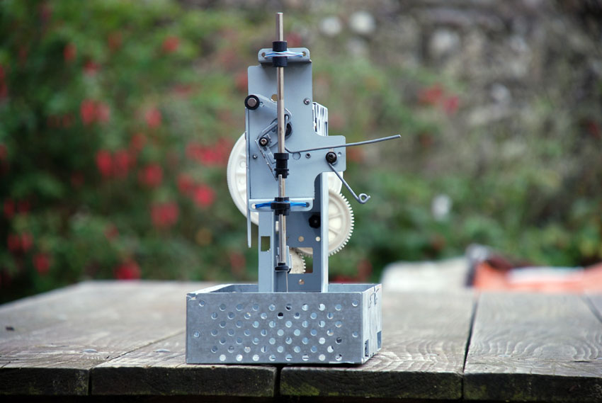
The arrangement of cams and sticking-out wire is the partially constructed, but working, tensioning mechanism. The phase of the tension tug is set to 90 degrees lag on the needle. This allows plenty of slack for the bobbin to jump through but ensures that the final stitch is tight. It's one of the four key steps in lock-stick sewing: needle down, bobbin through the loop, pull up the tension, and feed the work along for the next stitch.
It's worth noting that I had no reference for this when I built it, apart from the excellent video known as The Secret Life of Machines: The Sewing Machine. Watch it. Go and watch it now - it's worth your time. But I didn't have a physical object to inspect. The video only shows the key point of the bobbin/shuttle lock stitch mechanism from one angle. (It's also a peculiar model halfway between the original shuttle mechanisms and the modern bobbin style; I couldn't get that mechanism to work with the standard bobbin I had.)
At the time, I didn't own or have access to a lathe. But there were a few moments when I had to clamp a drill in a vice and pretend.
The counterweight is visible; the long bundle of metal rods wrapped in tape. They're supported by metal pegs through the shaft. I built a special vice that would let me drill through the (orthogonal) centre of the rods. It's ridiculously hard to do freehand.
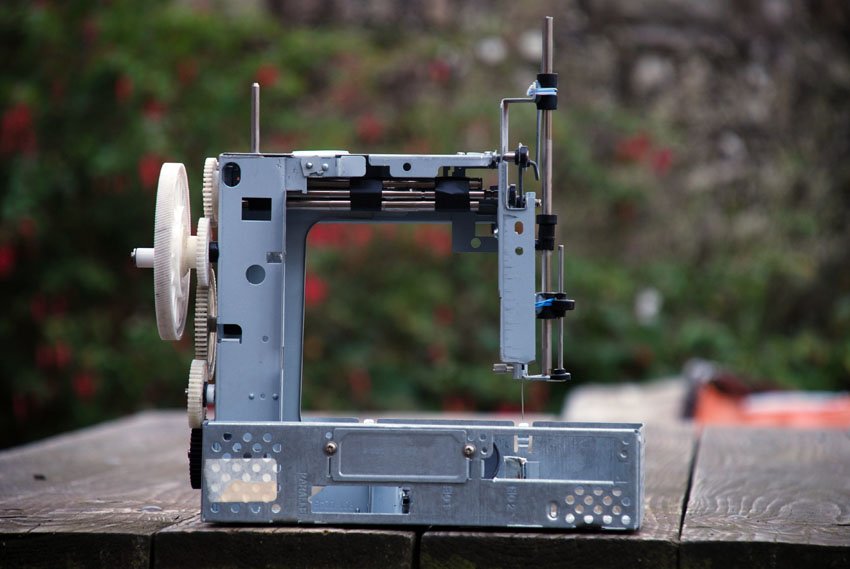
The bizarre arrangement of gears is all I could come up with. In a box of over one hundred plastic gears, all from very similar printers, I only found two pairs (and they were different to each other). It's important, of course, that the upper and lower shafts stay in phase.
The black gear/shaft is spring loaded. Not only does this facilitate the removal of the bobbin holder, but it disengages the teeth so the phase difference can be adjusted.
So. The heart of the machine, and absent from the pictures above, is the bobbin holder. On earlier machines it was called a shuttle, since it really did work like the shuttle of a loom. Shown below is my third iteration, and the only one to actually sew.

Through a combination of scraps and solder, this shape meets a few requirements. The beak catches the loop of thread that protrudes as the needle starts to retract. It then pulls it over the entire structure as it turns, guided by the wire mesh.
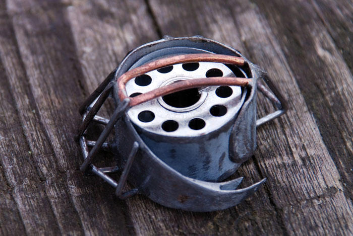
The key point, which isn't illustrated in the animation at the top, is how to turn an object which needs to be free on all sides so that thread can pass over. This was the first of my designs that actually worked: the copper/brass wires on the back are turned by a loosely fitting paddle. When the thread starts to tension, the paddle is in the vertical position and friction is minimized.
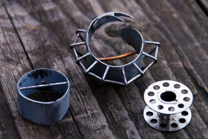
As mentioned, it would only work at very slow speeds. So for the next iteration I think I would move to a smaller, much thinner bobbin, like the earlier machines had. They held less thread, of course, but were easier on the tolerances of the mechanism.
The last work I did on this was the summer of 2011. I only stopped because I felt I was over-schedule (in the back of my mind I was aware that Singer took only 11 days to build his first prototype) and the primary goal, to prove that I understand how a sewing machine works, had been achieved. Possibly.
I do recommend watching all of the Tim Hunkin/Rex Garrod videos if you can; they're excellent.
Shortly after coming to a halt, someone donated a sewing machine to me (out of pity?).
Well, thanks for reading. Until next time... (that is, next time I feel the effort to write up another long-abandoned project)...