
Simple Screw Counter
28 Feb 2026I have wasted a significant chunk of my life counting out small numbers of parts into bags and posting them to people.
It's not that I'm complaining about the popularity of my precision clock kits, but it does feel like the time could be better spent. I'm apparently such an anxious person that until recently I wasn't even comfortable listening to the radio or a podcast while I work. The risk of making a mistake, posting the wrong number of parts to someone, was too great.
But the process is kind of zen, so during the long hours of manually counting out nuts and bolts I started to dream about automation.
Here's a video demo of today's creations:
Nut Dispenser
By far the quickest win here. Nuts are tedious to pick up with your fingers, and during the endless toil I dreamed up a gun that could shoot out six nuts at a time.
The laser-cut acrylic sheets are pegged together with scrap PLA filament. I laser-cut the holes at 1.6mm diameter, with the kerf of the laser that ends up being about 1.7mm, and the standard filament is 1.75mm diameter. The conical kerf means it starts easily and then jams to a press fit. I last demonstrated this technique on the Portable Probability Panel.
The pivot for the trigger is a random bit of metal I had to hand. Possibly, we could have used filament here too, it probably would have been fine.
I should have made the hopper bigger, but even this is enough to hold over a hundred nuts. I might add a few more layers, or maybe cut it all out again bigger – but it's already good enough that it doesn't really matter.
Screw dispenser attempt 1
Emboldened by my effective, err, nut shooter, I turned my sights to the screws.One of the confusing things is that I did a fair bit of searching for prior art and everything else that I could find was far more complicated. That does imply that the simple approach is not going to work. Even the rotating disk style of screw counter has issues. The arduino is not just for counting the output, but to detect when it jams and reverse the motion to shake it free.
Surely just sticking a slot along the base of the nut dispenser isn't going to work?
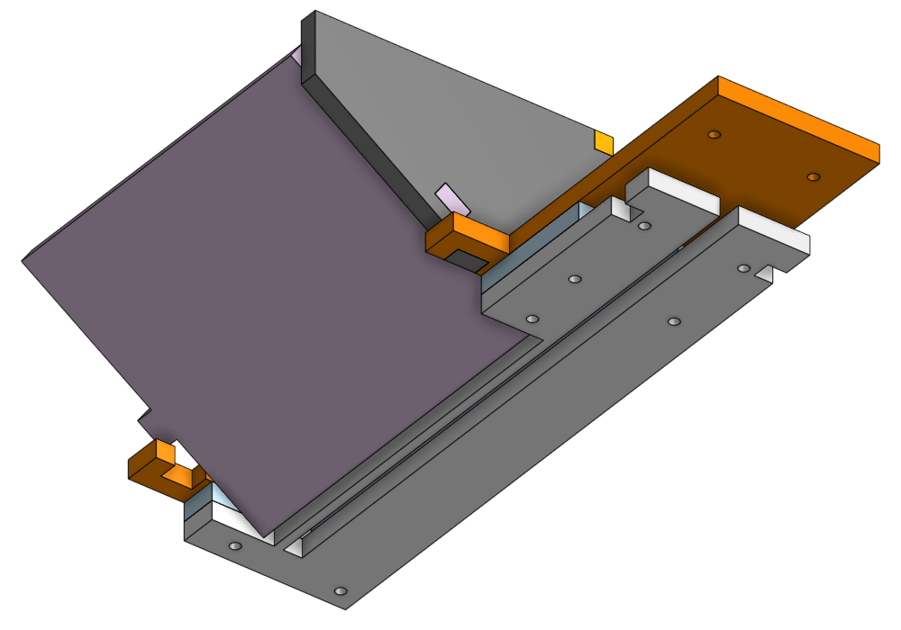
I accidentally used matt acrylic for the top layer here but you can still see what's going on. The hopper was glued on using the offcuts of making the nut dispenser.
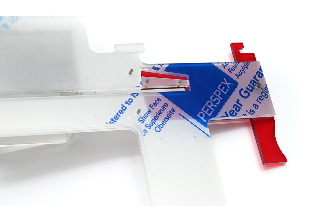
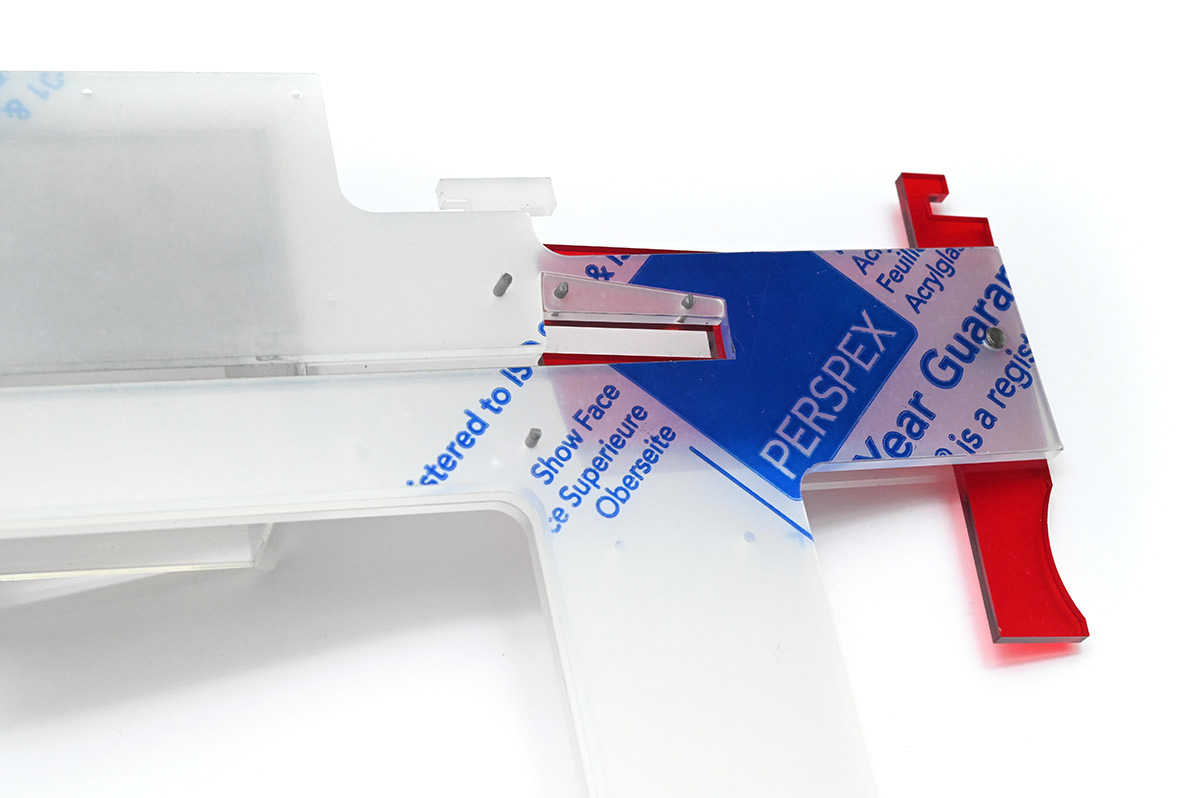
The slot is 3mm, in a 6mm channel for the heads of the bolts to ride along. Originally the hopper was just a cuboid, which worked OK but there was a chance the screws could land incorrectly and block the channel, like this:
To solve this I added the ramp section, so if a screw ends up head-first it's encouraged to rotate around and drop into the slot. To retrofit the ramp, I had to file the end of a piece of acrylic to have a chamfer so it sits flush. With this, even gentle wiggling is enough to get all the bolts to drop through.
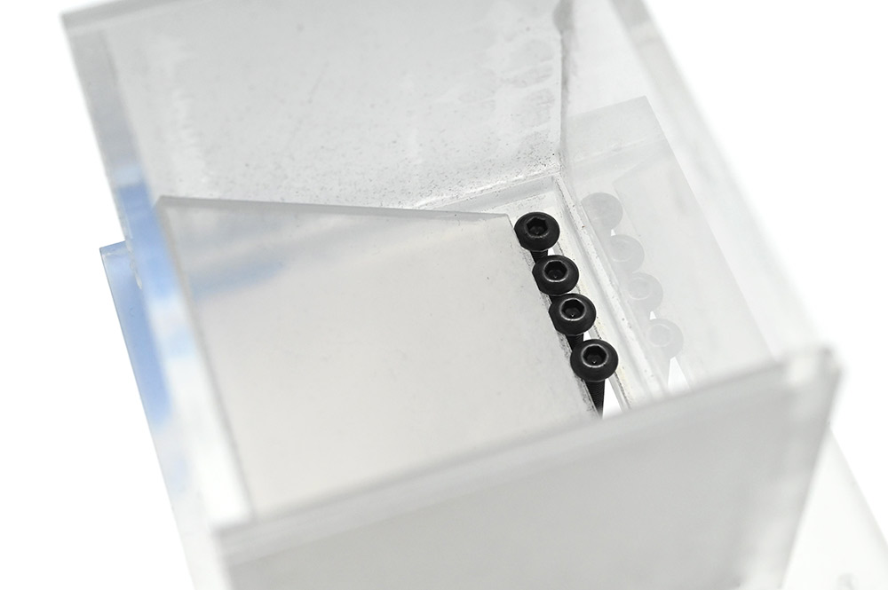
The dispensing mechanism itself is only marginally more complex than with the nuts. There is a lip pegged into place. In the closed position, the slot between the lip and the other edge is about 3.5mm wide.
The bolt heads are around 5.5mm wide, and maybe 2mm tall. The middle layer of acrylic is still 3mm thick because I hate mixing different thicknesses in a project.
It's important that when the trigger is pulled, the path is blocked for the remaining screws so that no more fall through.
I wasn't sure of the exact length for six bolts, but after taking a guess and checking I re-cut the trigger part to adjust it and after that it was perfect.
So. This screw dispenser worked really well, but the hopper was far too small. And filling it to the brim doesn't work, it needs to have enough room for the screws to jiggle around when you shake it. I briefly tried fitting a lid to it and found the over-filled hopper to be too finicky.
Screw dispenser attempt 2
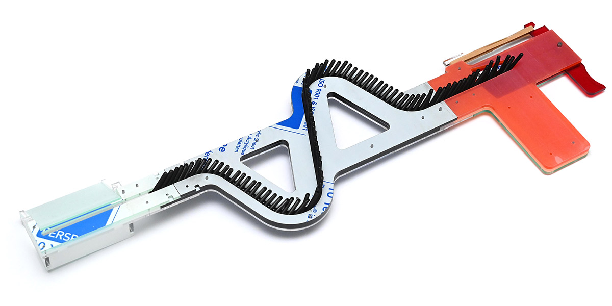
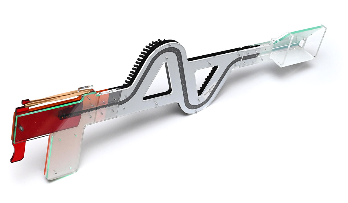
I didn't actually try it, but I had the feeling that making a huge hopper that could hold hundreds of screws would end up completely impractical. But once the screws were in the channel, the mechanism worked great, so instead I decided to keep the small hopper and build a really long channel.
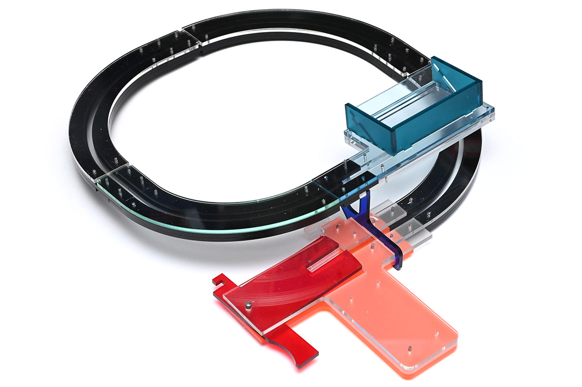
The tracks are joined by a somewhat standardised connector I made, consisting of the three layers staggered with holes 15mm apart. There are little cutouts where I assumed I might need other parts to connect later. Before starting this I was envisining multiple laps, a helter skelter of sorts, but even one lap should be enough to hold over 150 screws.
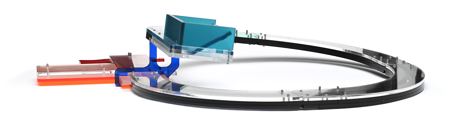
The first three sections have a turn radius of 100mm, the last has 80mm so that the track doesn't obscure visibility of the dispensing mechanism. It's vital to be able to visually confirm that six are loaded before we pull the trigger.
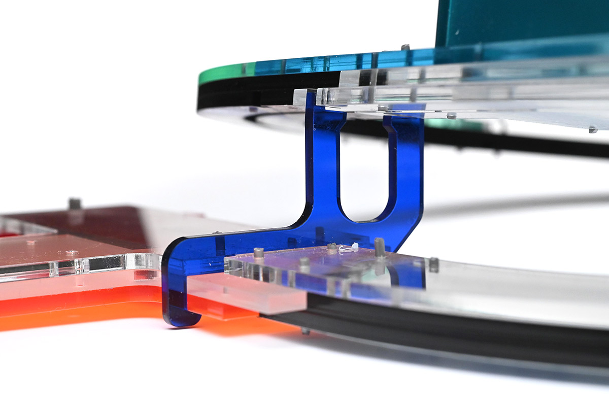
The blue section that supports it vertically is hooked over and clipped into place. No glue needed. It holds the hopper at a slight angle, and the U-shaped section allows screws to slide through.
The main problem with the design, apart from being a bit of a handful, is that about half the track doesn't see use. Once it's full to the apex, trying to load more screws mean they start to fall back along the track. It works if you put your finger on the track to stop them returning, so maybe some kind of one-way valve might have helped. But really, it would be easiest if the track is always going downhill.
I suppose we also could have reconfigured the tracks to produce a huge S-shape, but if we're going to do that, we might as well make a new S-shaped track that'll be a lot less floppy.
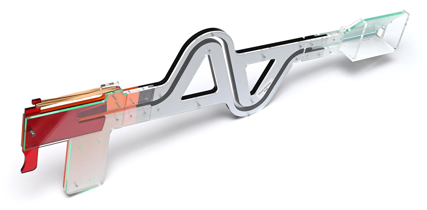
Screw dispenser attempt 3
It's unclear how tightly we can turn the track. I ordered more acrylic but while waiting for it to arrive I didn't want to plough through all of the bits I had left. But at least we can parametrically model the curve, and adjust things later. All the dimensions, apart from cosmetic ones, are derived from the three numbers: 21mm, 40mm and 135°.
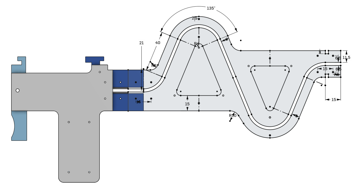
Turn radius of 21mm seemed sharp, but after cutting it out it seems fine. The aim was to fit enough screws for 15 sets (in actuality, it holds 16 and spare) and also keep the acrylic parts shorter than 210mm (the width of an A4 sheet).
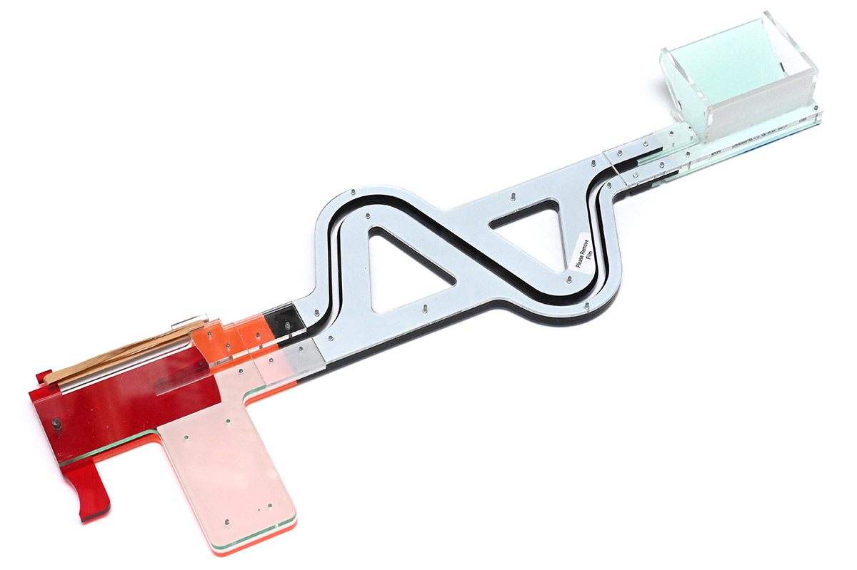
It's easy enough to hold. By pure coincidence, the middle triangle is almost perfectly at the centre of mass. I could hang it on the wall when not in use.
I kept the hopper tiny, for weight reasons. I also redesigned it slightly, removing excess weight and adjusting so it doesn't need any filing for the ramp to meet the track.
The very thin part means assembly needs a bit more care, but once it's together it's fine.
It possibly could have benefitted from a bigger hopper/funnel. In use, I spend a few seconds seconds dribbling screws into the hopper a pinch at a time, until the track is full, then dispense a bunch of sets into paper cups. It is substantially faster than counting out the screws individually and carries a lot less risk of making a mistake.
Potentially we could have added an exit funnel, so they're dropped into a shoot that can be aimed more accurately. In this case, using a bunch of paper cups it's quite easy to pick up the cup and hold it under as I pull the trigger, but maybe an extra funnel would let us aim the output accurately at a bunch of cups in a row.
Another idea I mentally toyed with was to have a separate hopper and magazine. We could have a big funnel to chuck all the screws into, which then disconnects and we just dispense from the track without the weight of a huge hopper on the end. It's unclear if the incremental improvement is worth it.
Magnet dispenser
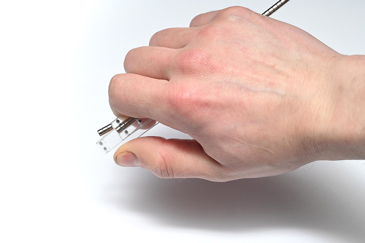
Wasn't worth demonstrating in the video, but I also made a very simple magnet dispenser. Each kit needs three of these 4mm diameter, 3mm thickness magnets. This simple laser-cut shape holds a strip of them, and pressing in the lever shears off three of them.
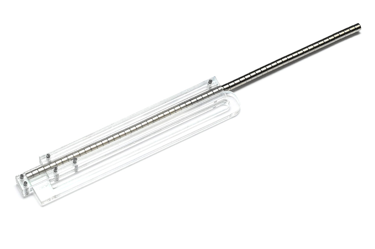
The design needed some fettling to work correctly, it's hard to predict how the acrylic flexure will behave. It also probably could benefit from ejecting the magnets further. As it is, they're sufficiently attracted that they don't drop off on their own. But, it's perfectly serviceable as an easy way to grab another three magnets effortlessly.
CAD files
I've chucked the step files and a bunch of DXFs here. I make no guarantee about any of it, you'll probably want to adjust things to suit if you plan to use these.The designs were done using a free trial of OnShape, after their marketing department reached out to me with an offer to sponsor my channel. Unfortunately I must have hurt their feelings as they stopped responding to my emails.
You can probably guess my opinions on it though, the software is very good but the cloud-based vendor lock-in is grating, and the free tier is hobbled beyond the point of usefulness. On the plus side, being browser-based, it works perfectly on Linux.
The 1.1 release of FreeCAD should be soon. I really want FreeCAD to succeed, but blimey they have a big hill to climb. My fingers are crossed.