LED Industrial Piercing
22 Dec 2023Progress: Complete
A friend of mine wears a type of jewellery known as an "industrial piercing" or "scaffold" that puts a bar across her ear.
Always looking for a new challenge, I had the idea to fill the bar with LEDs.
Watch the following video to experience the journey:
This is one of a number of projects I rushed through in the run-up to the closure of London Hackspace. I've now not had access to a milling machine for over a year. Drilling holes in the side of a hypodermic needle would be a little tricky without one.
Design
Our journey begins in the summer of '22, when I snapped this image of my friend's ear. (With permission!)
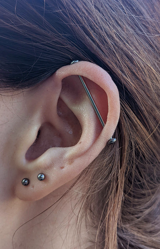
Could it be filled with LEDs? Most people laughed in disbelief when I suggested it. But everyone agreed that it would be really cool.
You can buy stainless tubing in various sizes, but nothing quite compares to the cheapness and availability of hypodermic needles. A gauge 16 needle is exactly the right diameter, and the sidewall is so thin you couldn't ask for anything better. But needles are quite short, there was some concern that it wouldn't be long enough. I did find a supplier of extra long syringe needles intended for model makers, there might have been something in the right size, but after some careful measurements and calculations I decided the regular needles would be OK.
I did the initial design in OpenSCAD, and having rotated the above photo into a scaled and skew-corrected position we could overlay the two in photoshop.
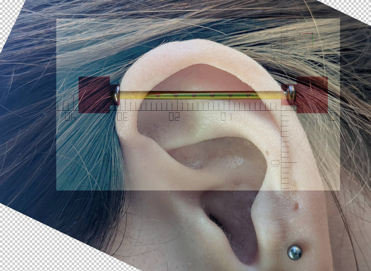
That's before the final adjustments to length were made. This mockup was invaluable in getting the LED pitch and offset correct.
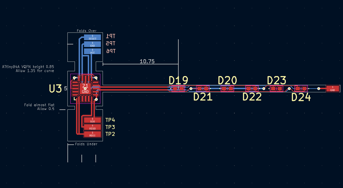
OpenSCAD continued to be helpful as I came up with the circuit, thinking about how it would fold together and how much tolerance we needed to leave. Just a basic idea is all that's required.
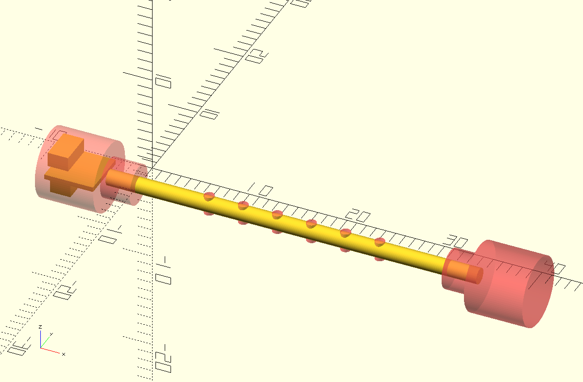
The PCB design had to wait until I'd gotten this all exactly right, the distances between the microcontroller and the LEDs is critical.
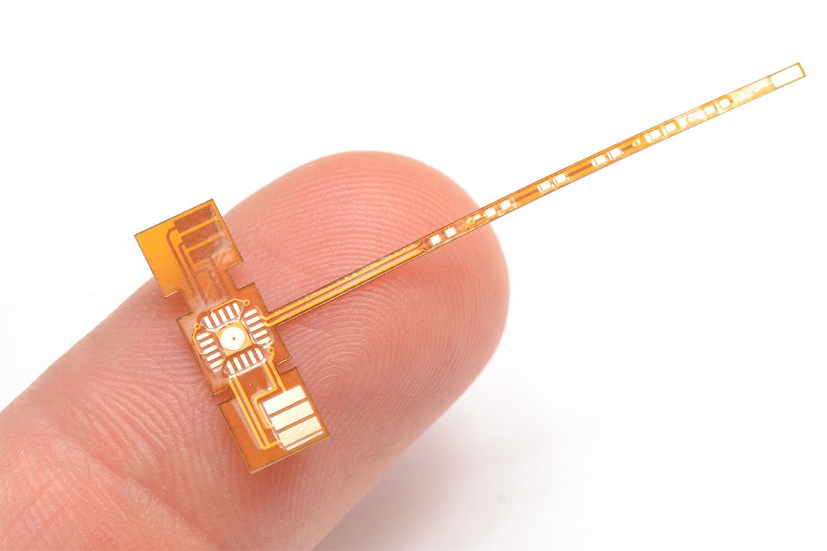
A flex PCB is the way to get the very thinnest board possible. You can technically get 0.2mm FR4 from some board houses but it'll cost about the same as a flex PCB anyway. We could have gone flex-rigid, that would have let us use the thinnest material for the LEDs and a multilayer board for the microcontroller, but it would have cost a lot more and still not allowed us to put a connector above the microcontroller.
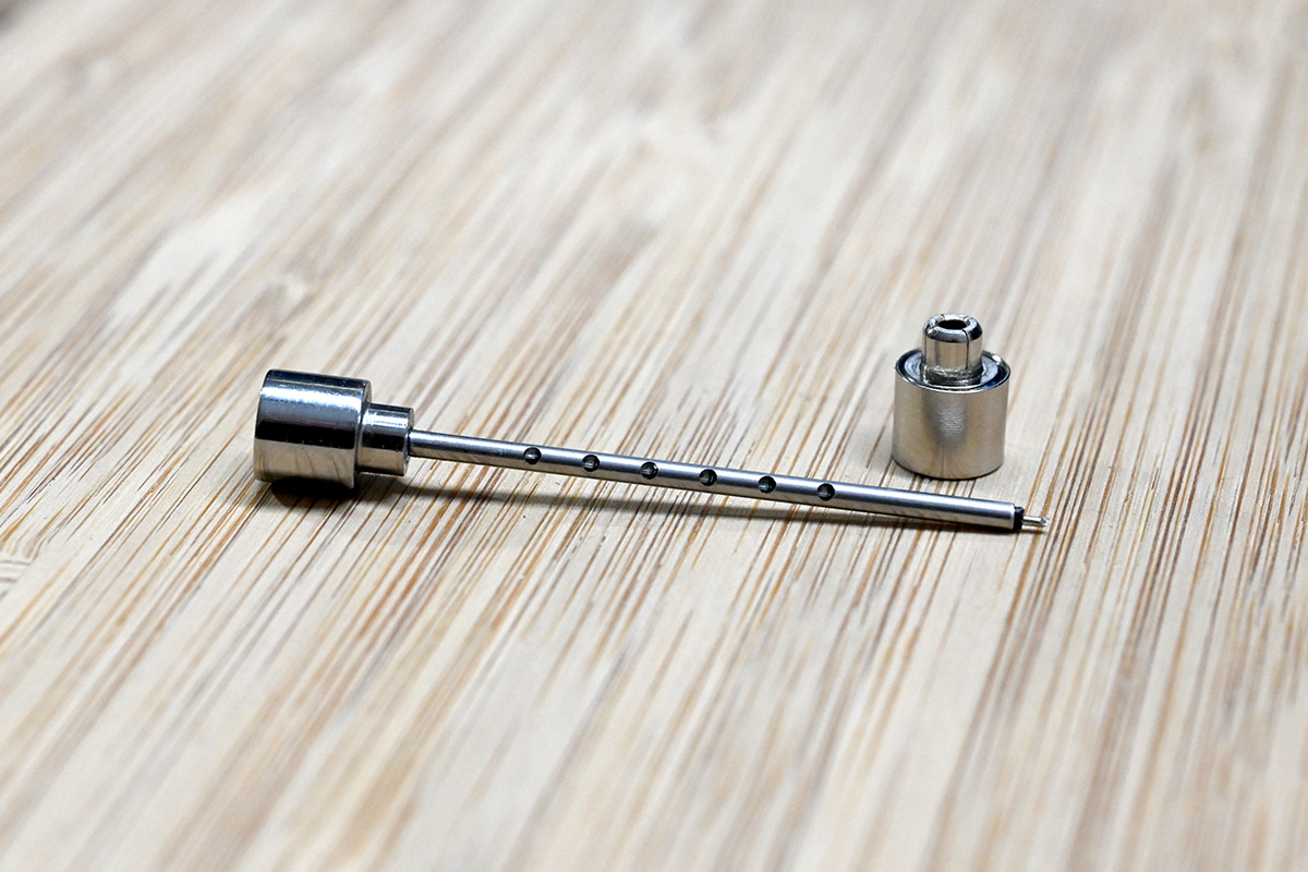
Once I'd settled on those off-the-shelf earrings as the source of my battery holder, that determined quite a bit about the design too. The metal case is our positive battery terminal, we need to fit a wire that pokes out of the end of the needle to be the ground pin.
I did a few redesigns of the board before settling on the above design. Even forgetting the fiddly exact dimensions of how it will go together, routing the LED tracks was tricky. If we had gone for the 0201 LEDs they could have been mounted in the other orientation, with tracks passing directly underneath them. Once I'd checked the dimensions I felt a lot more comfortable with the 0402 LEDs though.
Metalwork
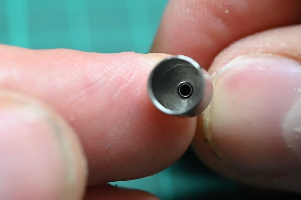
Once I'd made the tiny brass V-block arrangement, crossdrilling the needle took barely five minutes. In my mind it was going to be a big deal.
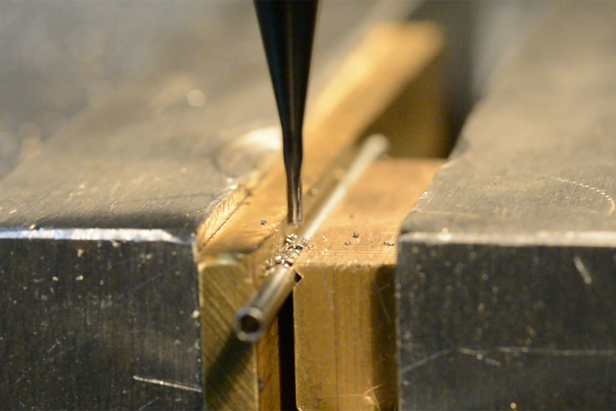
It helps that I used an endmill to drill the holes, not only would a drillbit have wandered on the curved surface but the carbide is simply a lot stiffer. I should really invest in some tiny carbide drills, you might say that HSS just doesn't cut it for me.
The dodgy-but-still-kind-of-legit tactic of holding an endmill in the tailstock chuck no doubt made some viewers grimace.
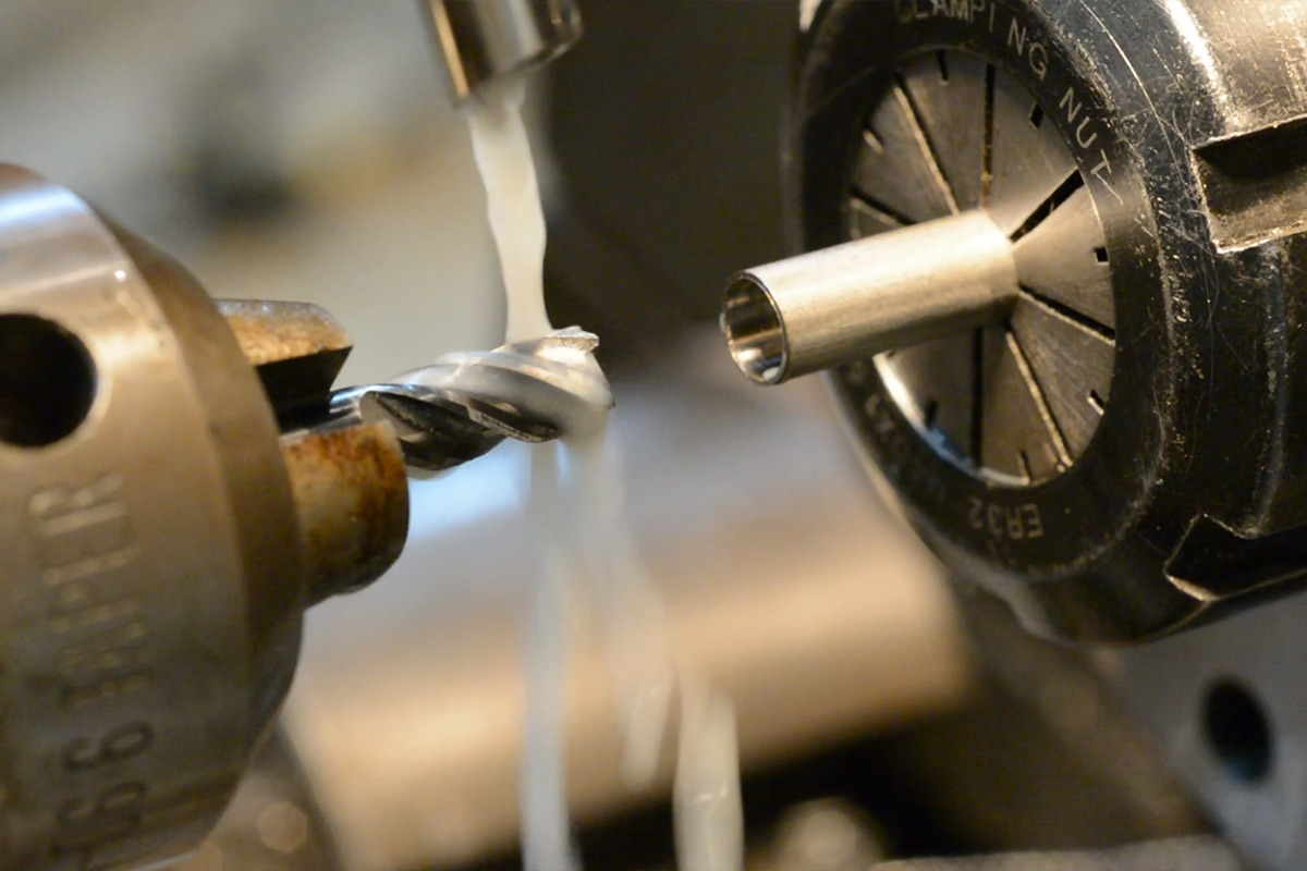
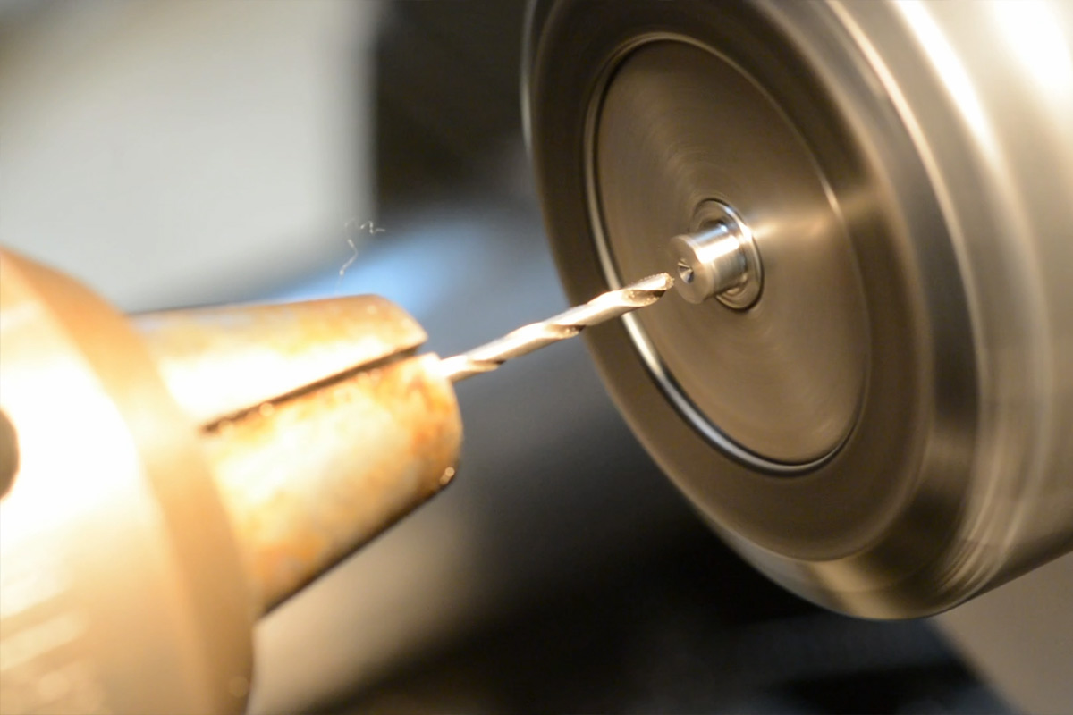
Drill shanks are soft, chuck jaws are hard. Endmill shanks are also hard which means the jaws won't grip them properly. If I'd had the proper tools I would have used them. Anyway you can't argue with the results, the flat-bottomed hole was spot-on. The 1.6mm through hole was a lot messier, the drillbit really wanted to wander. Again I yearned for all my tooling to be solid tungsten carbide.
This formed a decent press-fit onto the needle. I suppose the hollow tube is fairly compressible. Even so, once I'd settled on the right position I gave the needle a healthy smear of cyanoacrylate before pressing it in for the final time. Remember, the battery-holding collet on the other end is going to be mounted and unmounted by simply pulling on this join, so we want it to be very secure.
Circuit
When the circuit boards arrived, I soldered one together almost immediately.
For multiple reasons I then put it aside for about a year. It was only a few months ago that I powered the board up and got some flashing patterns going.
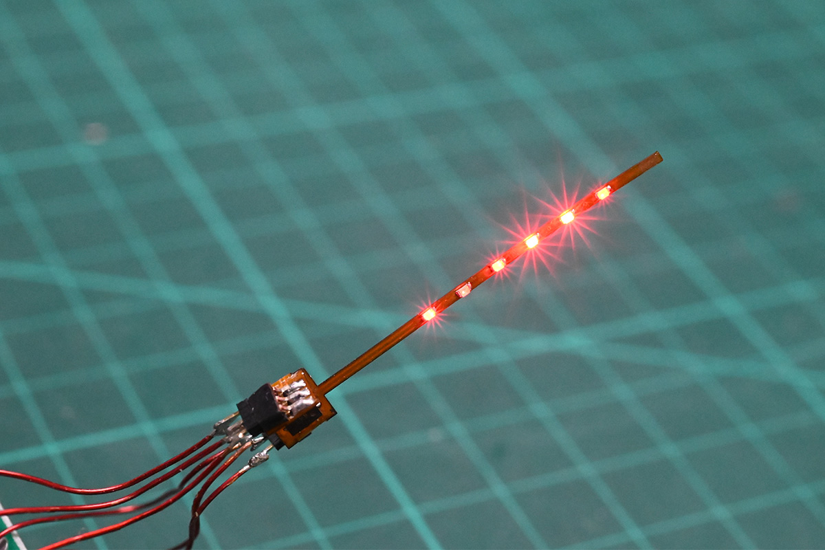
The microcontroller is an ATtiny44. If I was designing this today I'd have gone with the CH32V003, which admittedly has worse power consumption, but the benefit of that one-wire debug pin can't be overstated. It now seems so silly that I had to wire up six pins to be able to reflash this thing.
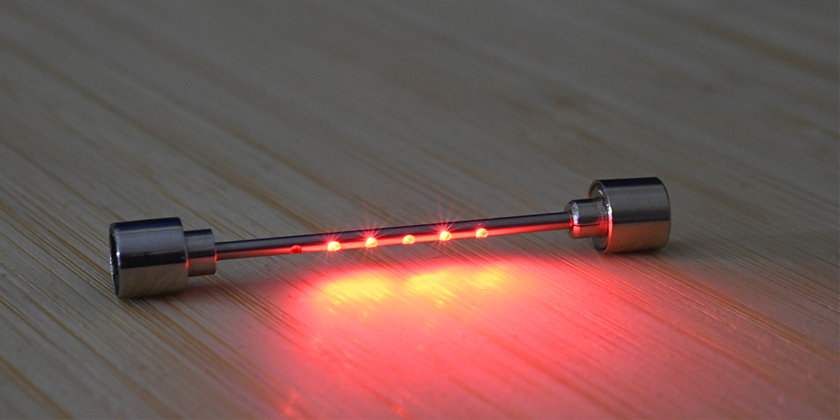
Sliding the circuit inside of the case and it already looks nearly finished.
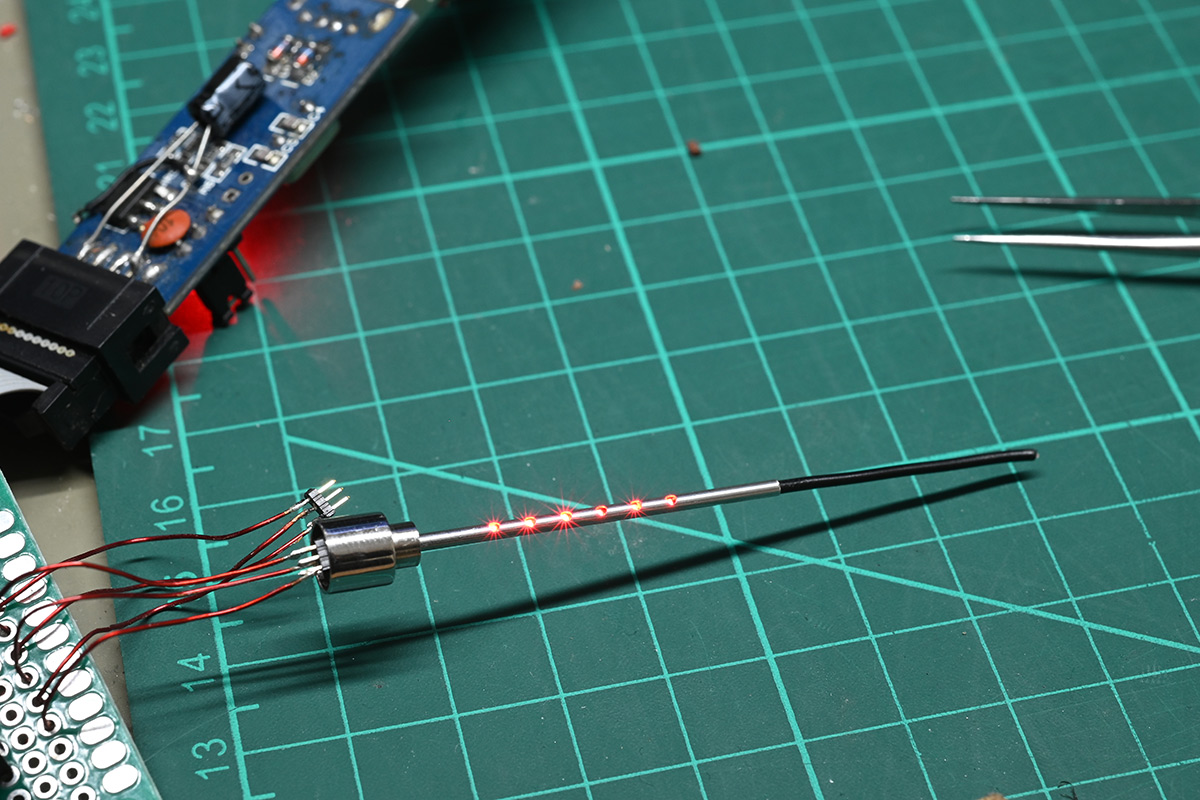
The thick black wire protruding from the end needs to be trimmed to form our battery negative terminal. But as you can see the power and ground pins are also exposed on the connector.
In terms of software, the LEDs are charlieplexed and the pattern I settled on loops over the course of about three minutes. All in, the software is similar but a fair bit simpler than the charliestar, which does more with less.
I will link to the source code at the end of the page.
Assembly
I should mention, the cheapo earrings I used for the battery case are not made from stainless. It's nickel-plated brass, which I realised when I started machining it. It does make me think I'd have had an easier time making the end out of brass and nickel-plating it. On the other hand the stainless does look pretty good, and with any luck it'll stay that shiny for a long long time.
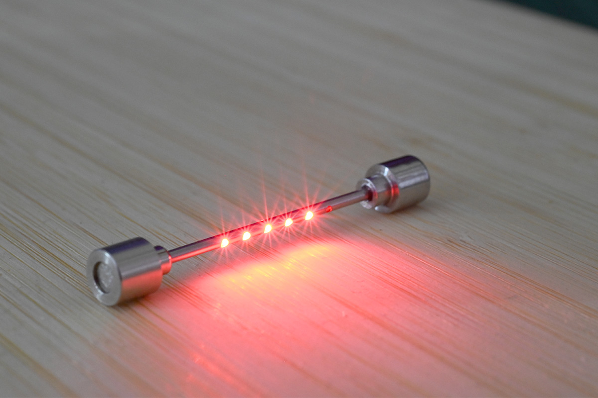
At this stage everything appeared to work perfectly, so I prepared some clear food-grade epoxy to fill the holes.
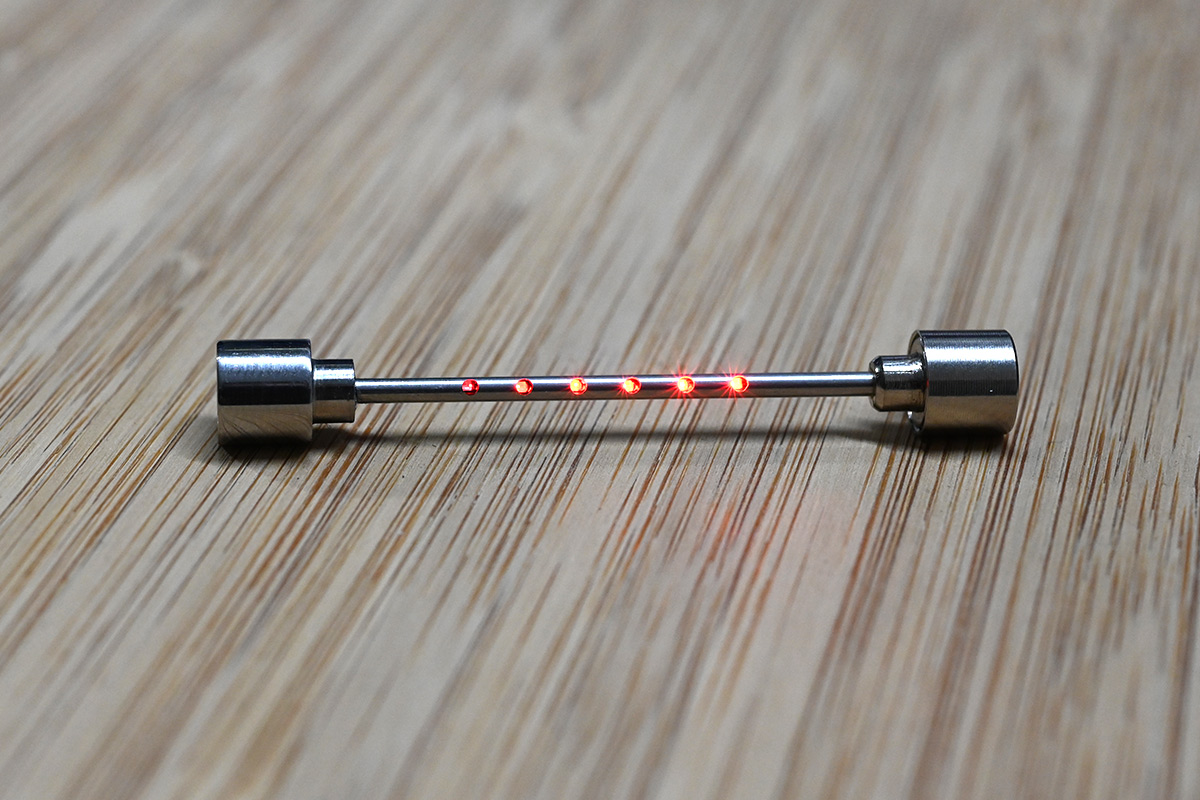
I assume the reader has already watched the video, but if not, spoilers: after potting the bar with clear epoxy, one of the LEDs stopped working. Luckily it's on the end, so it's not particularly obvious. As this happened after the epoxy cured, there's no way to repair it.
I'm not above building another one from scratch except that I'm currently between workshops. That, and I feel like it's been long enough that the next version should also be an improvement, not merely a second attempt.
End Cap
I originally planned to add one or more end caps to the design. These would connect into that programming header, which doubles as simply GPIO pins of the microcontroller, and offer various interfaces, such as a microphone or an IR receiver.I'm not saying it won't happen in the future but I didn't get round to it yet. And besides, the flashing pattern I settled on seems interesting enough for now.
Case
The case was modelled in OpenSCAD too. It's tricky to do fillets and chamfers, and I wasn't trying to make this look amazing or anything. In fact with the dead LED I wanted to wrap this up as quick as possible. But the case turned out great, it holds the device perfectly and you can just chuck it in a pocket without worrying.Here's an embeddiment. The scaffold is stored with the battery pack in the "off" position, i.e. pulled out a little.
The hinges are dressmaker's pins through just-barely-press-fit holes. It's stiff enough that the lid will stay at any angle.
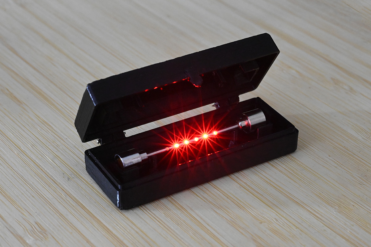
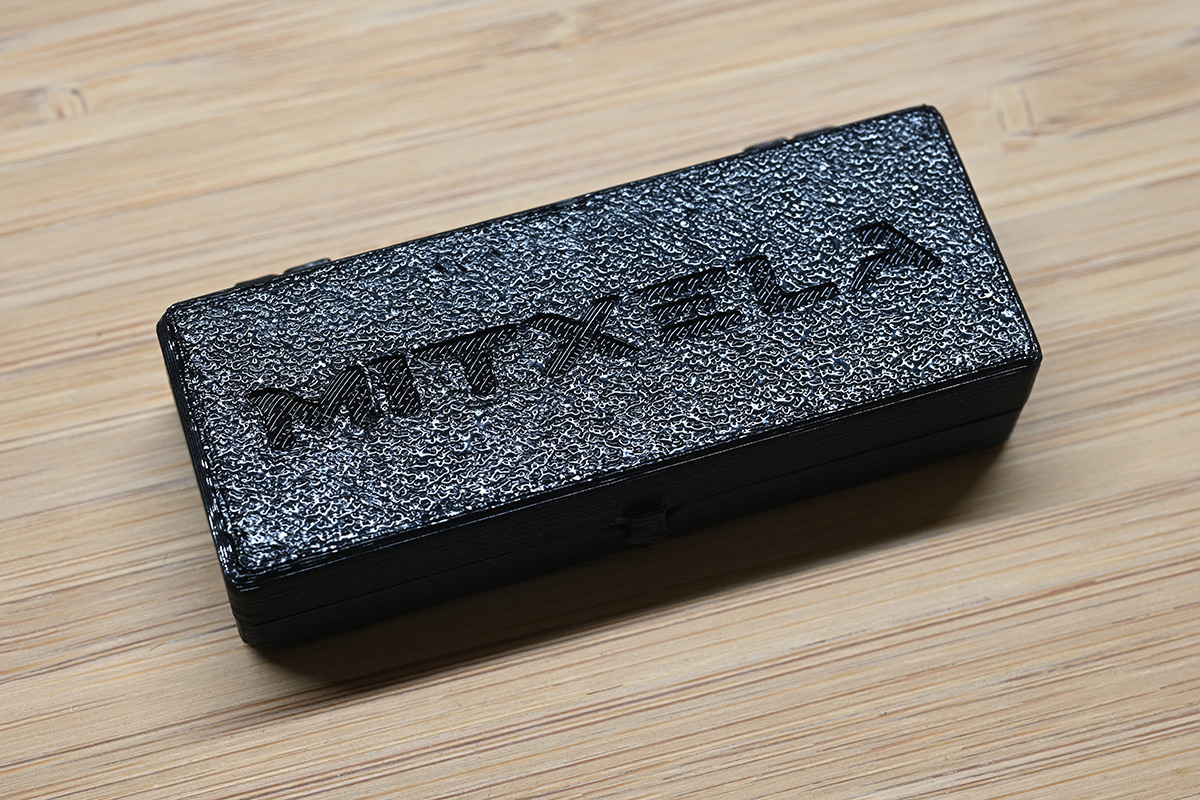
The texture on the lid is from the bed of the 3D printer. It helps parts adhere while they're printing, but it also adds a bit of interest to the end result.
Modelled
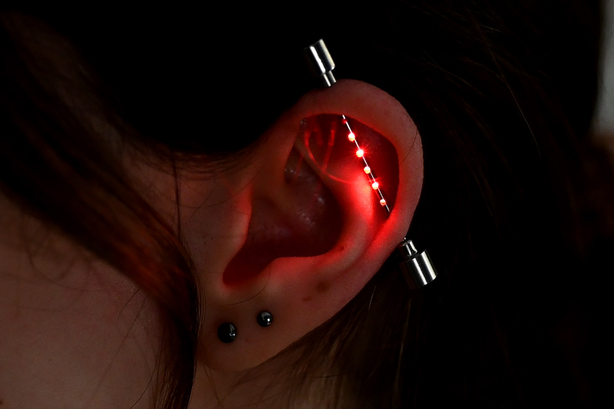
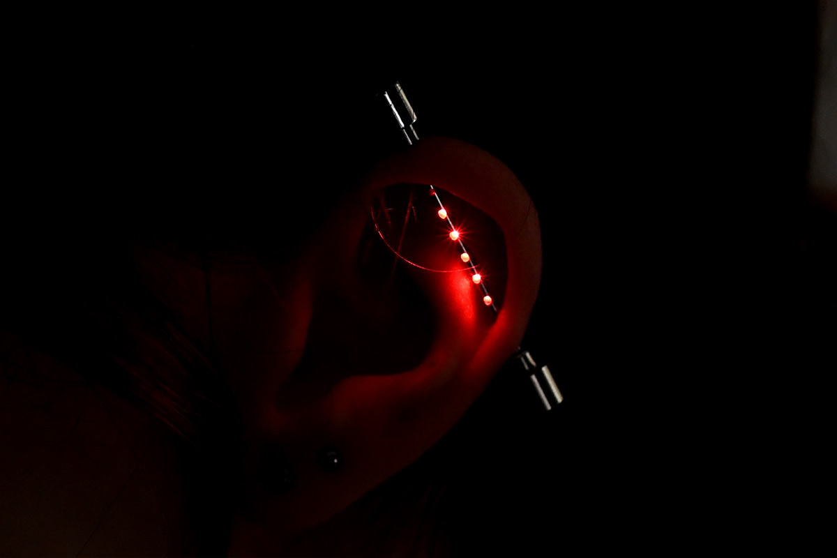
It's a while since I've had a living, breathing person pose for my macro lens. It is quite tricky to get the exposure right, usually my subjects are inanimate.
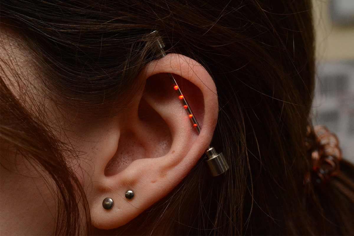
The flash does somewhat drown out the LEDs, makes it look a bit clinical.
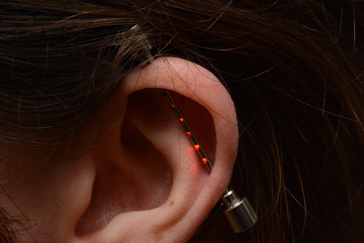
It's entirely possible I'll get some more pictures of the piercing being worn in future. It would be cool to do some long exposures with flash, so that the image is visible but the LEDs leave a trail.
Battery Life
I measured the current draw at just over 3mA. LR521 batteries have a capacity of about 10mA at best, which naively implies about 3 hours of battery life. However, the alkaline discharge curve is pretty steep and it's not clear at what voltage the chip will brown-out, it could potentially cut out well before the batteries are depleted.However, there's another battery in the same form factor called SR521, which is a silver-oxide battery. Not only does that give us about double the capacity, the discharge curve is much flatter so with those we should be good for at least five hours.
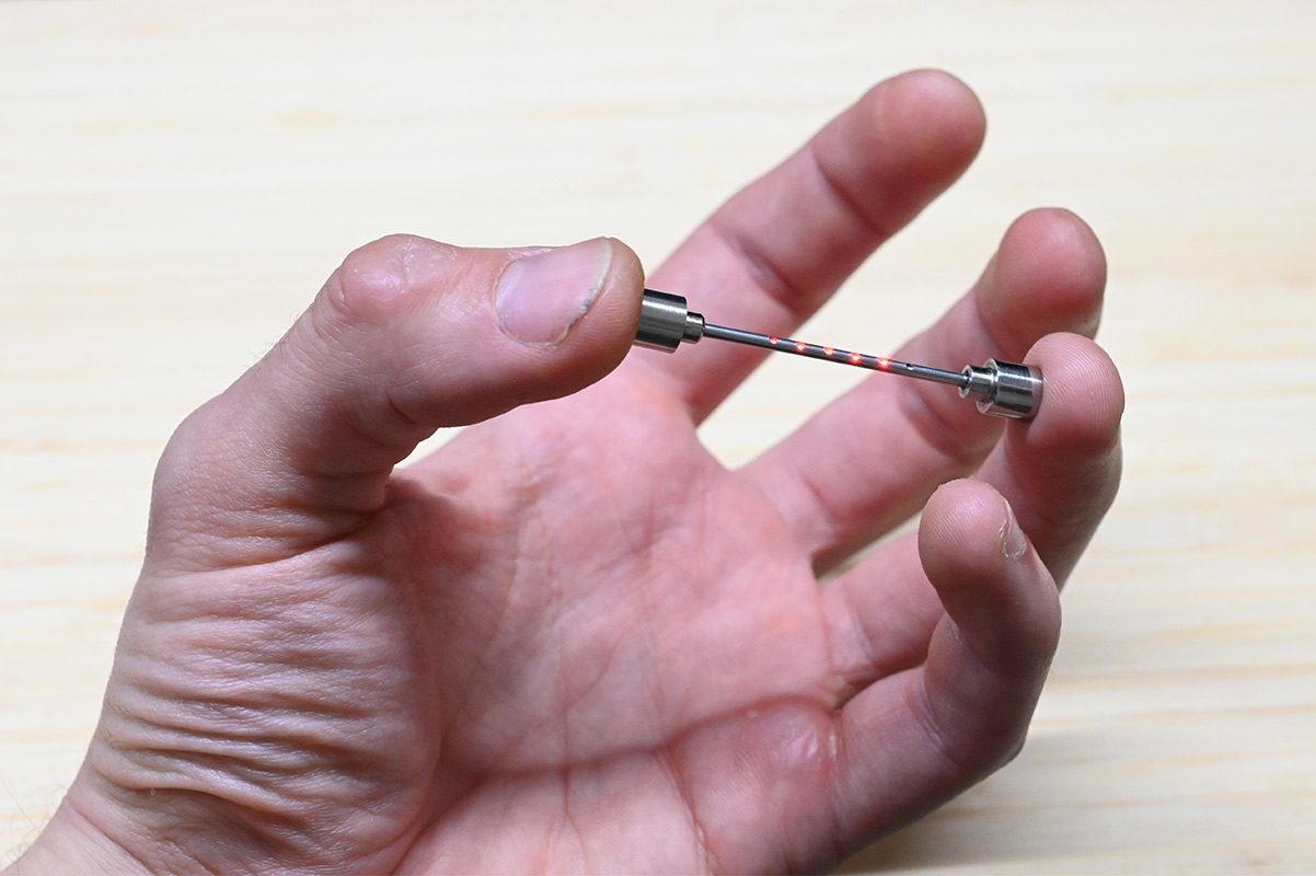
Changing the batteries is about as fiddly as it looks. Really, instead of machining that collet to be bigger, I should have just reduced the diameter of our bar near the end, so the regular battery holders from the cheap earrings could be fitted unmodified. In that case, it would only take a second to swap the whole battery pack, instead of having to unscrew things.
Conclusion
Overall, to my surprise, there really wasn't anything particularly challenging in this project, for the most part all the bits I expected to be difficult turned out fine. Evidently the next piercing will need to be smaller and use those 0201 LEDs.
I'm pretty pleased with the result. I was a bit disheartened when the LED died, as all of my joking about soldering things the hard way using the wrong equipment then sounds a bit pathetic. It's fine if you use terrible equipment and it works regardless, but if you use terrible equipment and it fails to work then you're just a fool.
However when I saw the thing being worn I had to admit that it looks really good.
If you would like to own one of these piercings, you simply can't. At least, it would be even harder for me to make and sell these than most of my inventions as the length has to be sized exactly to the wearer's ear. But, if you're totally loaded and you really want one, get in touch.
The source code for the ATtiny is here.