
Rumbler
23 Jun 2020Progress: Complete
This project is just for fun.
One of the worst bits about the pandemic – apart from all the illness and death of course – is that with everyone stuck at home, all the advantages of living within cycling distance of central London evaporate. For the price of a reasonable dwelling elsewhere, I'm trapped in a small flat with neighbours above, below, and to the side.
My neighbours are not exactly the silent type, and their incessant variety of distracting noises make it hard to focus and hard to sleep. Earplugs usually aren't enough. One technique, pioneered by the great Hunter S. Thompson, is switching your TV to some empty channel and turning up the static to drown everything else out. Unfortunately, since the switch to digital television, this technique has lost some of its efficacy.
An excellent substitute is to prepare an mp3 file of white noise, and play that on loop. If I'm honest, this works so well and is sufficiently customizable that there really isn't any reason to do anything further.
But for years, since the very first time I tried this, I've had a craving for a hardware noise generator. A little box that spits out real analog noise, with a couple of knobs to set the tonal qualities. The intensity of neighbour noise in the recent months, and an unexpectedly free evening, pushed me over the edge to finally build this pointless device.
Rednoise
White noise has a flat spectrum, but our ears don't have a flat response. Human hearing is a bit more like a parabola, very sensitive in the middle but less so at high and at low frequencies. The high frequencies aren't really a problem, because walls and windows attenuate high frequencies very well. Low frequencies are the main thing we want to drown out, the muffled sounds of next door's TV, domestic arguments, and so on.Pink noise and red noise have specific characteristics, but I don't care about the pedantry here. By "rednoise" I just mean white noise that's been lowpass filtered until it makes an aesthetic background rumble.
Analog fun ("fun")
Perhaps this project is just another excuse to play with op-amps.
Analog electronics is a lot like programming a computer. Except,
- there is no "undo" button
- there is no version control
- there is no ability to save your progress, except for taking a photograph, or tediously tracing out the schematic, which is prone to mistakes
- if something breaks, it's never clear if that's because of a change you made, or just a loose connection on the breadboard
- making mistakes means parts break, either spectacularly exploding, or worse, silently failing.
It's quite astonishing that analog engineers got anything done at all.
Both types of failures occurred this time. Putting 20 volts into a 16V-rated tantalum capacitor caused an immediate explosion. And miswiring the op-amp for just a few seconds burnt it out. Usually the smell is a giveaway, but this time I noticed the heat (I've a habit of checking the part temperatures religiously) and cut the power. Not fast enough to stop the part being toast, however.
Design
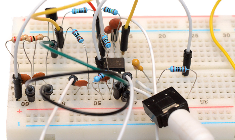
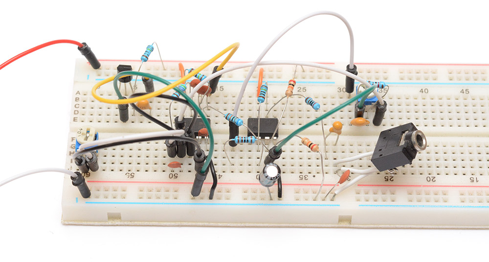
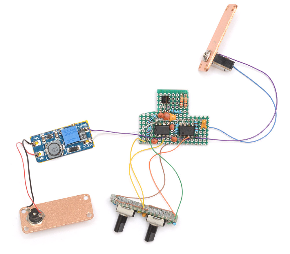
There are a myriad ways of producing white noise. Even a resistor is a source of relatively white noise. Many example circuits use a zener diode, but if you haven't got a suitable diode a simple NPN transistor can suffice. The base-emitter breakdown voltage is about 12V on a 2N2222. The collector can be left unconnected.To this we apply a huge amount of gain, then lowpass a few times, and gain again for volume control.
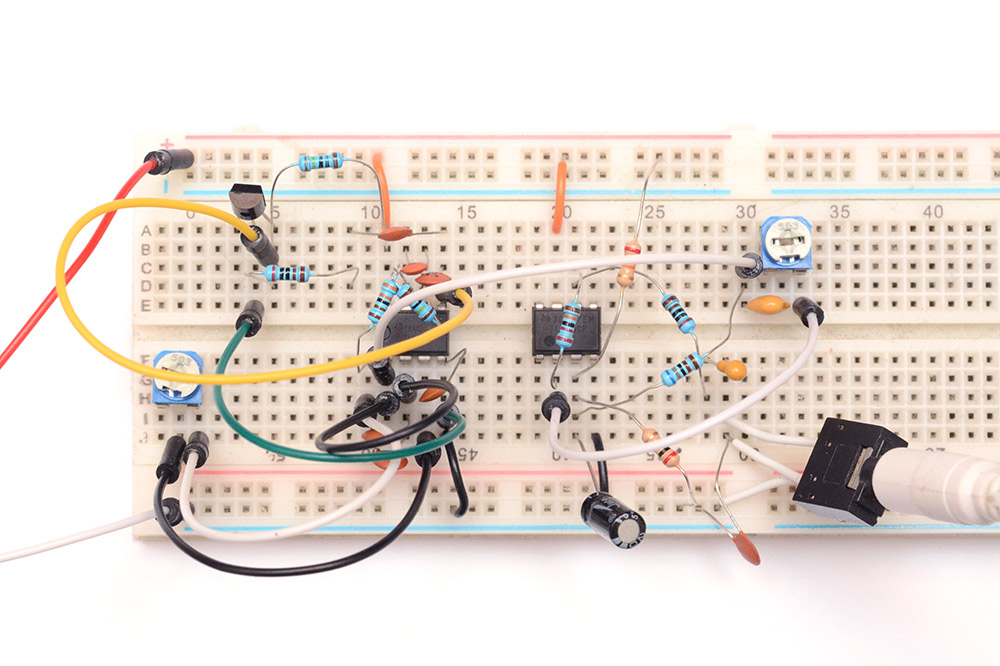
The chip on the left is an 072 (dual op amp) and the chip on the right is an 071. Using a quad op-amp or three single op-amps would have made remembering the pinouts simpler, but this is all I had to hand (at least after frying the first one).
Much time was spent fiddling with the values and the arrangement for lowpassing. A little bit of lowpass can be had for free by adding a small capacitor to the negative feedback of each amplifier. The main adjustable filter is of the Sallen-Key topology. The volume at this point was done by changing the gain of the final amplifier, and a final bit of lowpass was added by sticking a 100nF cap across the output to the speakers. That's a poor decision as it makes the cutoff depend on the input impedance of the speakers. The output stage changed a few more times before I was happy with it.
The sound output at this point was spot on, ranging from a deep rumble to a windy ocean splash. The volume pot would need to be logarithmic but apart from that the design is fine.
Leaving the breadboard
As always, the best small projects are the ones you finish quickly, and that means using only the parts you have in stock.I found a suitable enclosure. This aluminium box is about the right size, if a bit on the small side. In fact, the reason this was left over and not used in the project I bought it for, was that it's far too small to hold anything significant.
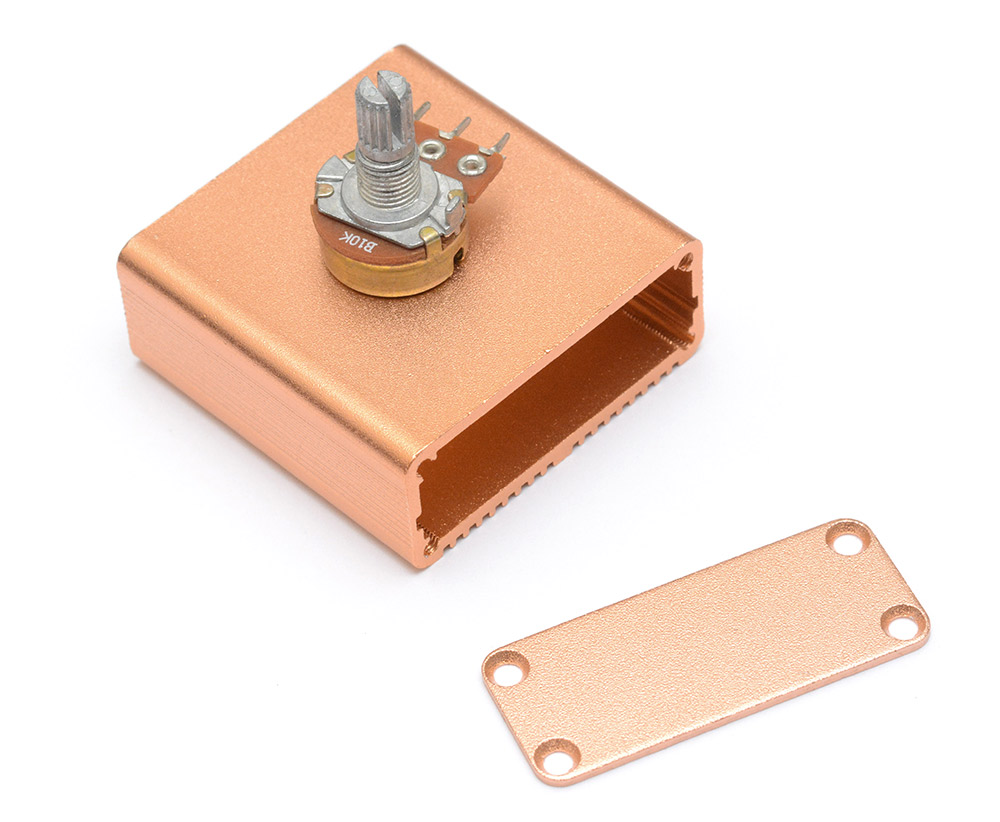
Never mind the fact that I've got no logarithmic pots in stock, even a regular panel-mount pot won't fit inside. It's too tall to be inserted on the top or bottom, and it's too wide to even consider on the other faces.
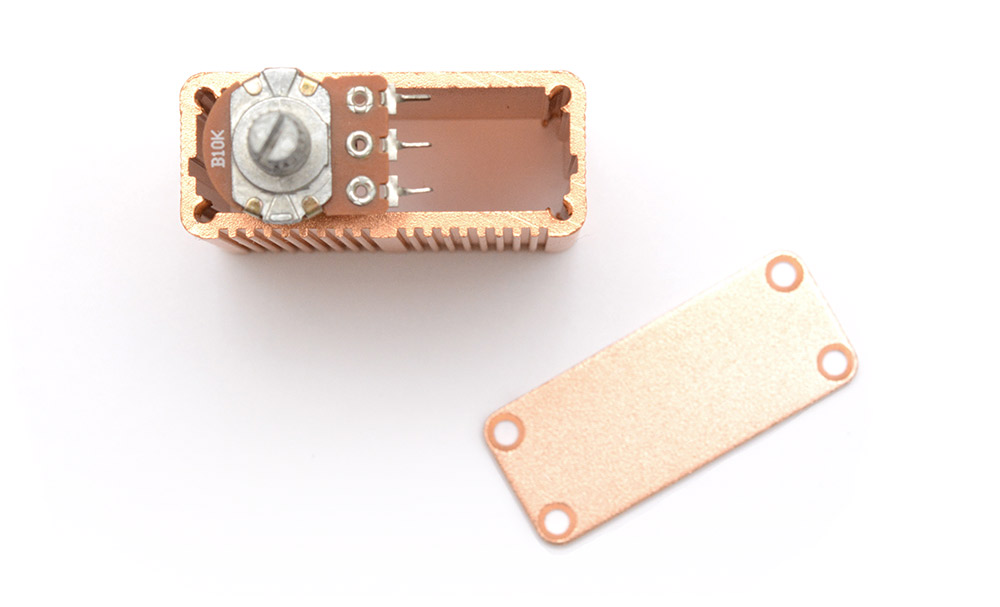
I have these little board-mounted ones that should do. It'll take some creative thinking to mount them, but I think we can manage it.
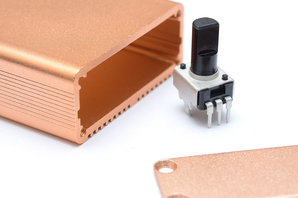
They're 100K, so I'll need to head back to the breadboard and change some other parts to compensate.
Another part we need to worry about is the power supply. I'd like the circuit to run from 5V so a boost converter will be needed. Here's a little step-up module that'll do.
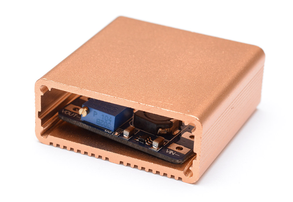
Looks like a comfortable fit, but when we add in the barrel jack, audio jack, potentiometers and the main circuit things are going to be very tight indeed.
Pot handling
There's a trick you can pull to convert a linear potentiometer into an approximately logarithmic one, by adding another resistor of about 10% the value in parallel. This won't work for adjusting the gain on an op-amp, though, since you'll end up with an anti-log curve if you add it into the negative feedback loop. You can cheat by adding more op-amps, but it's easiest to simply set the gain to a fixed amount and use the log-pot trick to attenuate the signal before it.
While we're at it, though the circuit works fine, I'm irked a bit by two small problems – the kind of issues that separate a cheap product from a premium one.
First is that the final gain stage is quite high, and additional noise can be heard. I know the whole device is a noise-maker, but the wrong kind of noise can ruin the pleasing effect. We don't want a fine hiss layered on top of our rumble, so it has to go. That 100n cap across the output does work, but it's best to set the characteristics in the feedback network, so it's more small caps we need to add there. As pointless as it sounds, I find it quite important that when you turn the volume knob to zero, you get zero sound output. I didn't quite manage that, but I got it quiet enough to not be noticeable.
The second issue is the effect of having a DC offset. Even though we block the DC on the output, having large DC offsets between stages causes an irritating ruffle noise as you twist the volume knob. Many people wouldn't care, but to me it's sufficient ruffling to tackle. The (desirable) noise starts off at the ~12V bias of the breakdown in the transistor. A DC-blocking capacitor can then pull this to a virtual ground at about 10V created by two resistors across the power rails. The volume pot attenuates against this virtual ground, then it's DC blocked again before heading to the output.
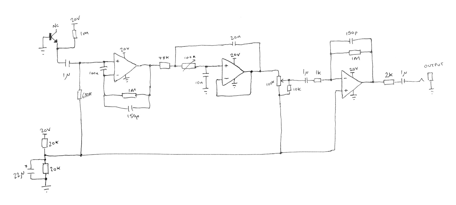
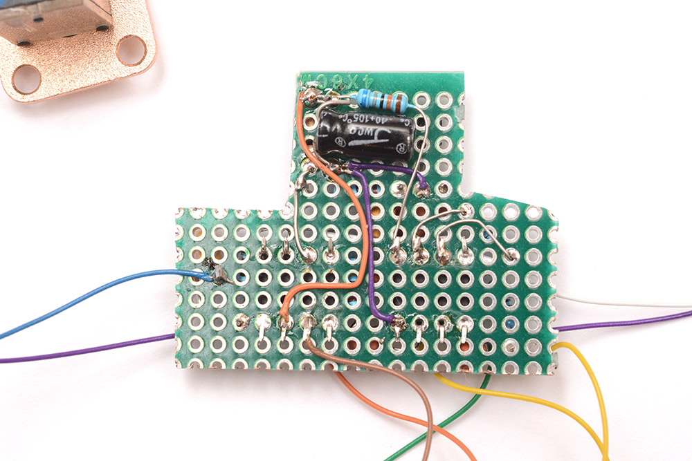
Before immortalizing our design on protoboard, I thought it shrewd to draw out a schematic of the design so far.
Assembly
I drilled a couple of holes in the case, and fitted the pots to protoboard after fettling down all the unnecessary bits. My idea was to have the main circuit board hold the pots fast against the enclosure. A quick mockup showed we'll have just enough room to pull this off.
Cutouts will be needed for the jacks of course. After sliding out the main board, the potentiometer board ("pot board") is free to be wiggled out for disassembly.
Some parts had to be added to the pot board, as I ran out of space on the main board. The wires joining the boards were carefully arranged so as not to interfere with the mounting method.
I added an extra capacitor to the step-up module, to suppress a faint buzz I was experiencing here. I may have overshot, since it now makes a squelch noise when you cut the power, but I can live with that. The module is switching well above audible frequencies, but there's definitely a hiss coming from it, which only appears when the main board's amplifiers are placed close to the module. I upped the capacitance on the final lowpass stage to compensate.
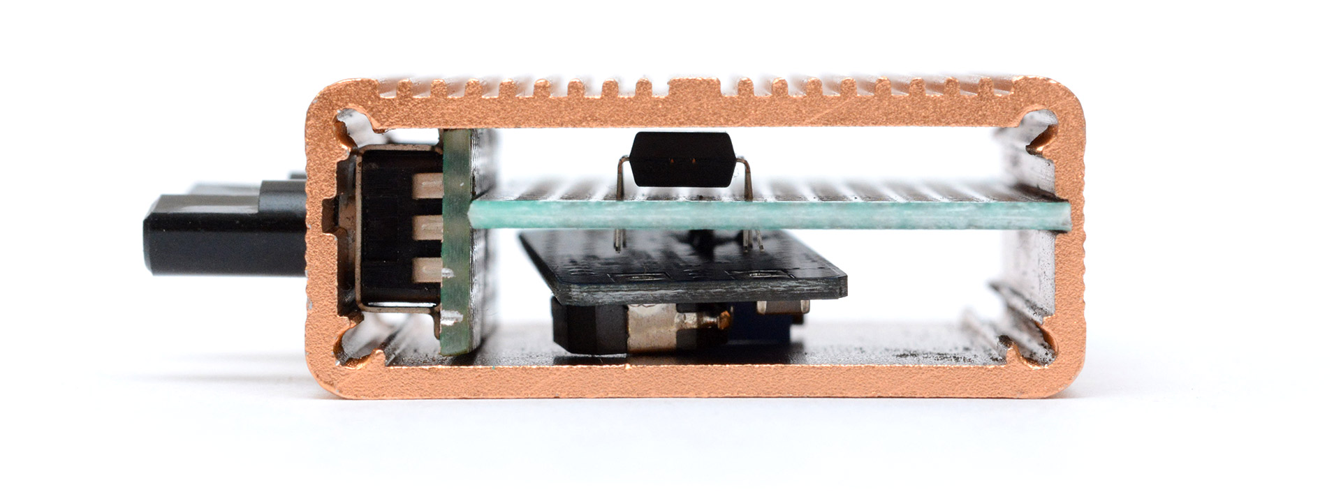
The underside of the main board had to be kept flat where it sits over the step-up module.
It's a bloody tight fit!
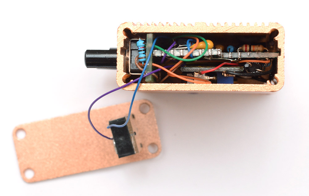
One last thing before we close it up. I made a simple grounding tab and scraped away some of the anodizing from the inside of the case, and wedged the tab between the boards and the case. You'd think a fully metal enclosure would function as a Faraday cage, but if it's not grounded the effect is basically nil.
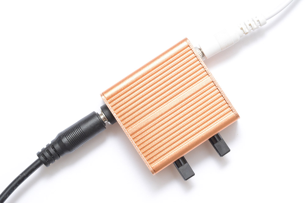
I hadn't planned to leave it knobless. I thought I had a sack of knobs somewhere (pot-knobs, not door-knobs) but they've evaded me. The only downside to the knobless look is that you can see the rough-cut edges of the holes in the enclosure.
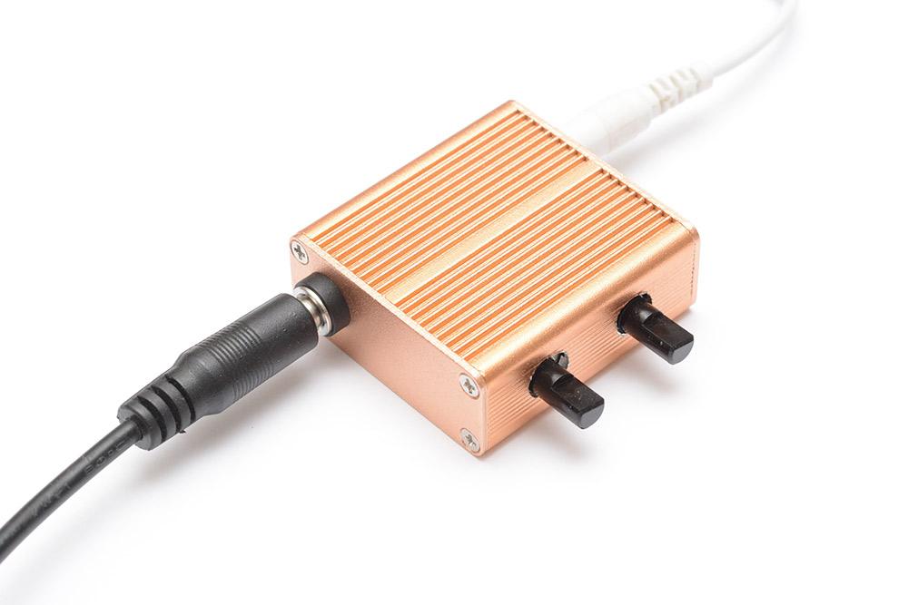
I'll order some more knobs.
Conclusion
It wouldn't hurt to give the reader a taste of the output. Here's a few seconds of me twisting the tone knob:
This whole project would have been so much easier, quicker, simpler and more customizable if I'd built it from an ATtiny with a pseudo-RNG and a digital lowpass. The circuit would have been basically one component, and we wouldn't have needed the step-up module. And different software could give it a vastly bigger range of rumble noises.
But even simpler than that, I could have stuck with the prepared mp3 file and not had to build any hardware at all.
Let's not forget one thing, however. As this ambient audio softly sends me to sleep, I can be safe in the knowledge that the rednoise rumble is cryptographically random.