
Hardware Reverse Oscilloscope 2
22 Sep 2023Progress: Complete
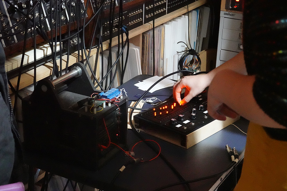
Time for another synthesizer. It's not for sale, just for fun. Here's a video where I demonstrate what the synth can do and talk a bit about it:
I met Dave at EMF. I was thoroughly impressed with his creations, but I was not prepared for the scale of his modular synthesizer. It's enormous! I also loved everything else in that room, not just the wall filled with other synthesizers, but even those sculptures on the right hand side. Upon closer inspection, they turn out to be synthesizers he's built.
Obviously when I visited I took a tiny box filled with synthesizers I'd made. One of them was the hardware reverse oscilloscope which felt like something that should be part of a bigger synth, but it was surprisingly tricky to get them to work together. I hadn't built anything with a CV input or output. It was also pointed out to me that the little device was essentially the same as one of the sequencer modules, sped up, which is true, excepting the output capacitor. But the software version of the reverse oscilloscope is quite different. Having multiple oscillators and a waveshaper changes everything.
I should explain a little about the software synth. I originally wrote it in about 2012, and then for years kept adding more and more features to it. The interface was incomprehensible, a stream of consciousness spattering of knobs and sliders. In early 2016 I decided to re-write the synth from scratch. I made a completely new interface, both more visually appealing and more intuitive. It was awesome, although I never completely finished it. I never released it, but you can hear it in some of my videos, including the stylophone business card. (There's a thousand comments on that video saying how cool it sounds, and not one person asked which synth it was connected to.)
I decided to build a new synth, something in-between the software and hardware scopes.
RScope mk. 2
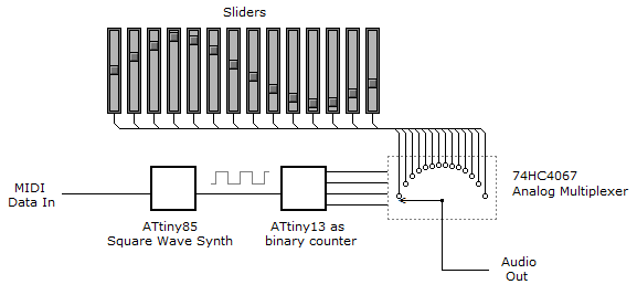
The original hardware reverse oscilloscope was an analog multiplexer, driven by a binary counter, driven by one of my tiny square-wave midi synths. I liked very much how it was just simple hardware – and the design meant it was completely free of aliasing.
I wanted this to be all hardware too, despite the fact that I wanted it to have a lot more features. We can do multiple oscillators, just have multiple multiplexers and buffer the signal where needed. We can do the interpolation, just about. It would need a filter with perfect pitch tracking, but that's not out of the question. The hardest part would be the waveshaper. The cyclic nature is equivalent to a modulo function, and doing a modulo of a voltage is most of the way towards building an ADC.
Due to unforeseen circumstances, I didn't have nearly as much time to work on this as I'd expected, but I still wanted to make it in time for the visit, even if that meant serious compromises. I find working towards casual deadlines like social events to be when I do some of my best work. I may have cut every corner, but at least the synth got finished. By far the biggest corner to cut was to avoid hardware as much as possible, do it all on a microcontroller. This introduces all kinds of other problems, but nothing we can't fix.
The waveshaper algorithm is something I came up with years ago, by accident. It's very easy to implement in DSP, but like all waveshapers, it's extremely prone to aliasing. The only way to avoid this is to pre-filter the signal, or oversample the waveshaper. Each doubling of the waveshaper samplerate gets us one more octave of headroom. I want all of the headroom. I set one of the pins on the DSP chip to go high when we start processing, and low when we finish, so the duty cycle tells us the load on the processor. Once the algorithm was written, I then just kept doubling the samplerate as many times as possible before we run out of processing power. It ended up as a 64x oversample, or six octaves of headroom.
Architecture
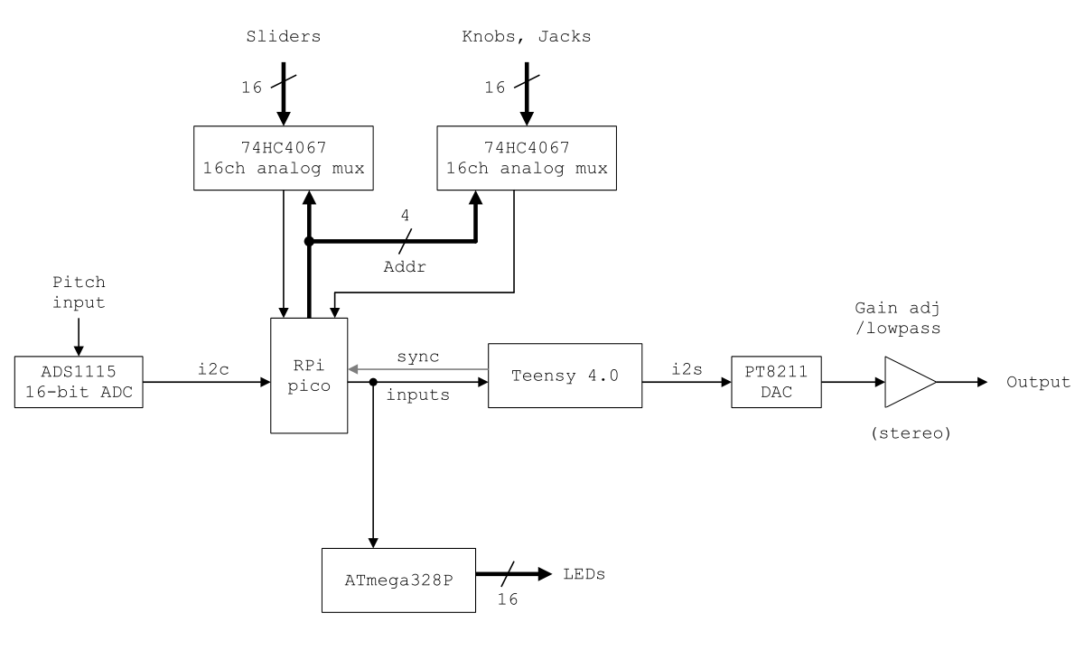
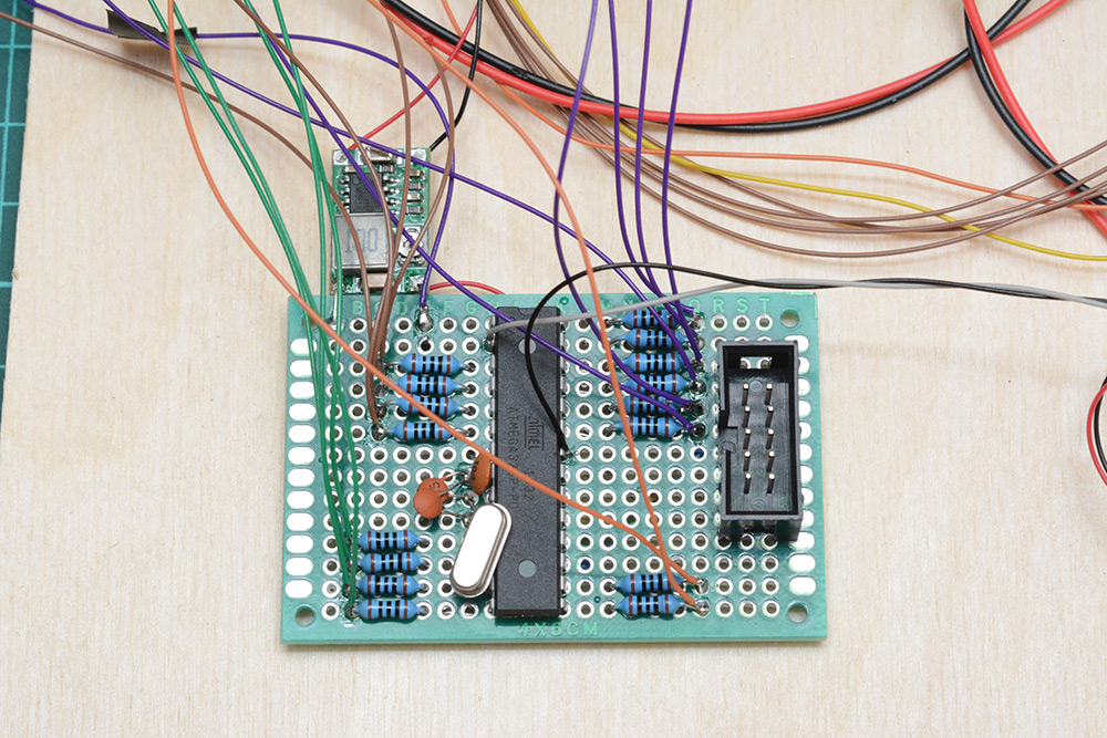
I've gotta stress that this wasn't particularly well thought out. I had ordered the Teensy 4.0 a while back to use on another project that never came about, but it's 600MHz which now sounded perfect for my waveshaper. For reasons that may not have entirely made sense, I thought it would be better to have the interface handled by a separate microcontroller, and keep the teensy for just audio processing. I went with the pico since they're cheap and available. And then, when I realised the pico doesn't have the current capability to run the LEDs directly, I was about to add some shift registers to drive them when I figured that in terms of soldering it was about the same as wiring up an atmega chip, which could then listen directly to the serial data, so we don't need to do anything extra on the other processors.
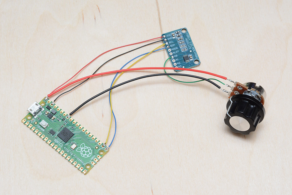
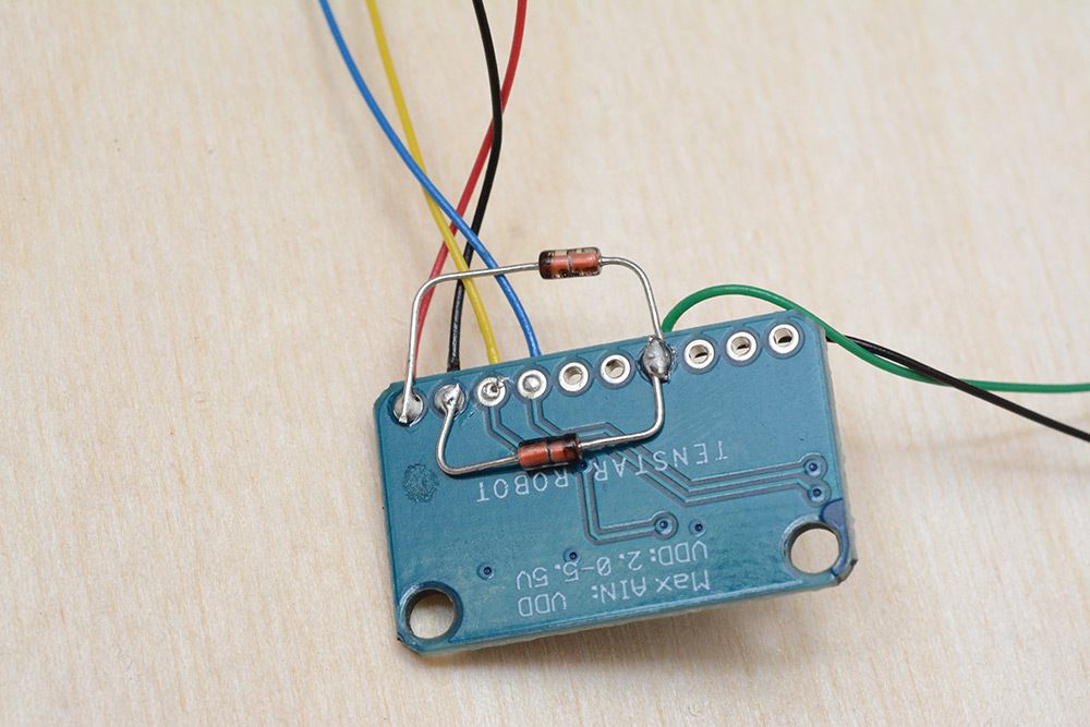
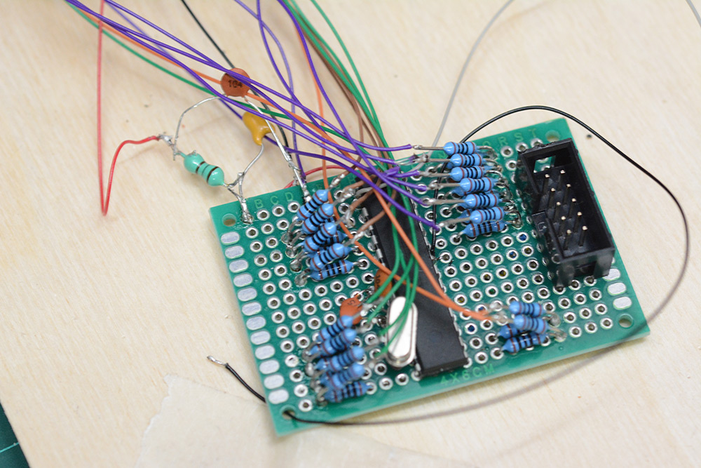
I started by wiring up the 16-bit ADC, which is read over i2c.
There was some concern about whether this would read the pitch fast enough. The audio buffer will be 128 samples, which at 44100Hz is about 2.9ms, or 344.5Hz. We need to report the complete state of the interface every 2.9ms, and that includes reading the pitch over i2c. I put the ADC into continuous-conversion mode at its second-highest samplerate of 475 samples per second. There may be some interference effects reading it at 345Hz, but if there were I didn't notice it.
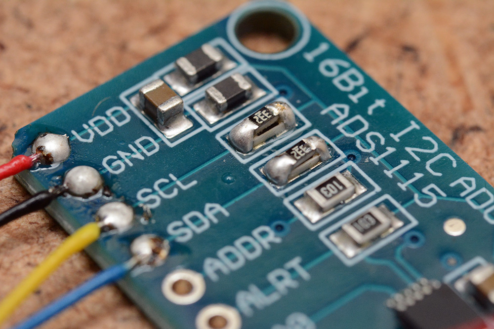
But to read it this quickly means fast i2c, and the pullup resistors on that breakout board weren't sufficient. I strengthened them by soldering extra resistors on top.
I wired the atmega up to drive the LEDs directly with 100ohm current-limiting resistors. The atmega was powered from a separate buck regulator, the idea being I could adjust the brightness by varying the voltage to the chip. It turns out that the different ports on the atmega have different current capabilities. I can't even remember if I wired them up as sinks or sources, but the LEDs on port C were noticeably dimmer. When I finished up the synth after the event, I added more current limiting resistors, and connected the atmega straight to the 5V supply (as part of my endless quest to reduce power supply noise).
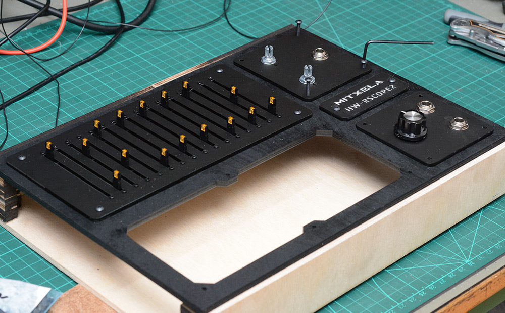
But I'm skipping ahead of myself. The biggest task was wiring up the sliders. The part number for the particular slider I'm using is PTL60-15O1-103B2. That's 60mm travel, orange LED, 10K resistance. I accidentally got the ones with a centre-detent, but that actually seems kind of handy for our waveform.
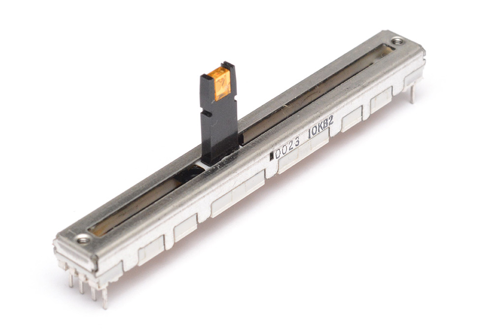
Incidentally, the LED is removable, you can just pull it out to replace it.
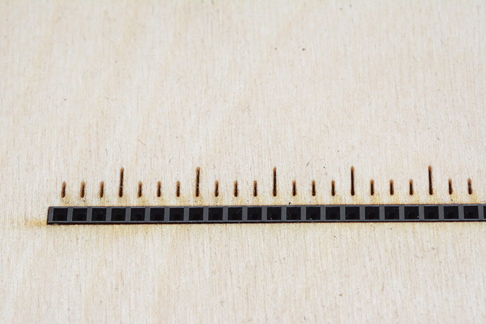
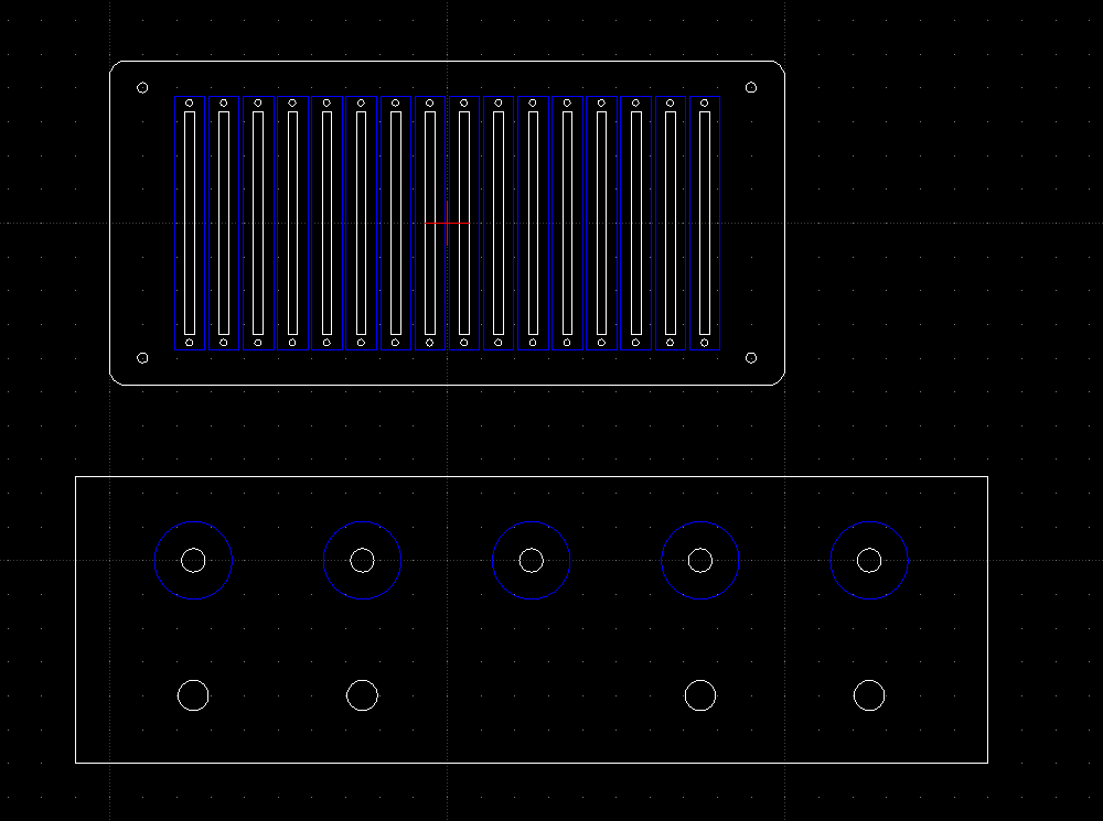
I thought I would be really clever about this, and socket all of them. I took some female header pins and laser-cut a frame to hold them, with laser marks for each group of four.
On the underside, I wired up one of the 16-channel multiplexers, along with a 3.3V linear regulator.
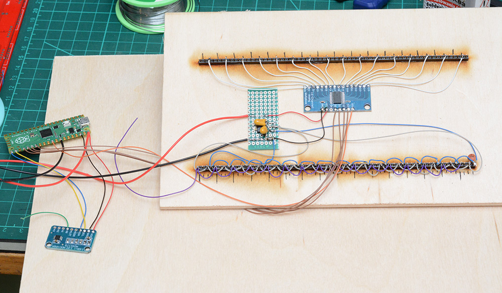
This arrangement let us hot-swap the sliders. In my haste, I wired up the sliders incorrectly the first time, and almost destroyed them. But worse than that, it soon became apparent that the header pins just weren't a good connection, most of them wobbled and made partial contact as you adjusted the slider. Eventually I conceded (very late in the day) that it just wasn't going to work, and I needed to solder to the sliders properly.
Luckily, I have a laser cutter, and the sliders have mounting holes. A few seconds of cutting gave me a mounting plate to transfer the sliders to, where I could then re-solder the connections on the back. Here's a test-cut in cardboard before the real thing:
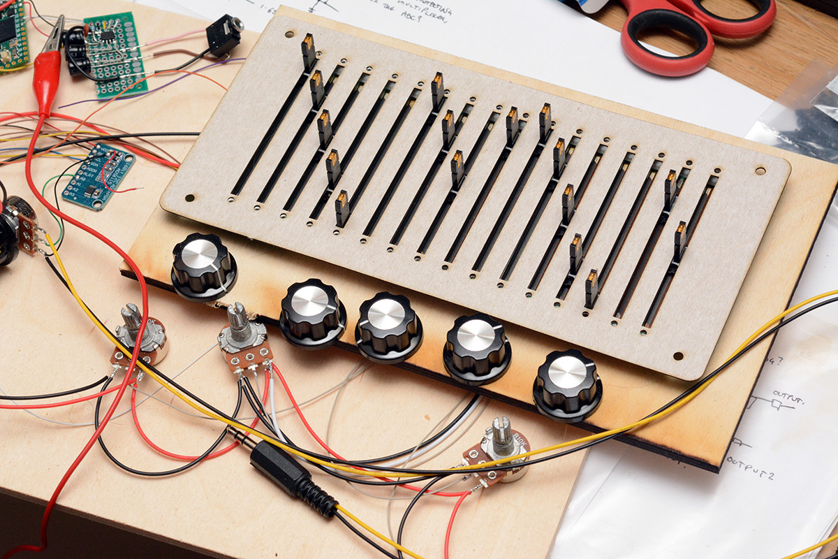
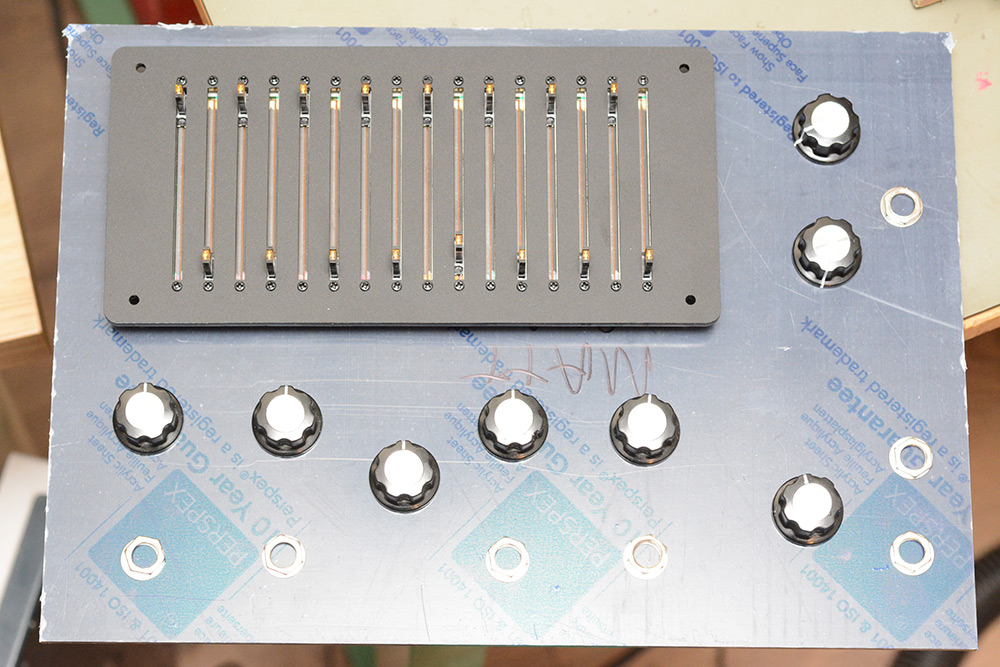
I ordered a load of M2 screws to mount them as a very last-minute thing. That actually held me up, and I couldn't do anything further on the sliders until they arrived. In the picture above, I've arranged some knobs to try and get an idea of where they'll go. I still wasn't sure how many knobs I was going to have.
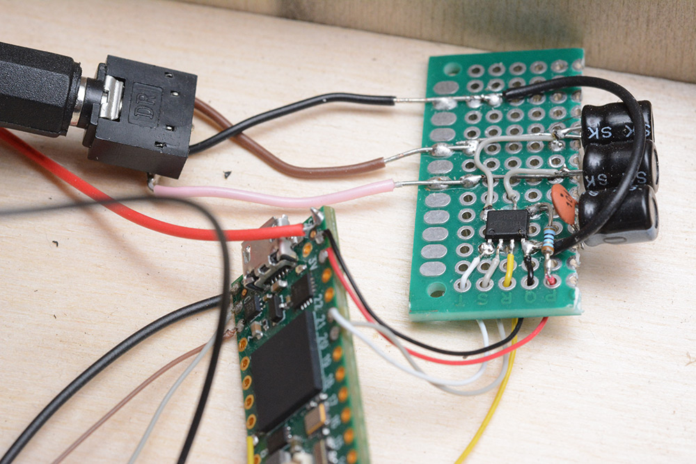
You can also see the audio output board, that's an I2S chip wired to the teensy. The line-level output was fine for testing, but even connecting it to my speakers would brown-out at higher volumes. It definitely needed amplification – but that could wait.
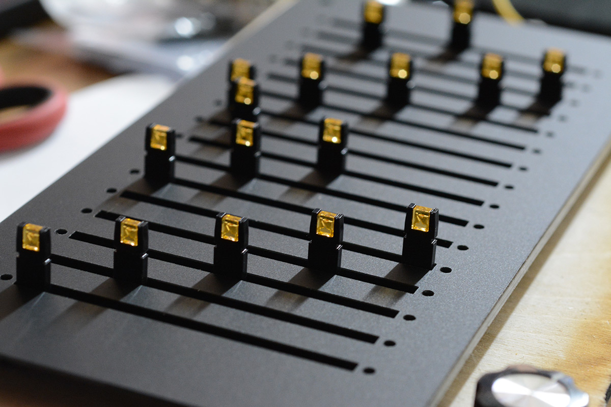
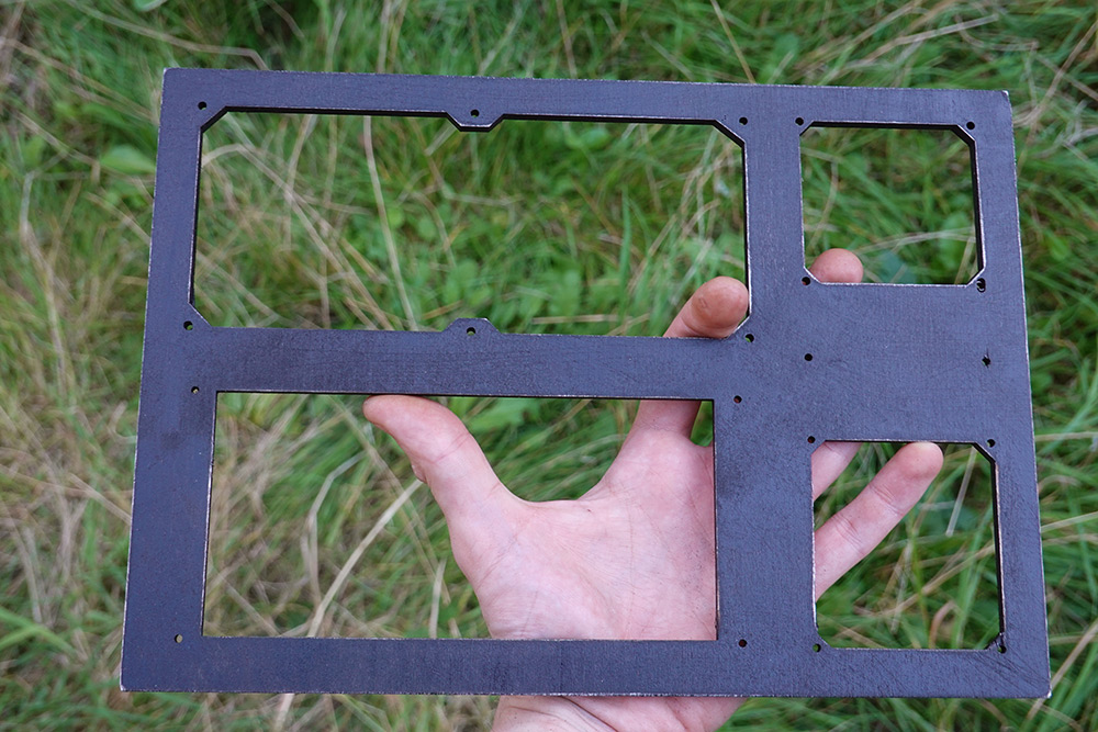
The real laser-cut panel was done in matt black acrylic. The result is absolutely gorgeous, I'm not sure why I've never used this material before.
CV inputs
Given the time pressure, the primary concern was how to build this with as little soldering as possible. Ordinarily there would be a huge amount of soldering. Even with the synth being digital, it's standard to buffer every input signal, which lets you add trimpots for offset and gain. I did some research, and it seems there isn't really a standard for the voltages in use. A normal gate signal might be 0 to 5V. An oscillator output might be -5V to +5V, and even a "standard" 1V/oct pitch CV could be 0 to 10V, or -3V to +8V, or -5V to +5V. To support everything, we're looking at a lot of opamps.None of this is standardised, but it's conventional to have 1kOhm output impedances on everything (except pitch signals, which may still have 1k but with the feedback tapped after the output resistor) and to have 100K inputs. And every input needs to cope with any possible voltage, and nothing should break when patch cables are connected in stupid ways, outputs to outputs and so on.
The fastest way to have CV inputs is to use 100K trimpots to drop the voltage to the right range, and use clamping diodes to protect the circuitry from voltages outside that range.
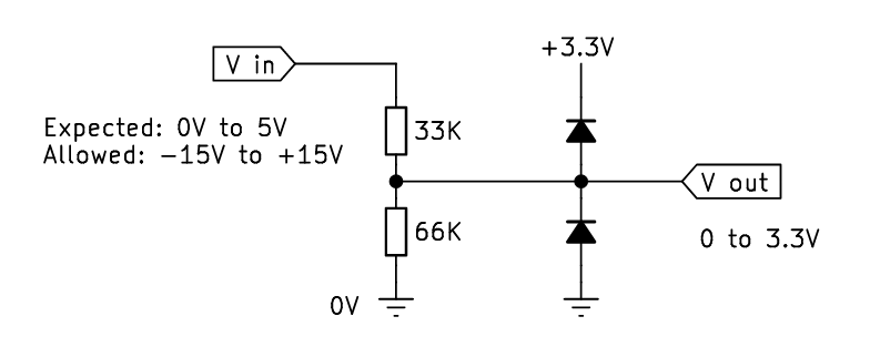
(Potentiometer shown as two resistors for clarity. 3.3V is 66% of 5V)
We've already got the 16-channel multiplexer for the sliders, so we may as well add another one to do the knobs and jacks. It can run from the same address lines, and we just feed both of them into the pico. The normal way to make a 32-mux is to use the enable pins as another address line, but I have a feeling we'll have less noise by using the onboard ADC mux to switch between them. Remember, we have to cycle through all 16 signals every 2.9ms, and some of them aren't particularly strong signals, coming from 100K pots. Best to maximise settling time if we can.
The original idea was to mix the knob and CV input in analog, but with 16 channels on the second mux regardless, there's no cost to scan them separately, and add them in software. The big problem I was worried about is whether the CV inputs are going to present negative voltages.
I'm not sure what most synth modules do regarding this. You could use a switched jack and have the CV input completely override the knob, but to me it makes sense to have the signals add. If we consider 0 to 5V as full-scale, then sending 1V should add a fifth of a rotation to the knob value. Similarly, sending -1V should subtract that from the knob value. But without op-amps, this is a very tricky thing to implement.
In the name of saving time, and considering the fact I don't even have any modular equipment to test it with (the keystep doesn't produce negative voltages at all), I just fitted the clamping dioides to ground and said it'll ignore negative voltages. But I did come up with a way of doing it without op-amps: we can scale and offset the signal in one step by wiring the trimpots to a non-zero voltage.
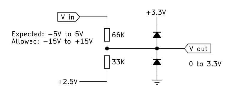
In the regular scenario (trimpot wired to ground) the voltage is scaled down, towards zero. Another way of thinking about this is that we take a weighted average between the signal, and a zero volt reference. If we change that reference to be non-zero, we can scale a full range of -5V to +5V into the range of 0V to 3.3V. Note the potentiometer is now at the 33% mark since peak-to-peak is 10V. We need to provide that 2.5V source, but a single regulator could be wired up to provide for all the inputs.
The only problem is that when you unplug the cable (Vin floating), the resting voltage is now no longer at ground. The pull is to 2.5V, but the centre voltage on the output should be 1.65V (half of 3.3).
The solution to this is to use switched jacks, so that while unplugged, the signal is shorted to ground. That would explicitly set our unplugged voltage to be at ground potential, so the ADC will read the same as when the cable is connected and providing zero. The only reason I didn't wire it up this way is that it didn't occur to me until right at the last moment, and I didn't have any switched jacks in stock.
Box
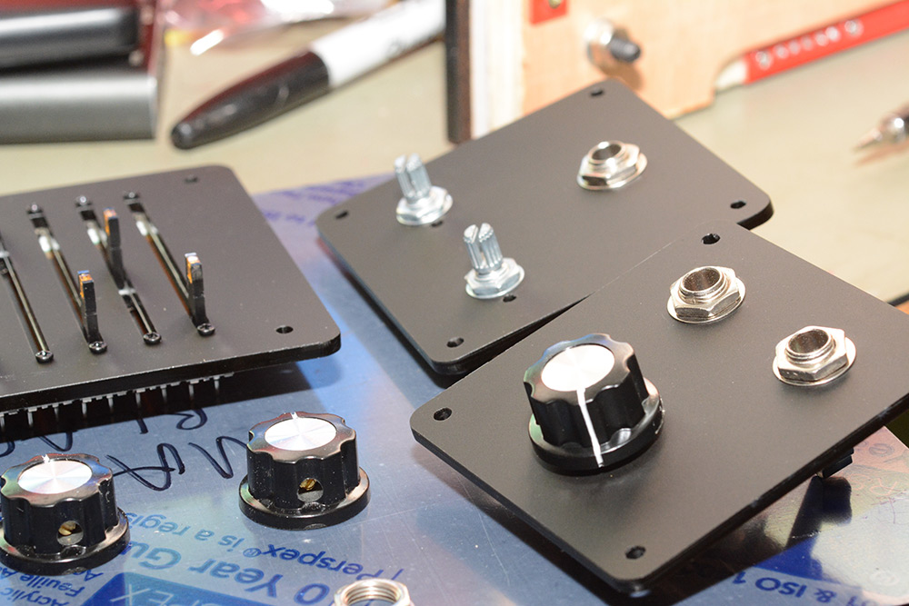
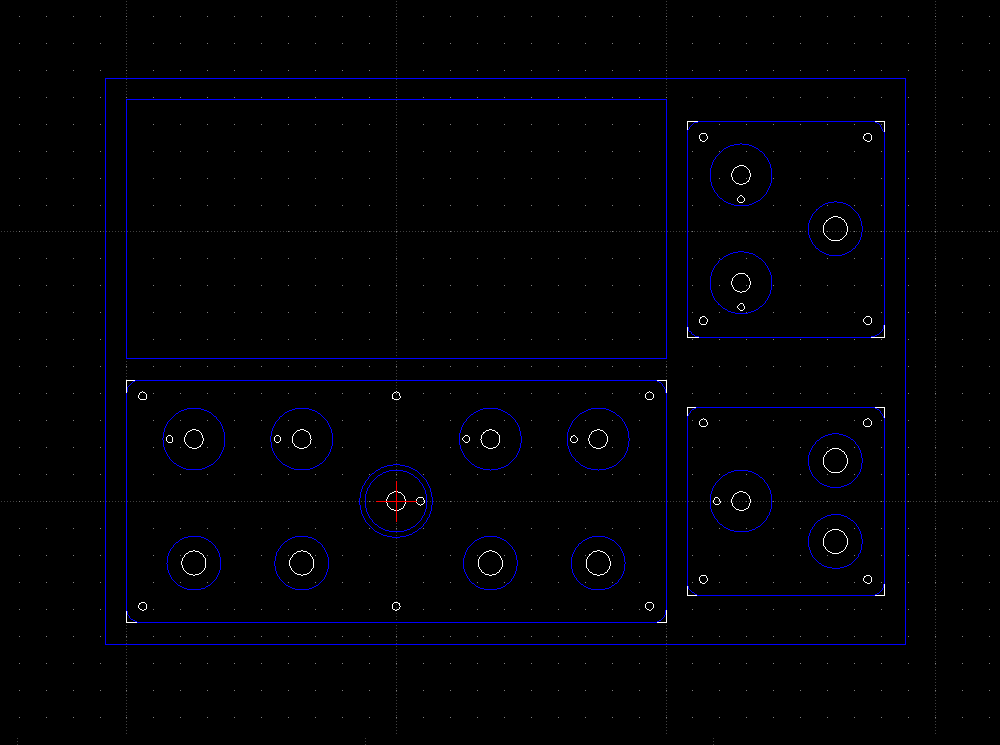
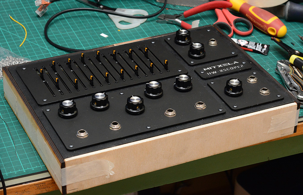
Three days before the visit, I still had essentially nothing to show. When I laser-cut the panels and glued the box together, suddenly I had a synthesizer. It didn't do anything yet, but it looked great!Part of the reason I cut the panels out separately is that it let me delay the decision on the final number and location of the knobs until the very last moment. Here's me mocking up the arrangement I eventually rolled with:
I was confident enough to cut out the input and output panels at this point.
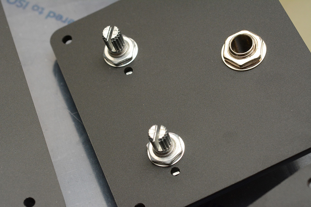
I love how quickly it came together. It's so easy to try a design, in cardboard if needed, and cut it out again to iterate. Nothing compares! Adding the little holes to stop the pots rotating took seconds.
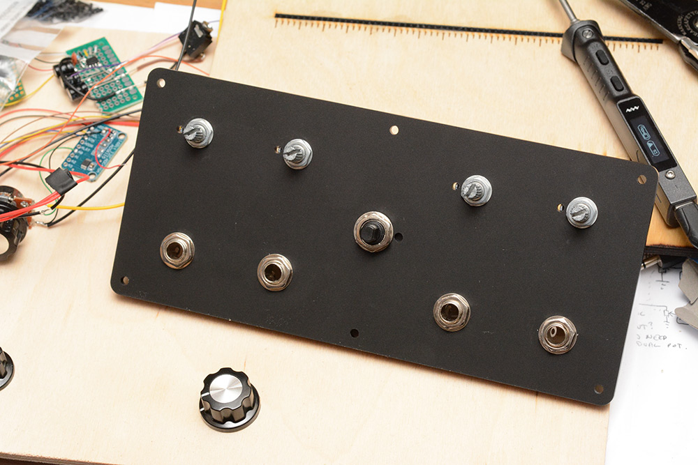
Much, much later I made my mind up about the main parameters. I don't know if there's a standard spacing for knobs and stuff in this format, I just went with what looked nice. I particularly wanted to leave enough room around the knobs to label the positions, which is something I didn't get around to doing.
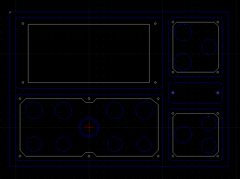
Most of the initial mocking up was done by dragging things around in photoshop, but I also did some 2D design in LibreCAD. Never used it before, I just googled for open source 2D CAD and it came up.
Seems to work well enough, at least, it's far less glitchy than moshidraw, which is unable to even do copy-paste correctly.
Part of the reason I worried about this is that I was torn between the aesthetic of an oscilloscope (which usually places the waveform at the top left, the timebase to the right of it) and the general feeling of most audio equipment, that signals start in the top left and move downwards and rightwards. Another concern, which only occured to me fairly late in the process, is that when things are plugged into the jacks, the cables will get in the way of anything below them. That's a strong reason to put all the jacks at the very bottom, or at least, along the edges.
I considered having the pitch input panel be on the top left, basically swapping it with the waveform, but my gut told me that was the wrong decision. It wouldn't feel like a scope.
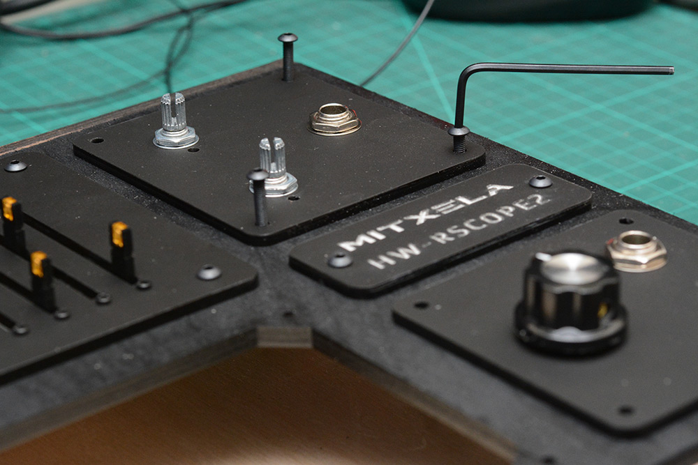
I filled the bonus space with a logo plaque. Despite the time pressure this was some light relief. Haha. Relief.
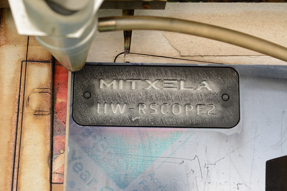
You have to peel away the protective film before etching or it melts it all together into a mess. The residue wipes right off, which is a shame because I think it looks kind of cool.
The surrounding support panel was made from A4 plywood, laser-cut and spray painted black.
Two coats of paint with sanding in between. Even when we're in a hurry. You can tell I was rushed because it's upside down. I've painted the wrong side. D'oh!
For an unrelated project I have a ton of these black M3 button head bolts. No one will notice if I steal a handful.
The plywood's soft enough (and the laser holes sized exactly) that we can pretend the bolts are self-tapping.
The rest of the wooden box did not receive quite so much care and attention.
A funny coincidence, A4 in landscape is 210mm high. Using 5mm plywood top and bottom takes us to 220mm, which is almost exactly 5U. That was completely unplanned.
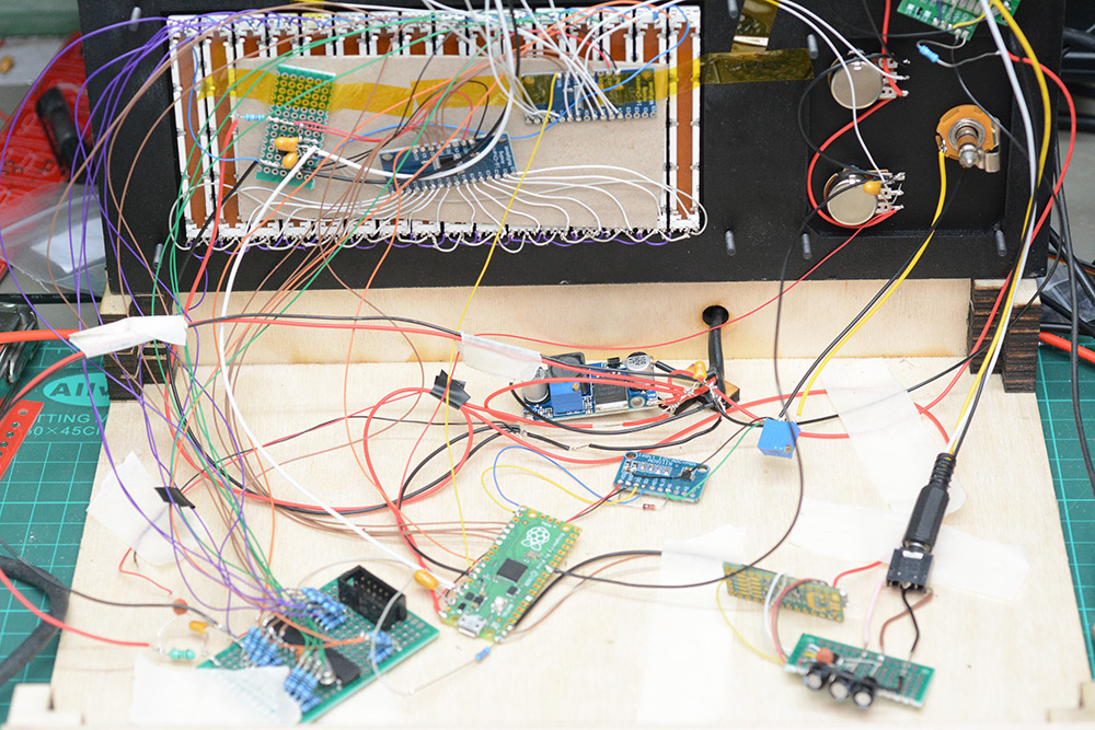
Boxing the circuits
I didn't bother to re-solder the four knobs I'd wired up on the desk, so we ended up with a twisted mess of wires there.
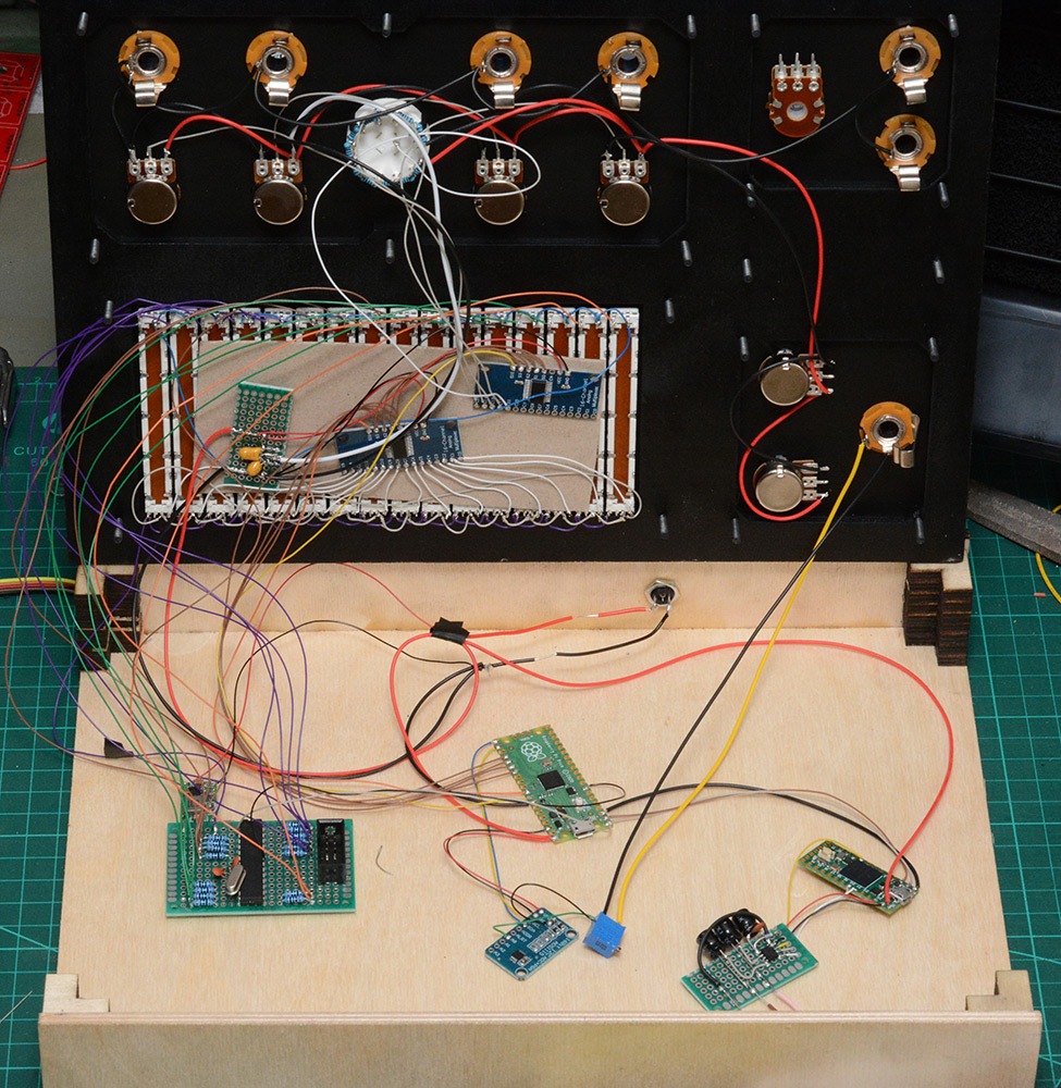
The rotary switch for oscillator config was at this point theoretical, but rather than adding more logic to read the state of it I just soldered resistors between each leg turning it into a stepped attenuator. We can then connect it up to the multiplexer and read it the same as any other knob. The rotary switch has a method to adjust the number of steps, I set it to seven, which gives us a middle position, and three clicks in either direction. But the resistors go all the way round just in case I changed my mind.
The multiplexers are now stuck onto a piece of card with double sided tape. This is substantially worse than the original arrangement where they were stuck to the plywood, but I didn't have time to fiddle with it now. The tape quickly lost its stickiness.
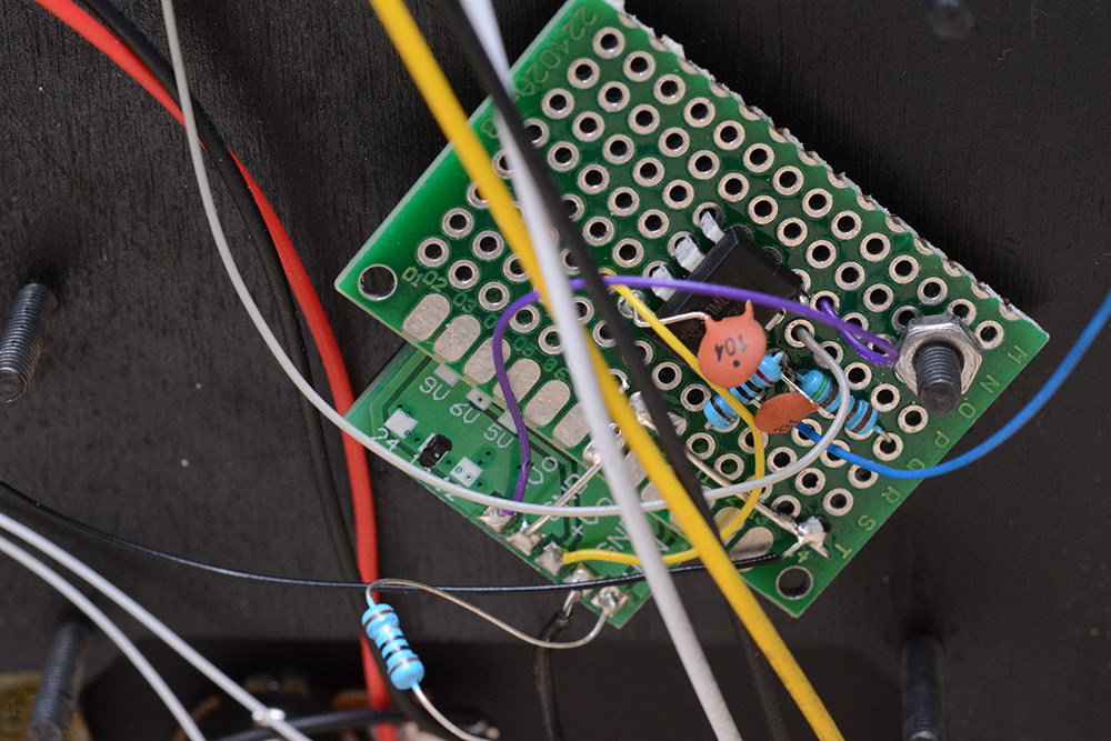
The blue trimpot at the ADC is volt-per-octave adjust, which seemed to weirdly depend on the power supply despite supposedly having a 4.096V reference. The synth would power up when I connect a USB cable to the teensy or pico, but the tuning would be off compared to when powered by an external 5V. In future I think I'll mount important trimpots like this one to be accessible from the outside, it was really inconvenient to open up the case to adjust it.
Clamping diodes were fitted to the ADC to protect it. These are schottky diodes for minimum drop.
Underside of the LED board, nothing fancy. I fitted a crystal to the ATmega because I knew there'd be problems without it. The serial data it needs to listen in on is 250kBaud. I chose that rate as the slowest we could go and still transfer all 33 control values within the 2.9ms window. I just know that the ATmega on its RC oscillator would have choked on it.
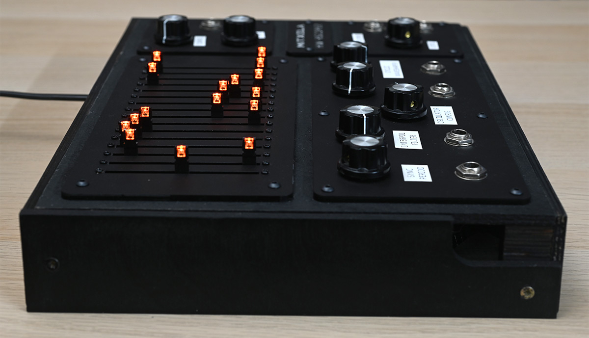
The original plan was to have a stepped input for the wave period, snapping to each slider, but then I realised how much more useful having a continuous control would be. To that end, I wanted the LEDs to smoothly illuminate: half a slider is used, the last LED should be half brightness. I didn't get a chance to do it though. By the time I came to programming the ATmega I was in the final few hours, so only the most basic illumination got implemented.
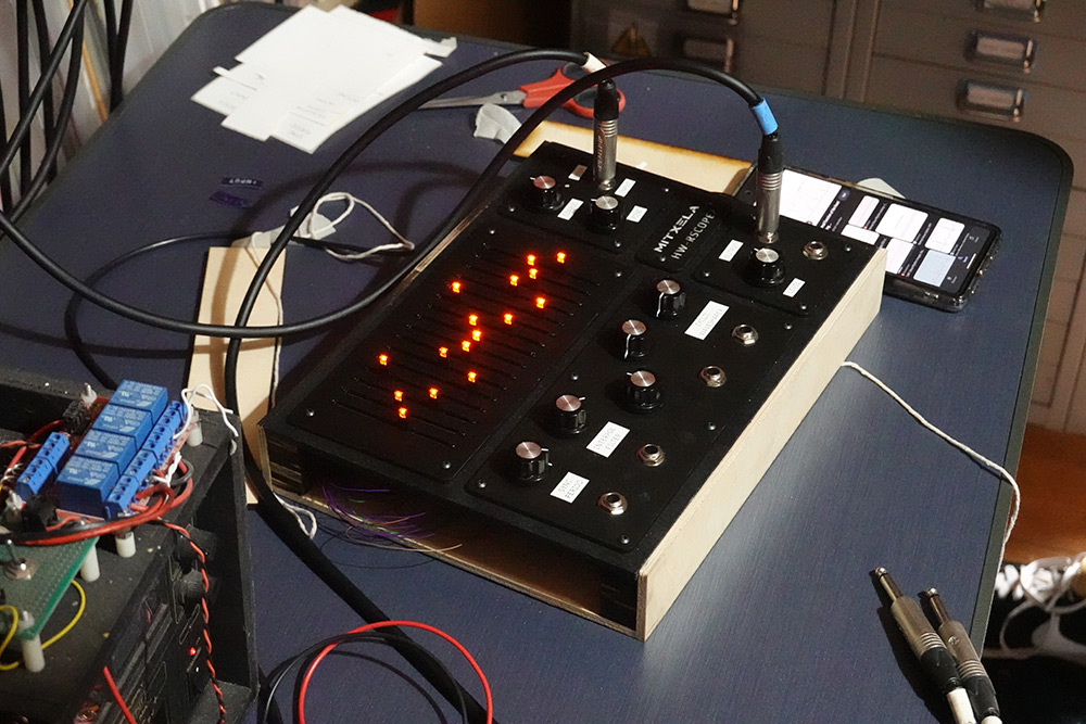
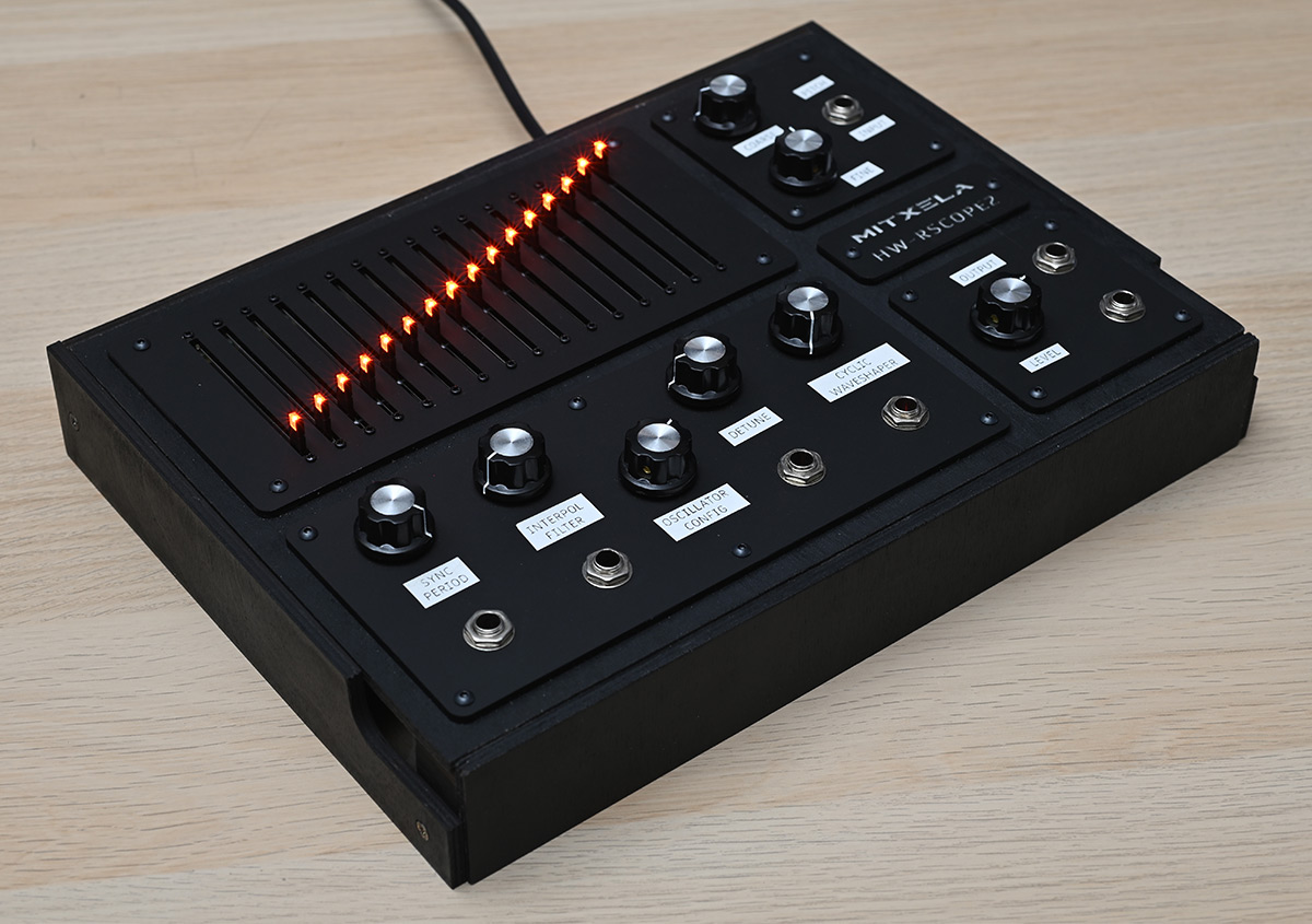
We gotta have it illuminated though. That's a core feature of the product.
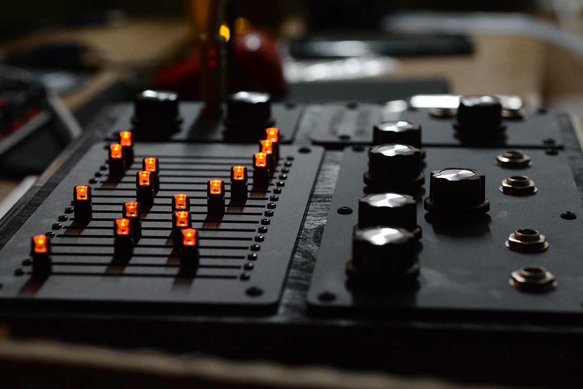
The matt black acrylic on the black textured plywood really does it for me.
Here's the state of the synth as I took it with me. The box wasn't painted and the sides are held on with tape. The box is entirely built from superglue and laser cut bits of plywood, which is a very fast assembly technique. But I didn't want to glue the sides on yet as it would make development very difficult, and at this point I still hadn't finished the software. Hence, tape.
Naturally the original idea was to laser-etch the labels and markings onto the panels but I didn't have time. Another nice box-related idea would be to make the top panel hinged, with a latch.
Pico firmware
The pico has a very simple job, to just cycle through the inputs and spit them out over the serial connection. The hardware UART has a 32-byte FIFO which makes this job incredibly easy, as we basically don't need to worry about timings, we can read the inputs and send them as we go. The total message will be a little longer than 32 bytes, the knobs and sliders will be sent as 8-bit values, then there's the pitch input as a 16-bit value and some kind of header too.I went with 8-bit values for the knobs mostly because the supposedly 12-bit ADC on the pico was very noisy. It seemed fine originally but as more of the synth came together that noise got worse. It may have something to do with the terribly messy wiring, or the power supply arrangement. There are various techniques you can use to improve the Pico ADC performance, such as putting the SMPS into PWM mode (made no difference), fitting a 3.0V reference (I didn't have anything to hand) or replacing the SMPS with a linear regulator (I did that later, to not much effect). The strange thing is that the external 16-bit ADC was absolutely rock solid, which suggests that it wasn't power supply noise per se. But the noise did depend on the number of LEDs illuminated, which suggests power supply issues, or a ground loop.
Anyway the noise will always be present to some degree, and so the plan was always to add hysteresis. We sample the input at the highest resolution, then compare it to the previous value, and only update the output if the absolute difference between the present and previous values is more than a tolerance. The works very well, so long as the hysteresis is more than the noise level.
The only other thing we need to do on the Pico is synchronise the messages. I originally had it continuously reading and sending, but it's better to align this to the buffer fills on the Teensy. This is as simple as sending a single byte from the teensy once per buffer fill, which keeps the two chips aligned.
The ATmega listens in on the serial. One thing to mention is that since we're adding the CV input and knob in software, that means the ATmega has to listen for two values and add them to get the effective number of LEDs to light up. That's fine, I went with putting the lower eight inputs as knobs, and the upper eight inputs as CV inputs corresponding to them.
Teensy and DSP
The Teensy Audio stuff seems very well thought-out. I'd like to have a proper play with it in future. I didn't even realise there was a Teensy Audio library when I soldered this up, I just wanted that raw processing power. The PT8211 DAC is one of the recommended i2s output codecs that the audio library supports.There's a cool GUI they've made that generates code for you, although the generated code is actually incredibly short, it's just a list of connections between things. In this case though, I don't want any of those modules, I know exactly what samples I want to generate. I made the simplest possible "sine wave to i2s output" and then copied the sine wave code into the program, modified it to just let me send samples to the DAC.
The main loop of the program just receives serial data and chucks it into arrays for the audio generation to use. The audio generation works like this:
- We first construct a wavetable from the sliders. This involves interpolation and filtering based on the parameters.
- We run our oscillators at the calculated pitches. These need to resample the wavetable. Since we need oversampling anyway, I made the oversampling high enough and the wavetable small enough that the oscillators only ever need to expand the wavetable (lower the pitch). This is done with a linear interpolation, and won't be subject to aliasing. All of the difficulty in wavetable stuff comes from increasing the pitch.
- The combined oscillator output is sent through the waveshaper.
- The output is downsampled to 44.1kHz and sent to the DAC.
All of the controls are quantised by the buffer (and the pico only sending updates at 2.9ms intervals) which means we need to interpolate everything. Without it, there will be clicking discontinuities as things are adjusted.
The pitch changes naturally need to be smooth, although at 128 samples a small discontinuity in pitch is barely discernable. It can only be heard when there's large swooping portamento. We don't need to recalculate pitch each sample, we just calculate it at the buffer boundaries and linearly interpolate.
The waveshaper control is just adjusted by setting the input gain. A sudden jump in gain will lead to a click, so again we need to interpolate. But more than that, even moving a slider leads to a sudden change in the wavetable. Similarly moving the Sync Period knob will potentially lead to significant discontinuities. Generating the wave table is computationally intensive, we couldn't possibly re-generate it every sample. It's surprisingly simple to interpolate the wavetables though. Generate a new wavetable, generate a table of the differences between each table, and for each sample sum one onto the other. It's pretty costly, but we've got the processing power, and getting rid of crackles and clicks is so important to make the synth feel natural. Organic.
One problem is that we're working only with single-precision floats. That wavetable interpolation has a risk of becoming unstable, with the diff values being inaccurate. I didn't investigate to see if this was a real problem or just an imagined one, but it's easy enough to deal with, just replace the interpolated table with the correct values at the end of the buffer. If nothing's changed, the following diff table will be all zeros.
A lot of what I wanted to achieve was in making the knobs feel intuitive. All of them are based on clockwise being "more" – more hamonics, more noise, coarser and harsher. Widdershins means smoother and softer. The interpolation knob consists of multiple sections, applying different things, but they're blended together in a way that feels natural. The waveshaper's lowest region fades it out into a linear mapping. Ordinarily turning the waveshaper to zero would give you zero output, whereas we just want zero effect.
I'm quite happy with how that all turned out. There is something to be said about building hardware control interfaces, where every extra knob costs you the time and effort of wiring it up. It really forces you to rethink the interface into a simpler form.
Output amplifier
The PT8211 DAC has a line-level output without much drive capability. We need to boost the output to get to the modular synth type of range (perhaps as much as 10V peak-to-peak?) and to stop it browning out on low impedance loads.
The datasheet suggests the following circuit for the PT8211:
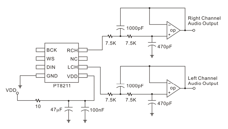
The DAC chip does 8x oversampling with what looks like a CIC interpolation filter. The lowpass on the output in the schematic above gets rid of the residual noise. By my calculation that's a 2nd order lowpass with a 30.95kHz cutoff.
Unfortunately we don't want unity gain, we want something like a gain of 5, and an adjustment to control the output level. The compromise circuit I came up with was this:
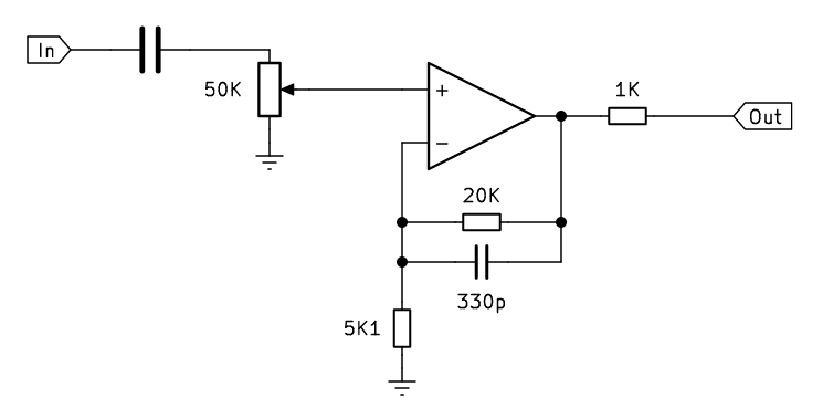
As a first order filter this should give a cutoff frequency of about 24kHz. The gain is fixed at about 4 with a stereo potentiometer to attenuate the signal before the gain stage. This is the best way of doing it, as it lets us use a logarithmic (audio taper) potentiometer. Trying to adjust the gain would both affect the filter and most likely require an anti-log taper. Anyway, the part values were chosen just on what I could find, and it didn't need to be perfect.
The idea was to double this up for stereo output, but there was no way I'd have time to finish that. The two mono output jacks were ambitious, only one of them got wired up.
That's a TL072 and the board stuck onto it is a very cheap boost converter giving +/- 15V supply from the 5V input. This was all very poorly thought out, but I wasn't sure how the synth would ultimately be powered and this at least let me test it easily. The boost converter definitely injects some unwanted noise, that can be heard when the output is low.
If we did implement stereo, we'd still want it to drop to mono when only one cable is connected. It would be possible, but tedious, to detect in software and change the output accordingly. But since we've got that 1K on the output, it would probably be fine to have a switched jack that just shorts the outputs together if only one cable's connected. The two 1K resistors would merge the signal in hardware.
Another improvement would be to add an AC/DC coupling switch. The big capacitor on the DAC output removes the DC offset, but it also limits what we can do at the lowest frequencies. If we did want to use the synth as a sequencer by setting the pitch input super low, the capacitors would make the output somewhat useless (kind of the opposite of portamento). A simple switch could let us flick them in and out of the circuit.
The Event
The synth I took with me was half-finished, but I figured as long as most of the soldering was done I could finish off the software while I was there. I just about managed to get something viable together. The sides did not stay attached.
Here a medical professional draws an ECG waveform. P-Q-R-S-T!
Post party
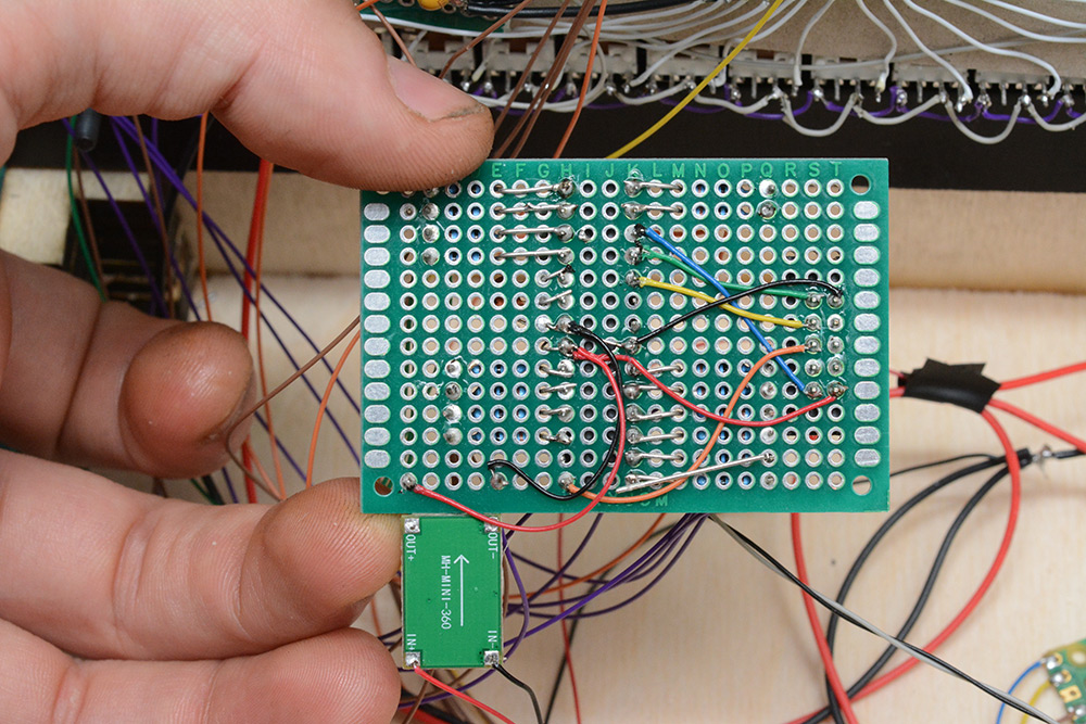
When I got back, I put the final touches on the software. I also really wanted to fix the LED circuit. The first six LEDs were noticeably dimmer due to the ATmega port behaviour. Turning the voltage down caused those port-C LEDs to turn off entirely, and turning it up risked overcurrenting all of them, and also worsened the power supply noise. 16 LEDs at 20mA each is 320mA, that doesn't sound like much but there's a lot of long thin wires in the construction.I added extra current limiting resistors, so we could up the voltage. I removed the buck regulator and wired the board to the 5V supply, with a little LC filter.
The gray wire in the top right is the serial data. I originally had this paired with a ground wire for signal integrity. In the shot above, I've removed the ground wire that led to the pico, and tucked it to the side. My thinking is that it was forming another return path for the LED current, leading to ground differences on the different boards. The serial data seemed to be decoded fine without it, so best to minimise stray currents.
Ultimately I added bigger wires to power the LED board, and eventually just increased the hysteresis on the coarse pitch knob to stop it wobbling. As mentioned in the video, the right way to solve this problem would be to use an opamp to sum the pitch sources in analog before they get to the 16-bit ADC.
Another thing I experimented with was a better power supply. The 5V lead was being fed from a somewhat noisy supply, and there was certainly some voltage drop. I tried out fitting a big 78L05 linear regulator, and supplying the synth with 9V or 12V.
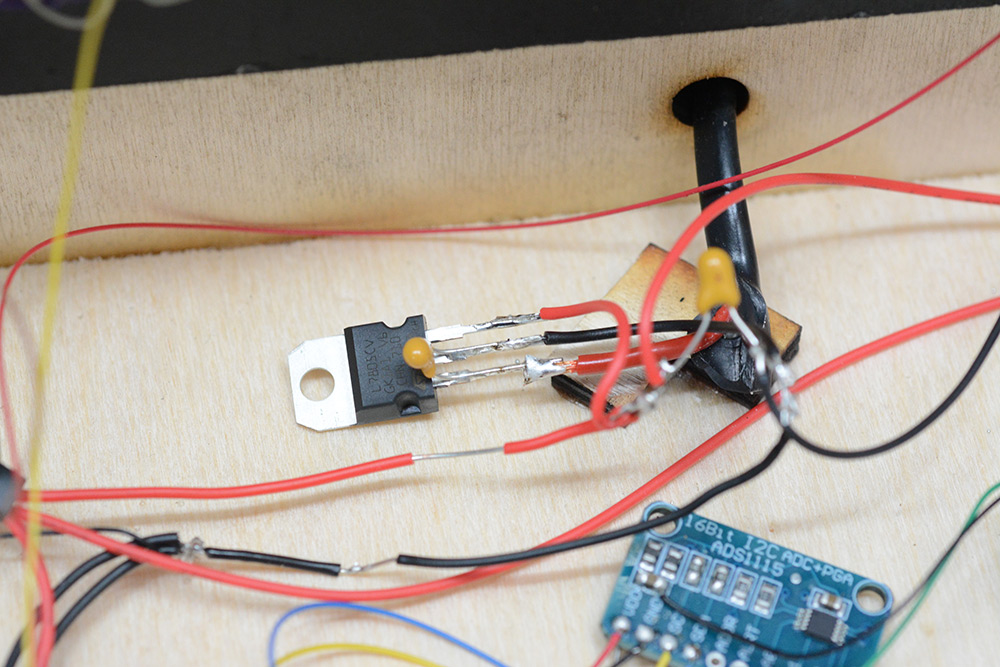
This made virtually no difference, except now we had a nice source of heat within the box. Next I replaced it with a switched mode step-down module.
And yet still there were power supply problems, particularly with the pico. Its 12-bit analog measurement was showing about 60-70 units of noise. It seemed to get worse when I closed the box, so I then moved all the switched-mode supplies outside of the box to see if that helped. It didn't really. As mentioned above, I disabled the Pico's onboard 3.3V regulator and fed it from the linear, without much perceptible change.
There are several other, rather boring, attempts I made at fixing the supply noise, but after a couple of hours I moved on. I think the best thing to fix the noise issues would be to just re-wire all that mess to be cleanly arranged, without wires crossing over each other.
The last step was fixing the side panels in place. I made cut-outs on each of them so that opening the lid would be easier, and also to potentially allow a USB cable access to one of the chips while the box is closed if we need it. The side panels were spray painted and then screwed in place, rather than glue. The screws were countersunk.
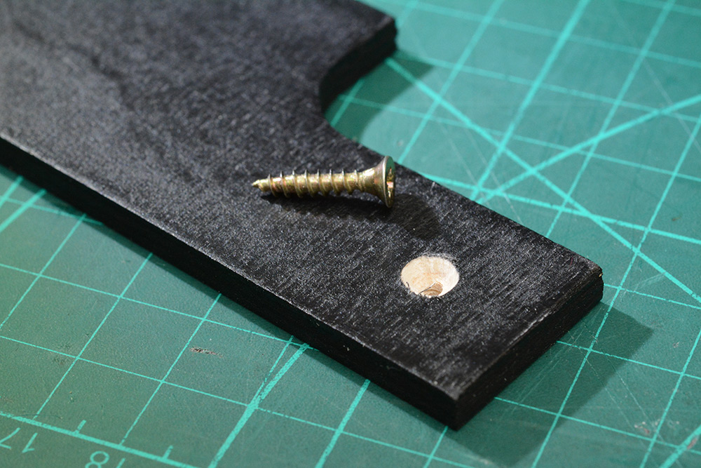
After that picture I darkened the countersink with a sharpie.
Conclusion
It was a mad rush, but I just about managed to meet my goal.
Todo:
- Finish stereo
- Finish the labels, laser etch some nice panel design
- Illuminate partial sliders
- Turn it into a eurorack module and earn cash money
We could trivially turn this into a MIDI controller. Either by augmenting the Pico firmware or adding another microcontroller to listen in on that serial data. I'm not sure there's much need to do that though.
There is a temptation to add a MIDI input, skipping the CV stuff, but that's not really in the spirit of this project.
It would be nice to have some built-in envelopes and LFOs though.
I'm also now tempted to build a new software synthesizer, closer in design to this super-simplified interface.
At some point in the future, I will publish the source code for the microcontrollers in this project. If you think the wiring's a mess, well, the less said about the source code the better. In the mean time, if you missed it, I published the source code for the flash synth a while back.