
Touch Screen as a MIDI Ribbon Controller
28 Jun 2016Progress: Complete
You can pay hundreds of pounds for a MIDI ribbon controller. Even the cheapest ones are way more than they should be, I mean, much like a theremin, most users are only going to want it to do swooping funky sounds. But unlike a theremin, there's no technical difficulty in producing a linearly-responding instrument.
I only found out about the Korg Monotron after searching for standalone ribbon controllers, and astoundingly it was actually the cheapest option. I went to the trouble of writing some pitch-detection software so I could plug it into my computer's line-in port, and use it to control my synths. Functional, but a hassle.
You can buy the component that makes up the Monotron's ribbon on its own, but it costs about £10. For a glorified resistor, this is ridiculous.
You can build your own ribbon controllers, from magnetic tape, or carbon paper, or a bunch of other ways, but these all seem to me like they're going to break very quickly. One of the difficult bits is keeping a nice amount of separation between the two resistive layers. Resistive touch screens do this using micro glass beads which give a very even separation.
This got me thinking, and then that got me looking. Yes, you can get a resistive touch screen for 99p including postage.
So when it arrived there were actually a couple of problems, first that it's built on a layer of actual glass, and second that the connector is miniscule. Very difficult to solder to – but not impossible.
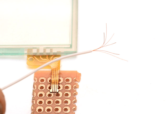
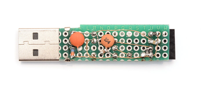
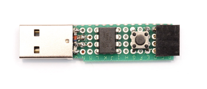
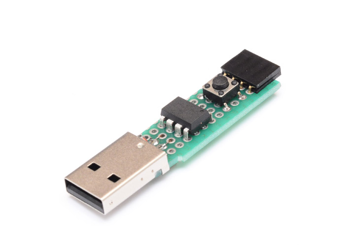
It's much easier if you have a solid surface to work on, so I superglued the connector onto a bit of perfboard. I found the thinnest multicore wire I had, and unravelled it to pick off individual strands.
Then I applied the leet skillz0rs.
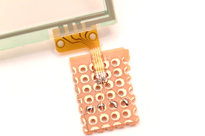
Functional. The screen is only about two inches across though, so I'd ordered a bigger one too. The bigger one is seven inches, and its connector was much easier to solder to.
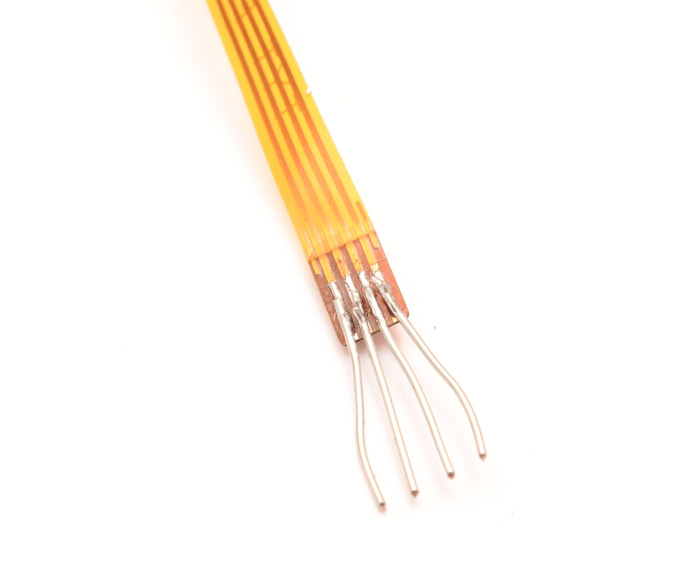
1mm pitch as opposed to 0.4mm pitch.
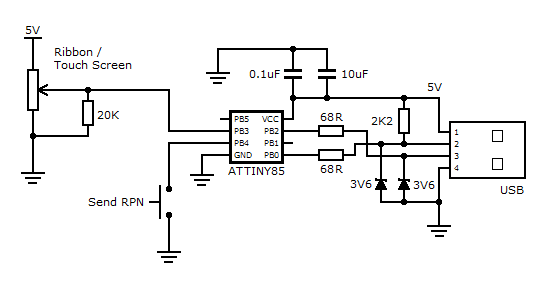
So – some theory. 4-wire resistive touch screens are made from two layers of resistive material. When you touch, they're pressed together at that point and make contact. One layer has rails on each side, the other has rails top and bottom. If you apply a gradient to these rails (for instance by sticking one to ground and the other to 5V) then the other rails will read out an analog voltage corresponding to one coordinate of the touch. You're supposed to switch between measuring X and Y coordinates quickly to get your two-dimensional result, but for one dimension we can permanently wire up a gradient on one sheet, and read the analog voltage off the other.
We could actively detect whether there is or isn't a touch, but to keep it simple I stuck a pulldown resistor (~20K) to ground so that a voltage of zero would mean no touch. Then I cracked out the old V-USB MIDI setup.
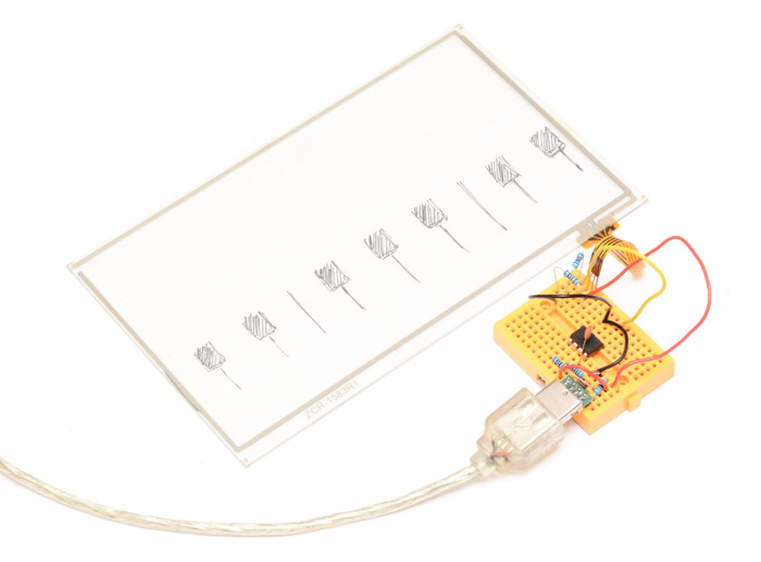
The ATtiny85 makes an analog reading and turns this into pitch bend messages and suitably placed noteon/noteoff messages. The keyboard is just drawn on a piece of paper underneath as a guide.
Most synths have the default pitchbend range of +/-2 semitones, but this can be expanded using the RPN messages. You need to send:
- Continuous Controller 101 with value zero; then
- Continuous Controller 100 with value zero; then
- Continuous Controller 6 with value equal to +/- number of semitones pitch bend range.
Since this is tough to remember (or just inconvenient) I added a button you can press to send this. (Actually I originally had it send it when it powered up, but it was quite easy for most synths to miss this.)
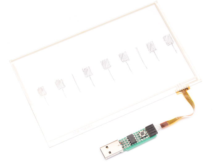
The touch screen connects to a header connector, so I can stick either of these two into it. And the way the pins are laid out, if you flip it over before inserting, it will change from horizontal to vertical behaviour.
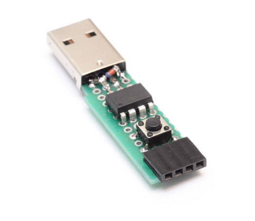
As usual I left enough room around the chip to be able to reprogram it using a test clip.
So my hope when I bought these screens was that I could cut them into strips, and have ten ribbon controllers for the price of one touch screen.
It's unlikely to happen, however, since the glass backing is one of the resistive layers. I tried peeling one apart, and it's just one plastic film on top of glass. The other layer must be some kind of coating that can't be peeled off.
I've not tried it, but I imagine if you pulled off the plastic layer and cut it up, then placed those strips against themselves, it might work as a ribbon. I don't know about the separation though, whether the glass beads are stuck to one side or something. Worth experimenting with.
Another idea is just to cut the glass and plastic together, creating a smaller glass-backed ribbon.
It's a shame that we're just short of one i/o pin, but if we switched to a bigger chip we could quite easily extend this to read both axes of the screen and send 2D controller data.
Well, there you go, a functioning USB-MIDI ribbon controller for less than a fiver.
Approximate circuit (add capacitors to taste):
Here's the relevant bit of the source code. (I'm getting tired of repeating all the V-USB code here. If you follow objective development's MIDI example, then replace the main bit of code with the following, it should work nicely.) Alternatively grab the hex file and remember to set lfuse to C1.
/* ------------------------------------------------------------------------- */
/* --------------------------------- main ---------------------------------- */
/* ------------------------------------------------------------------------- */

void sendPitchBendRange(){
  uchar pitchBendRange[8] = {0x0B, 0xB0, 101, 0, 0x0B, 0xB0, 100, 0};
  while (!usbInterruptIsReady()){
    wdt_reset();
    usbPoll();
  }
  usbSetInterrupt(pitchBendRange, 8);

  while (!usbInterruptIsReady()){
    wdt_reset();
    usbPoll();
  }
  pitchBendRange[2]=6;
  pitchBendRange[3]=8; //Number of +/- semitones
  usbSetInterrupt(pitchBendRange, 4);
}


int main(void) {
  uchar  i;
  uchar  sentPBR =0;
  uchar  calibrationValue;
  uchar  midiMsg[8];
  uint16_t  val=0;
  uint16_t  lastVal=0;

  DDRB = 1<<1;
  PORTB |= 1<<4;
  OCR1A = 1;
  TCCR1=0;
  OCR1C=50;


  calibrationValue = eeprom_read_byte(0); /* calibration value from last time */
  if(calibrationValue != 0xff){
    OSCCAL = calibrationValue;
  }
  usbDeviceDisconnect();
  for(i=0;i<20;i++){  /* 300 ms disconnect */
    _delay_ms(15);
  }
  usbDeviceConnect();

  wdt_enable(WDTO_1S);

  usbInit();
  sei();

  for(;;){  /* main event loop */

    if ((PINB & 1<<PB4)==0 && !sentPBR) {
      sendPitchBendRange();
      sentPBR=1;
    }

    wdt_reset();
    usbPoll();
    if(usbInterruptIsReady()){
      ADMUX = (1<<MUX1 | 1<<MUX0); //PB3
      ADCSRA = (1<<ADEN|1<<ADSC|1<<ADIF|1<<ADPS2|1<<ADPS1);
      while (!(ADCSRA & (1<<ADIF)));
      val = ADCW;

      if (abs(val-lastVal)>=1){
        i=0;
        if (lastVal==0) {
          midiMsg[i++]= 0x09;
          midiMsg[i++]= 0x90;
          midiMsg[i++]= 0x40;
          midiMsg[i++]= 0x7F;
        }else if (val==0){
          midiMsg[i++]= 0x08;
          midiMsg[i++]= 0x80;
          midiMsg[i++]= 0x40;
          midiMsg[i++]= 0x00;
        }
        if (val!=0) {
          midiMsg[i++]= 0x0E;
          midiMsg[i++]= 0xE0;
          midiMsg[i++]= val&0x7F;
          midiMsg[i++]= val>>3;
        }
        lastVal=val;

        usbSetInterrupt(midiMsg, i);
        sentPBR=0;
      }
    }

  }
  return 0;
}