
RC Transmitter as USB Joypad
14 Oct 2016Progress: Complete
Rambling Preamble
Feel free to skip ahead to the interesting stuff.When I was very little, I remember looking out of a car window as we drove somewhere and seeing, in the distance, a tiny little aeroplane. Minute. And underneath there was a man holding a controller. As you might imagine, my jaw dropped as I realized there were model planes that really fly. None of that elastic band, polystyrene glider nonsense. Remote control! The first thing I asked, though, was: is there such a thing as a remote control helicopter?
Perhaps I was in a helicopter phase. I dunno, there's just always been something about helicopters that's so cool. So I soon found out that Yes, RC helicopters existed and No, we could not afford one. There were also many people who told me that they are extremely hard to fly (as if that somehow would put me off...?). But persistence is a strange thing and I said I would save up. I remember going to open a bank account, for the very first time, and from then on all of my pocket money, all of my christmas and birthday gifts, all of it went into the Helicopter Account.
It took a few years, which when you're tiny feels like forever. I suppose it was about 30% of my life up to that point. Finally I hit £500. Surely, surely this would be enough for one? I researched it (which in those days meant reading RC model magazines) and found that yes, I could afford a small electric model. There were excellent reviews of it. I took the plunge! Except, when I went to buy it, innocent little me was a little too easily swayed, and the man in the model shop said, "you could buy that one, yes, or, you could buy this new one that's just arrived, and it's cheaper!"
So I'll never know how good that original one would have been, but the one I got, 'twas a disappointment. I suppose there are a number of reasons why:
- It was too small to fly outside. It had a gyro for yaw control, but the main stability was from a flybar. Even the tiniest gust of wind was impossible for a beginner to outlive. But it was too big to fly inside! Unless you had a great hallway or something, regular indoor flight was extremely crashy.
- The main rotor blades were brittle, and a single crash normally meant fitting a fresh pair. This was more of a problem than it should have been, because everyone who saw the helicopter had to have a go. I would refuse, of course, but the moment I left the room I'd hear it spin up and then SMASH. The crashes were even more dramatic with the splintering of the blades. There was so much momentum in that rotor, and the tips were razor sharp at those speeds – multiple people got cut. Blood everywhere. Having the right environment to fly in also apparently meant keeping it a secret from everybody.
- The batteries were terrible. They were NiCads I think, took forever to charge and lasted no time at all.
There were probably other reasons too, but I never learnt to fly it well. In fact the best I ever did was hover for a bit (but that is, of course, a lot harder than it sounds). What an anticlimax the whole thing was. I left the world of RC helicopters.
I did experience a bit of the other remote-control fields: RC cars, of course, became very cheap at some point and they were reasonably entertaining, but just toys. They either took a phenomenal amount of disposable batteries, or were the type that recharged from the controller. Both were terrible. And the RC signals were sent over 40Mhz, AM or whatever, always interfering if you tried to race someone else. Next there came the infra-red control coaxial helicopters, and they were just impossible to fly. No, they could be flown, but they were impossible to fly in the direction you wanted them to fly in. Also, without a swashplate, it just seems so pants.
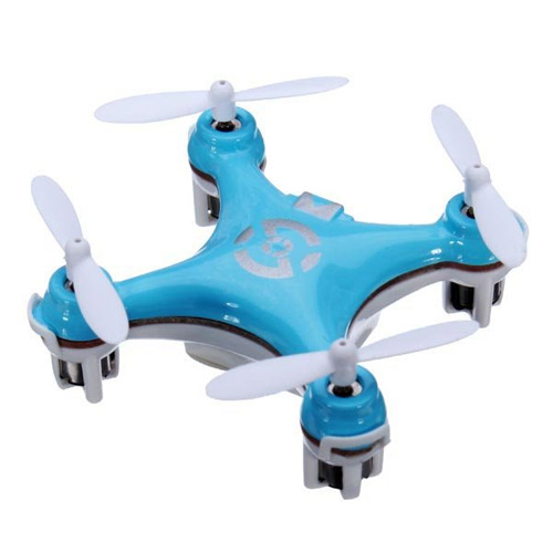
Years passed. Now, I am no longer a kid. But a while ago I got a gift, this thing, it's called a Cheerson CX-10 and it is a nano-quadcopter. I didn't have that great expectations for it but OH BOY I WAS WRONG.
Of course it's been years. Of course the technology has improved. But I was not prepared for the quantum leap forwards this generation of quadcopters represents:
- MEMS gyros, developed for smartphones of course, combined with better processing power, means the whole thing is insanely stable. The auto-levelling of these easy-to-fly quadcopters means even a total beginner can hover without a problem. The learning curve is easy, too, and you can choose the dynamic range of the sticks.
- It's small enough to fly indoors, even in a small bedroom, and chairs and tables become three-dimensional assault courses for you to weave through.
- 2.4Ghz communication with pairing – what a godsend. You can fly a whole bunch of these things in the same room without interference.
- It charges from USB. Kiss disposable batteries goodbye! (Well, the controller takes AAAs, but in the hundreds of flights I've had with this thing I've never had to replace them.)
- LiPo batteries are just the bee's knees.
- Perhaps the best thing of all: the entire quadcopter, with controller, ready to fly, costs £10. That's 45 times cheaper than the last helicopter I bought. That's cheaper than the replacement rotor blades of the last helicopter I bought. The bloody thing's basically disposable! But despite that, it is in fact possible to buy replacement parts for it. Magnificent!
Where was this thing when I was young? Oh well. Now that I'm a grown up I've decided to waste away the rest of my life buying all the toys I missed out on. I bought a whole bunch of different nano-quadcopters and got quite good with them. I can now fly a CX-10 through the carrying handle on my folding chair (that's about 4 inches by 1.5 inches). I also really enjoyed one called the Eachine H8 3D, which can fly upside-down, something I felt was missing from the CX-10, along with the lack of interchangeable batteries. Those were my two minor complaints about it: having to wait for it to recharge, and having to get up and right it by hand when it lands upside-down. The H8 3D solves both of them.
There are some incredibly talented people over at RCgroups.com who have modified and reverse engineered these things too. The modifications include the obvious ones (First person view, of course) and things like building generic controllers, which can use multiple protocols and control different models. For someone who's been out of the game for years, this whole thing can seem a bit overwhelming. The processor in the Eachine H8 is an STM32F-something, which is a generic embedded microcontroller with an ARM-cortex core. So, some talented (or perhaps just really persistent) people have written alternative firmware for the quads, which implements new features, better control, and acro mode (no auto-self-levelling).
I recommended these quads to so many people, that after a while (more for a joke than anything) I set up a referral link so I can get 4% of the sales. Haha! 40p for me! I suppose linking to it now would make the whole text above seem fake and driven by my lust for money, so I'll omit it for honesty's sake.
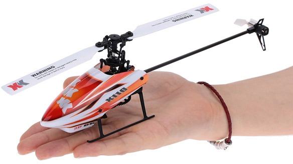
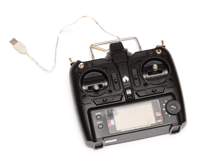
Finally, about two weeks ago I was reminded for some reason of my earlier helicopter antics, and I wondered. Technology has improved. Nano quads are insane. I wonder where RC helicopters are now? After a few days of pondering and searching and pondering some more, I bought myself one. I settled on an XK K110 micro collective pitch helicopter, which cost just under £100. Sheesh, that's ten CX-10s... but still a fraction of what my old helicopter cost.
Is it any good? Who knows? it's only just arrived. But this time I have the internet to help me learn to fly it. And the general consensus is: use a simulator. So I downloaded a demo RC helicopter simulator (it's called Heli-X) and tried it with a usb joypad and whoa! It's almost impossible to control unless you set the curves to their extremes. Evidently we need to use a real transmitter to control the simulator, and yes, at last we have reached today's project. I apologise for the over-use of emphasis in the preceding paragraphs.
PPM to USB
In the manual for the K110, which incidentally is written in abysmal english, I noticed a label for a PPM jack.
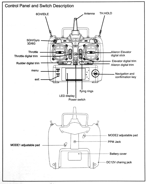
Interesting! This means we can potentially build a cable to connect to USB without modifying the controller in any way. The DC12V socket on the diagram is not present on the real controller, but the PPM jack is. The socket turned out to be a mono 3.5mm audio jack, and scoping it showed a familiar trace:
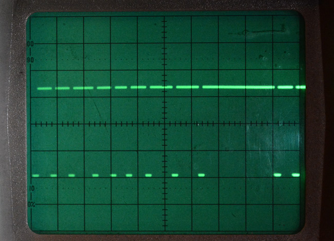
There's PWM (pulse width modulation) and PDM (pulse density modulation) and probably others but what we have above is PPM (pulse position modulation). The fact it idles high means it's the futaba inverted style PPM. But why am I explaining PPM?, when you could be watching Rex Garrod explain it in this excellent clip from The Secret Life of Machines, in which he demonstrates the operation of BRUM. (That's not an acronym. That's me shouting. It's a kids' TV show, so I'm back into overemphasis mode.)
A precursory search showed lots of people making joypad-to-PPM converters, which is the opposite of what we want. There were also a few PPM-to-USB-joypad projects, even AVR-based ones. I figured I could best them by building the converter cable entirely within the USB jack, in other words, identical hardware to the USB Red Button. So, I set off to implement a USB joypad on an ATtiny85.
Report descriptors
The HID report descriptors tell the host what the USB device is going to send (or receive). These have a notoriously dense format and bizarre conventions which mean that up until now I've just copied them from other projects or existing devices. I thought I'd have a go at usb.org's HID descriptor tool (Dt.exe).The PPM has eight pulses, the last two send a constant value. The first four are the throttle, then roll, cyclic pitch, yaw, and then collective pitch. The other pulse is wired to a switch, which seems intended for landing gear on a plane, but here it's used to switch the "6G" auto-levelling on so that it flies like a quad. Pussy-mode, in other words. Usually the collective pitch stick works both throttle and the upper half of the collective range, but if you hit idle-up, it puts the throttle to a fixed amount and the collective pitch becomes symmetric (so you can fly upside down). In addition, there's a dynamic range switch, which goes between two presets. And to top it off, these presets can have their curves adjusted in the menu on the LCD screen.
It would be far more convenient if these curves were not applied to the PPM output, but we can work around it. I guess we need five axes, and one button. This is a very awkward thing to encode in the descriptor format, so to begin with I just went with four axes and no buttons. Windows acknowledged this, but it was behaving strangely. Dt.exe offers descriptions like Throttle and Yaw, but every single joypad that is actually sold seems to list the first four axes somewhat arbitrarily as X, Y, Z, and Rx. I became worried that it would not work cross-platform, and eventually chickened out and went with an example report descriptor from the internet.
Here's the descriptor I ended up using, which is just 8 axes. We may as well send the value for each of the 8 pulses.
const PROGMEM char usbHidReportDescriptor[USB_CFG_HID_REPORT_DESCRIPTOR_LENGTH] =
{
	0x05, 0x01,                    // USAGE_PAGE (Generic Desktop)
	0x15, 0x00,                    // LOGICAL_MINIMUM (0)
	0x26, 0xff, 0x00,              // LOGICAL_MAXIMUM (255)
	0x75, 0x08,                    // REPORT_SIZE (8)
	0x09, 0x04,                    // USAGE (Joystick)
	0xa1, 0x01,                    // COLLECTION (Application)
	0x09, 0x01,                    //   USAGE (Pointer)
	0xa1, 0x00,                    //   COLLECTION (Physical)
	0x09, 0x30,                    //     USAGE (X)
	0x09, 0x31,                    //     USAGE (Y)
	0x95, 0x02,                    //     REPORT_COUNT (2)
	0x81, 0x82,                    //     INPUT (Data,Var,Abs,Vol)
	0xc0,                          //   END_COLLECTION
	0xa1, 0x00,                    //   COLLECTION (Physical)
	0x09, 0x32,                    //     USAGE (Z)
	0x09, 0x33,                    //     USAGE (Rx)
	0x95, 0x02,                    //     REPORT_COUNT (2)
	0x81, 0x82,                    //     INPUT (Data,Var,Abs,Vol)
	0xc0,                          //   END_COLLECTION
	0x09, 0x34,                    //   USAGE (Ry)
	0x09, 0x35,                    //   USAGE (Rz)
	0x09, 0x36,                    //   USAGE (Slider)
	0x09, 0x37,                    //   USAGE (Dial)
	0x95, 0x04,                    //   REPORT_COUNT (4)
	0x81, 0x82,                    //   INPUT (Data,Var,Abs,Vol)
	0xc0                           // END_COLLECTION
};
The length is 50 which needs to be set in usbconfig.h. Ry, Rz, Slider and Dial are again the conventional axes to use. If there's any logic to this, it may be to do with the numbers going from 0x30 to 0x37 in sequence.
Timing the PPM
The time between the pulses is what we want to measure. This would conventionally be from rising-edge to rising-edge, but here the signal is inverted. The range of times is between 1 and 2 milliseconds, and the entire frame of 8 pulses is repeated every 18ms. Immediately a problem becomes evident: the ATtiny85 only has 8-bit timers. If we could prescale one of these to be exactly the right timing, we might be able to measure it and send the value unscaled. Given that we're already using OSCCAL to tune the internal oscillator to match the USB speed, this is pretty much impossible to do.However, there's a way of making a higher resolution timer on the tiny85 by combining it with the USI timer. It's possible to configure the USI timer to be clocked by the compare-match of timer0, which gives us effectively a 12-bit timer. We set the compare-match value of timer0 to 255 and this should serve us nicely. But! Timer1 is the timer with the 14-bit prescaler, and timer0 only has some very limited values to choose from. We're running at 16.5Mhz, and 12 bits gives 4096 values, and we want the timer to last for over 2ms. So... a prescaler of 8 would last 1.9859ms, or the next prescaler of 64 would last 15.8875ms. Inconvenient! Using 64 gives us worse resolution than just the 8-bit timer with the 14-bit prescaler, and using 8 is not long enough to last to the next pulse.
I thought I'd try the prescaler of 8, just to see... and indeed, the pulses can be a little over 2ms apart. I set it to toggle a pin on the overflow of the timer, and scoped it next to the PPM to confirm. However. The pulses were all uniformly 300μs wide, so, if we start counting from the rising edge, that is, the end of the pulse, until the falling edge (start) of the next one, and add 0.3ms, we might just get away with it.
As it turned out, this functioned. But the timings were all over the place, it definitely needed to be scaled. Since we're programming in C, that should be easy, right? I wrote a little system to measure the minimum and maximum timings for each pulse, then scale the result using (shock horror) floating point operations. You have to really push to get the compiler to do this on an 8-bit architecture.
v = ((USISR&0x0F)<<8) + TCNT0;

reportBuffer[pulse] = (uchar) ( ((uint32_t)(v-vmin[pulse])<<8) / (uint32_t)(vmax[pulse]-vmin[pulse]) );
Luckily the processor is actually idle for most of the time, since the timing is done by hardware and the USB interrupts only take up a small fraction. v, vmin and vmax are of type uint16_t. The min/max scaling would place the value between 0 and 1, so the pre-shifting by eight means the final result is between 0 and 255.
After all that, we had some nicely scaled PPM readings coming through on the windows gamepad testing page. And you know what, it was totally unsatisfactory.
Jitter! And I tried for quite some time to get rid of it. My conclusion was that the USB interrupts were throwing off the timings. (Note that the gif above is illustrative only, I just grabbed a few screenshots, the real jitter is not as obviously looping as that.) By scoping the USB data line and the PPM at the same time, it's possible to see the USB talk start up just as a pulse is finishing, which delays the reading of the timer. This is quite confusing in that there were multiple AVR PPM USB projects on the internet which did not mention this. Since USB is host driven, we can't – as far as I'm aware – do anything but respond to the requests as they come in. I don't think we can change their timing. And we can't change the PPM timing either since the transmitter is driving that.
I had, rather arrogantly, boasted to a friend that I would have the controller finished by the following morning. So, even though most of the day was gone, I was not prepared to accept defeat.
Alternatives
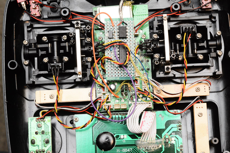
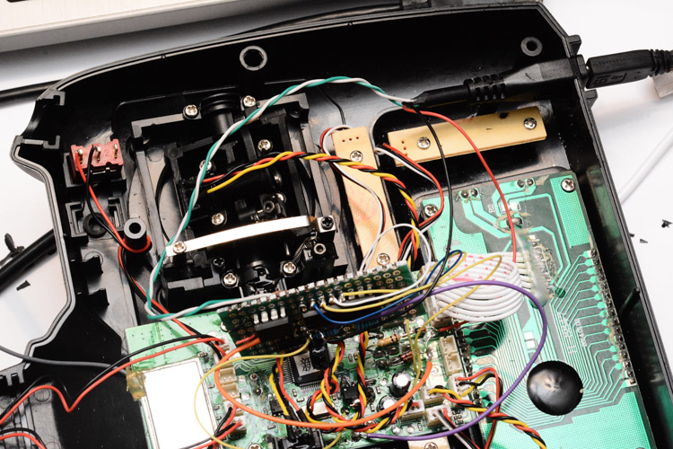
So, I have an nRF24L01+ module, perhaps we could directly read the 2.4GHz being transmitted and send that as USB reports? I think the communication is bi-directional, which isn't fatal for the project, and I wouldn't be surprised if the protocol has already been reverse-engineered by the people of rcgroups.com. But, the transmitter runs on AA batteries and I had already planned to power it over USB when connected. For this reason I also ruled out using a reflashed HC-05 module as a Bluetooth gamepad.I opened up the transmitter to take a look.
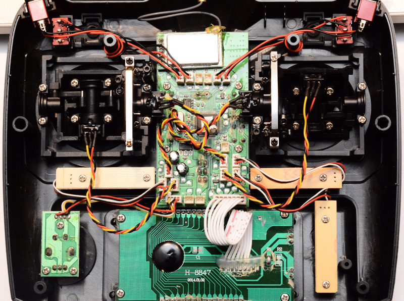
Interestingly, there are holes for more switches in the case which have been plugged with rubber caps. And on the board, there are unpopulated connectors. I tried shorting one of these connectors, and yep, one of the last two PPM pulses shifted. It's secretly an 8-channel transmitter.
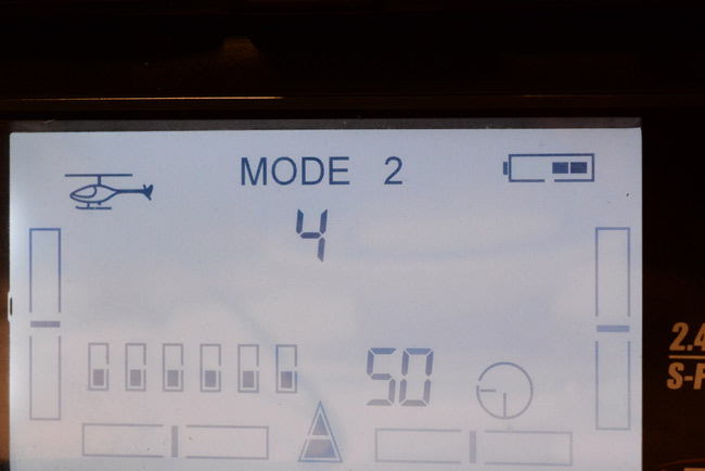
The mechanics are quite interesting too. You can convert the controller over from Mode 2 without dismantling it, just poking a screwdriver through the four holes in the back. The spring tension on the throttle stick can be re-applied and the metal brake is loosened, then the opposite is done to the other stick, and you've switched modes. I'm also surprised to see so many circuit boards in one device, usually manufacturers try and stick to a minimum. Here we've got six boards in four different processes. There's also the wireless module at the top, which is on a separate board as well, with its own bit of shielding.
I scoped the signals to it, and while I could see the movement of the sticks affecting the binary data, it was being sent over SPI at somewhere near 500kHz (I didn't actually measure it) and it was immediately evident we couldn't read this while still doing the bit-banged USB. I also found a trace which turned out to be the display line, I could see the sticks affecting it, but in a weird bit-shifting way, and it turned out to be the little bar-graph on the LCD for each stick.
Direct Analog Readings
After scoping around a bit more, it was obvious that the best thing to do is to read the analog inputs directly. Each axis is a potentiometer between the 3.3V and ground, which plugs into a JST connector on the board. Conveniently, there are test pads next to each connector that we can solder to. We need to be careful not to muck up the on-board circuit's reading of them, but with high-impedance inputs on a microcontroller this shouldn't be an issue. This method also has the advantage that the software is dead simple to implement, especially as we've already got the USB gamepad part running.Except... it isn't dead simple, is it. After USB, the ATtiny85 only has three pins left and only two of those have ADC channels. By this point it was about 11pm. We have two options: use a different chip, but since I didn't have any that could run the USB and had 4 ADC channels to hand, that meant giving up, ordering one, and waiting for delivery; or, do something stupid. I rummaged through my drawers and finally found an analog multiplexing chip (for some reason it had ended up in the box of 74 series chips).
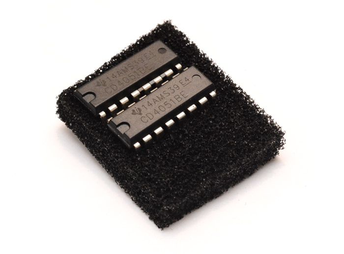
Ah yes, the CD4051B, which multiplexes 8 channels using a 3-bit parallel input.
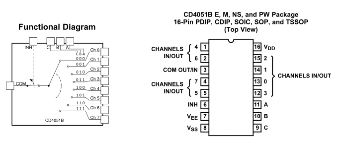
So, we ground one address line and use it as a 2-bit, 4-channel multiplexer and send the reading to our one remaining pin on the micro. Simple. That's it, the project's in the bag now, right?
Power over USB
We want it powered from the USB when connected, and we want it powered from batteries when not, and it can't drain the batteries when it's connected, and the circuit can't draw more power when it's on batteries, and the battery voltage mustn't be dumped into the USB port, and the USB port mustn't try and charge the batteries.The standard way to use multiple power sources is by sticking each one through a diode, then there's no chance of backflow. But the diode drops some voltage, which is inconvenient, or at least, wasteful. The circuit takes 9V from the batteries, and I sure hoped we wouldn't need to add a boost converter (even though I do happen to have a few spare). But looking at the circuit more closely that 9V actually goes straight into a 3.3V linear regulator! What a waste of battery life.
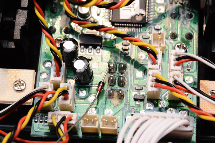
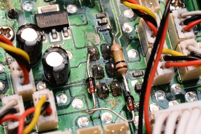
The battery connects to one of the connectors at the bottom. The six through-mount solder blobs in the middle are the on/off switch, and to its 'on' leg I've soldered a diode where the USB power will come in. This means we can leave the switch in the 'off' state and the battery won't be drained, but it can be powered from USB. If it's turned on it will switch to battery power. The fat trace leading northwest of the pin goes to the input of the linear regulator, an AMS1117-3.3, a super common chip which I happen to have a strip of in one of my boxes.
The regulator has a drop of about 1.1v, so with the diode dropping 0.6v we should just be okay from 5V to 3.3V. I applied the 5V, and was greeted with a loud beeping noise, screen going crazy. It's the low-battery alarm, the circuit knows that it's undervolted and is refusing to turn on. The little battery icon on the screen was flashing.
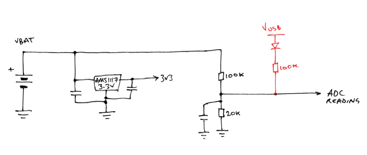
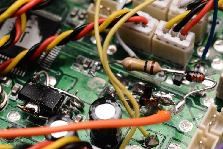
How is it measuring the input voltage? There's actually another trace coming from the switch, this time heading to three surface-mount parts and then onwards to the main processor. The processor is running at 3.3V like the rest of the circuit, so in order to measure the battery voltage, it uses a potential divider to measure a fraction of it that's within the range of its ADC. I soldered a green wire to the point of interest.
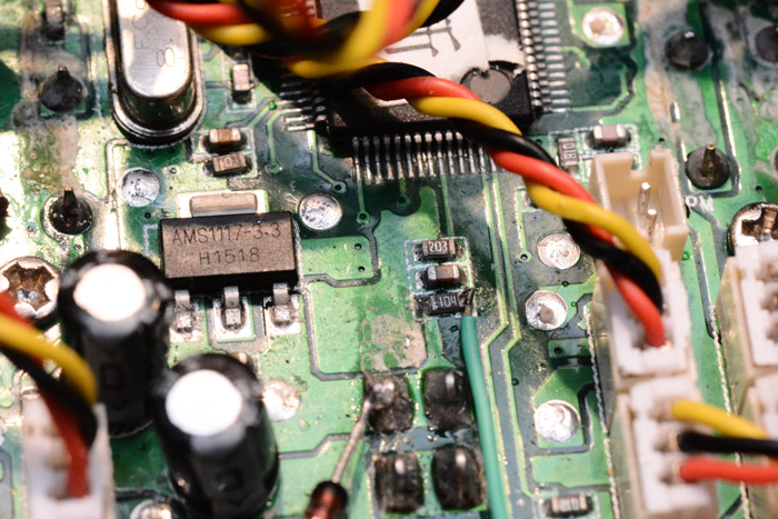
There's a 100K and a 20K, and a cap. If the battery were at 9 volts, this means the processor's pin would see (20/120)*9 = 1.5 volts. So we need a way to pull this up when on USB power. Oh god, resistor calculations, can I remember how to do this? You know what, it just feels like it should be another 100K to the USB supply, with another diode so it doesn't affect the reading when it's genuinely on battery.
To be on the safe side, I first soldered a 500K trimpot to it, and confirmed that as I twisted it, the battery reading went up and down. Excellent. And the halfway battery mark? Spot-on 100K.
I then made this a little more permanent.
My idea was that the protoboard which contains the ATtiny85 and the multiplexer would have its own regulator, powered only from the USB, so it would power down when on batteries. I soldered up the circuit and gave it a shot. And you know what? Jitter, again!!
This time it obviously is an analog problem, so first I added extra ceramic caps to the linear regulator on the main board. This actually improved things, so I poked around some more and noticed the diodes were actually dropping closer to 0.75V. So the linear regulator was in dropout mode and the circuit was only powered at about 3.0V, and its waving about as the current draw changed was mucking things up. If I short out the diode, the readings are rock solid. But then, we lose all that effort of making it switchably USB powered.
I figured I had some Schottky diodes around somewhere, which should have a drop of about 0.4V at these currents, but couldn't for the life of me find them. If you're thinking "well, why not just stick a bunch of diodes in parallel?" I'm afraid that diodes don't work like that. For a start, the exponential voltage / current relationship means that if you halve the current you only change the drop by about 0.06V, and also, as their temperature rises their conductance increases. This means that even if you have loads of them in parallel, unless their forward voltages were exactly identical, all of the current would end up going through just one of them anyway.
I worried about this for some time. I've got mosfets in my drawer, could we use one to switchably connect the correct power source? What about a relay that's only powered up by the presence of the USB voltage? I do have a 5V relay lying around. Sounds stupid, but it could work. Then again, we're using a physical switch to connect the batteries, couldn't we just mechanically change power source? That is a double throw switch, but for some reason they went and wired the battery voltage to the centre terminal. The only way we could do it would be to cut all three traces, and completely rewire the switch. That's also assuming there's nothing on the underside of the board connected to it, which I haven't looked at yet.
Given that I really should have been in bed at this hour, and the controls were rock solid when the diode was shorted out, I decided to leave it like that for now. The USB joypad is at least usable with the simulator, so, primary goal achieved. I ordered some parts ready to finish off later in the week.
But Wait...
I tried the circuit out on battery power again, and I'd ruined it! The power sources switch fine. The controller powers up fine, but there's this mighty beeping. It's the warning that the throttle is not at zero. Usually you want to zero the throttle before connecting to the helicopter, for obvious reasons, so there's a warning beep when you switch the transmitter on. But it wasn't going away this time. And thanks to those handy bar-graph displays of the stick positions, I could see now that none of them had their full ranges of motion anymore, and worse, when you moved one stick it would cause the others to drift. Plug it back into USB power and they're all fine again.The problem, of course, is that bloody analog multiplexer I'm using, which unlike a microcontroller does not tri-state when powered down. The gates all stay half-open and the signal wires from the potentiometers end up mixing together. There is no solution to this other than to power up the multiplexer, even when on battery. How humiliating.
I tied its power rail to the 3.3V of the main board, and still there was a problem: now, just one of the axes was playing up. Clearly it was the one that happened to be connected by the multiplexer over to the ATtiny85. The chip is powered down and I assume the clamping diodes on its input are what are affecting things this time. So, bugger, we have to power up that chip as well, which defeats the point of having separate regulators entirely.
With the chips powered up at all times, and the usb power going straight to the input without diodes, we at least had a functioning USB joypad that had no jitter and could still fly the original 'copter.
The Continuation
The following day I actually managed to find a schottky diode, in a surface mount package (ugh) but I managed to stick legs onto it. When I put it into the circuit, I found that its voltage drop was not low enough anyway. I ordered some new parts including a pack of schottkys and some regulators that are actually worthy of the "low dropout" title. Incidentally, I love how RS components now offer free next-day delivery on everything, even a regulator that costs 50p.The new regulator has a very catchy name: NCV33375ST3.3T3G. It's in the same package as the regulator that's on the board, but guess what, the pinout is different. This means I had to mount it sideways, on bent bits of wire, which isn't at all pretty but hopefully works well. I also left the extra caps that I had soldered on earlier in place. The mess now looked like this:
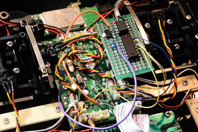
Most of the protoboard junk is on the underside, I wanted the top to be clean so that I could use a test clip to reprogram the ATtiny. The 3.3v regulator on the protoboard is now disconnected. The combination of schottky diode and LDO regulator means we can at last have the power source select automatically without buggering things up, so I shortened the legs to the schottky, it's the tiny black rectangle that's bridging the 1N4148.
It was such a hassle to get to that point that it would have been better to fit a switched-mode power supply. And I would have done, if I'd had any to spare (I have plenty of boost converters, but no buck converters to hand). Fitting a 3.3V buck regulator would actually improve the battery life, so maybe I'll do that at some point.
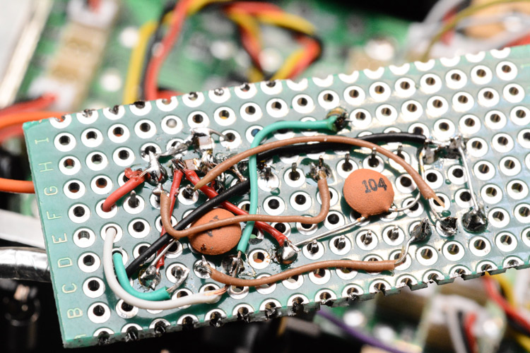
The underside of the protoboard looks like this: (shot taken before disconnecting the regulator)
And the whole thing fits together like so.
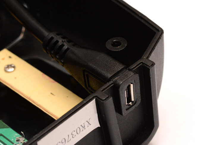
With the circuit "finished" or, at least, functional, the main thing left to do is mount the USB port. Up until now I'd been using a severed USB cable that's soldered to the protoboard, and feeding it out of the gap in the plastic case where the antenna normally mounts.
Looks terribly messy and also the antenna now flops around on a bit of wire (the brass bit is, I think, a waveguide, and the actual antenna is the almost-invisible bit of white wire sticking out of the end). So, simple solution, let's add a panel-mount USB socket.
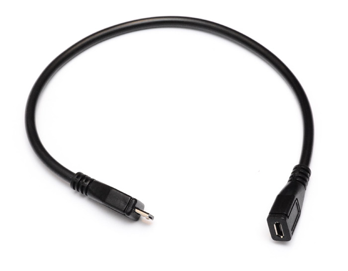
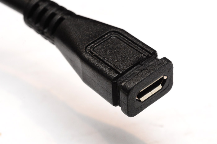
Except... no, nothing about this harebrained project has been simple at all. For some unknown reason, USB panel mount sockets are almost impossible to come by. There are USB-B panel mount sockets, but these are huge and don't seal well to the panel at all, you're just supposed to have a cutout a few mm bigger than the plug, or so it seems. Mini and micro USB are apparently only meant for PCB-mounting. You then, I suppose, butt the PCB up against the edge of the case. But micro-usb ports take a lot of abuse when you're plugging and unplugging them, and even though I had a PCB mount micro-usb socket I couldn't think of a way of securing it that wasn't unacceptably fragile. There are IP67 panel mount USB sockets, which go in a big round grommeted hole, but these are stupidly expensive. So, improvised solution again, I got hold of a micro-usb extension cord, which actually has a female inline connector.
Using a stanley knife I cut a groove all the way around it.
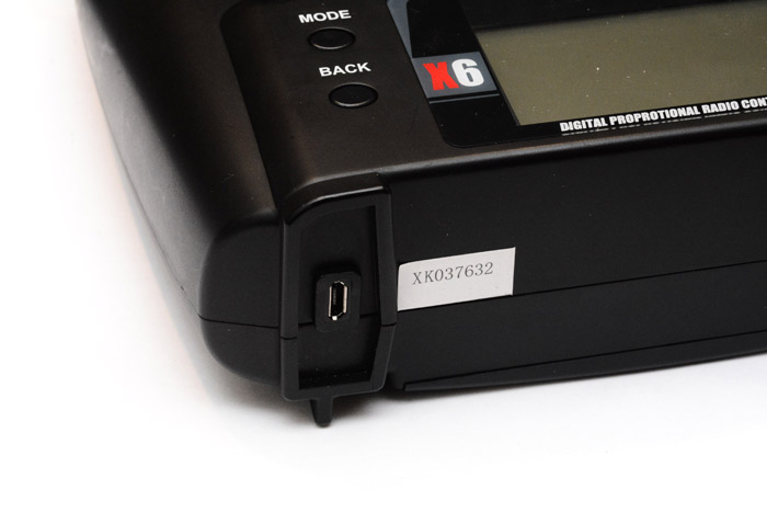
I thought about where the best place to mount the socket on the transmitter was, the top seems logical but actually the surfaces are mostly curved and there isn't as much room when you consider how much the cable will protrude inside. The sides are out of the question, since they're in contact with your palms as you use it. So, bottom is best, and within each foot is a recess which means the protruding socket won't affect the controller's ability to stand up on a table. I cut a U-shaped slot into one of the feet so that the cable can now be jammed in place.
One last look inside and a test-run of the new socket. You'll notice that despite the thickness of this USB extension cable, it was not shielded, which is really disappointing. I twisted the differential data pair together by hand. Also there are yet more capacitors added to the circuit.
Finally we can close the case, with the antenna in its proper place. I think this socket is about as professional-looking as we could have possibly hoped for, and I feel confident that the method is strong enough to withstand some violent USB insertions.
To do
- Send the ATtiny85 to sleep to save power when running on batteries. Could even detect this in analog, since the reset pin can be used for small-range analog readings without disabling it. Just some arrangement of resistors to detect what the voltage on the USB line is. Or, simply wait for a while and if USB hasn't connected, go to sleep.
- Add a buck regulator to improve battery life.
- Start over using a sensible choice of microcontroller.
How is the XK K110? It's actually excellent. Marvellous fun to fly. And whatever they built these rotor blades out of, it's almost indestructible. I haven't yet gotten the hang of flying upside down, but for that, I shall practice on the simulator, using our newly USB-enabled controller. Sublime.