
Quick Release Handlebar Stem
31 Oct 2020Progress: Work-in-progress
The desire for quick-release handlebars has burned inside me for more than a decade.
I specifically mean the stem – a quick release stem clamp would allow the handlebars to fold flat on the bike. The handlebars are the widest bit of a normal bicycle by far, so folding them flat easily halves the space needed for storage. I sometimes do this when transporting the bike, but it means undoing the bolts on the stem with an allen key, which is a hassle.
I am not the only person to have this idea. It's been turned into a product on multiple occasions, but none of them seem to have been successful. Of all the results I found, none were actually available for sale. Here's just sample:
Zenstem
Nice design. Kickstarter in 2016 failed to reach funding goal.
By Schulz Stem Twist
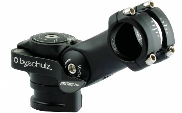
Totally unavailable at the time of writing, although it seems the company hasn't, aha, folded. But the stem is super expensive for what it is (€120) and doesn't pivot in the best way.
Quicktwist stem
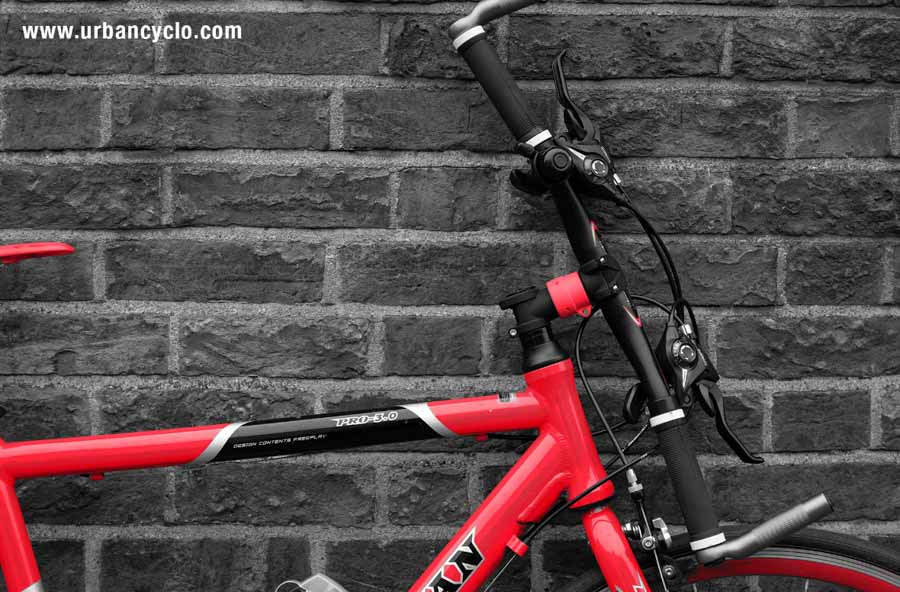
Very startup-y website, not actually for sale yet. 3D printed models, eek!
THINstem
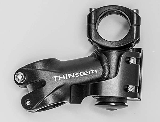
Slightly weirder design, but on the plus side still in business. The out-of-stock message blames the pandemic, which is fair enough.
There were more, but you get the idea. Clearly people want it. But not enough people want it for it to be viable.
But perhaps all it takes to acquire a quick-release stem is a couple of hours of welding?
Construction
Only a complete nutter would try and DIY something like this. For some reason I have no self-preservation instinct (an affliction that often correlates with amateur welders) but please, don't try this at home.
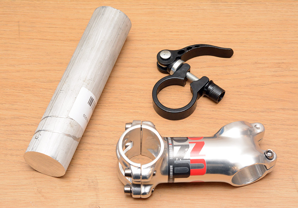
We begin with three important things.
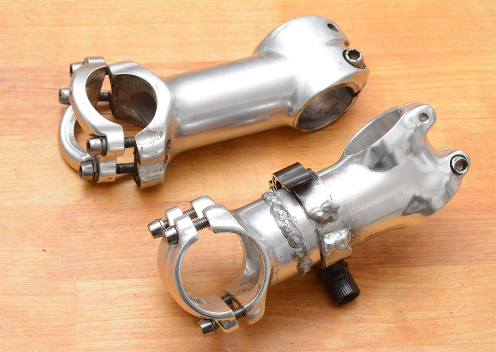
- An off the shelf, brand new stem. I may be dumb, but I'm not dumb enough to saw through my bike stem without a spare handy if it all goes tits up.
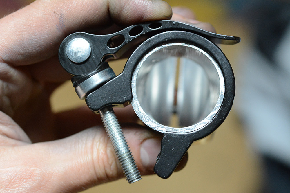
- An off the shelf quick-release clamp. These are super common, this one's intended to replace the seatpost clamp, which is pretty close to the diameter we need.
- A round bar of aluminium stock. This is specifically 6061, partly because it's a good strong alloy, but also because that's what the other two bits are made of and we want to weld to them.
The new stem's angle and length don't quite match the original on my bike. I think I'll weld to the new one and keep the original as a reference.
The stem tube diameter is just a smidge over 35mm. The QR clamp is for a seatpost of 31.8mm, which is quite a stretch. The Ali stock is also 35mm diameter. A test fit required an awful lot of persuasion, and shows we're not really gonna be able to just use the clamp as-is.
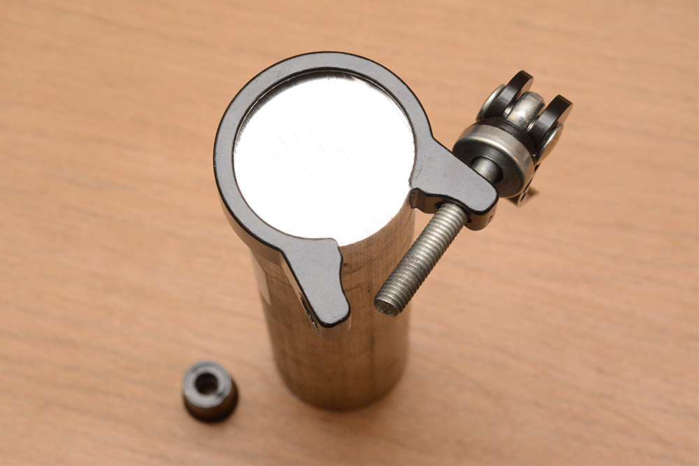
We could give it a longer bolt, but the flats on the clamp still wouldn't be parallel. Besides, I think the bolt is the most intricate part of the clamp and remaking it would make less sense than remaking the rest.
Note: Later I found out you can get QR clamps for 35mm. They're a bit of a speciality item, compared to the standard seatpost ones which cost less than their own postage. Still, if I'd known about the bigger clamps I would have gone for one.
Another note (2020-11-03): Ack! Turns out that 34.9mm is a standard seatpost size, so 34.9mm quick release clamps are quite easy to come by. D'oh!
Cutting
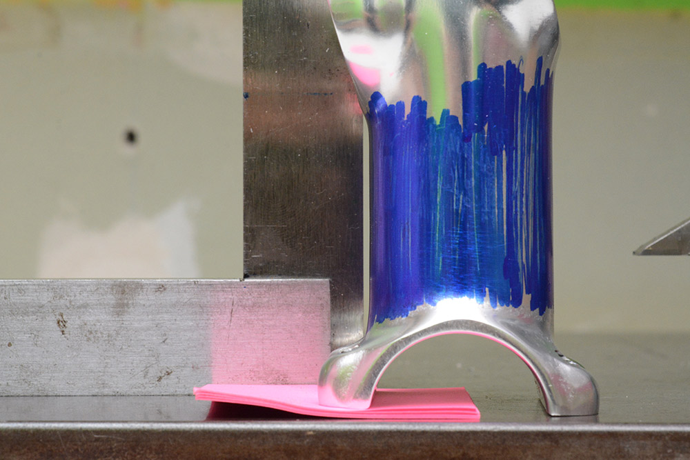
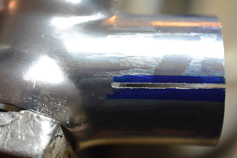
The stem is just all angles, everywhere.The first step is to strip the paint, cover it in layout sharpie, and scribe a line for cutting. I was somewhat depending on the handlebar end of the stem to be perpendicular, but as soon as I got to the surface plate it became obvious that wasn't the case.
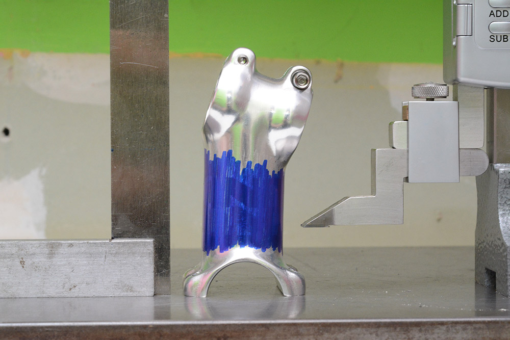
I used a stack of post-it notes as a shim to bring the thing visually up to vertical.
I'd planned to chuck it in the mill and use a thin cutting disk, but given how awkward the prospect of holding it now seemed, I gave up and went with a hacksaw.
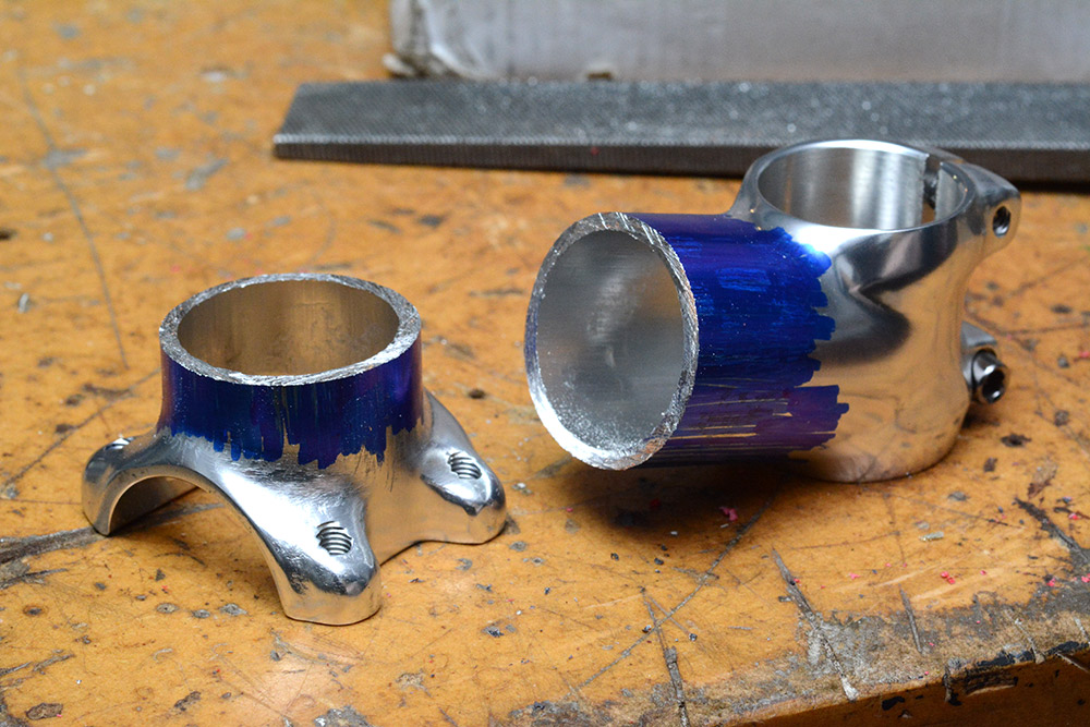
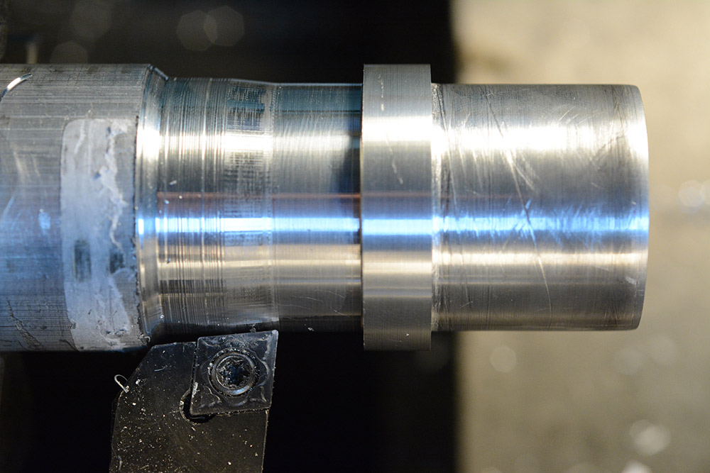
Turning
We want to make a section that'll fit inside the stem, welded to one half, clamped by the other. Simple lathe work.
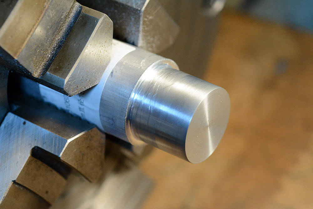
The inner diameter of the tube is 30.35mm. I approached it very slowly. I also gave the part a slight taper on the end, to match the slight taper in the bore. Eventually, it fit snugly.
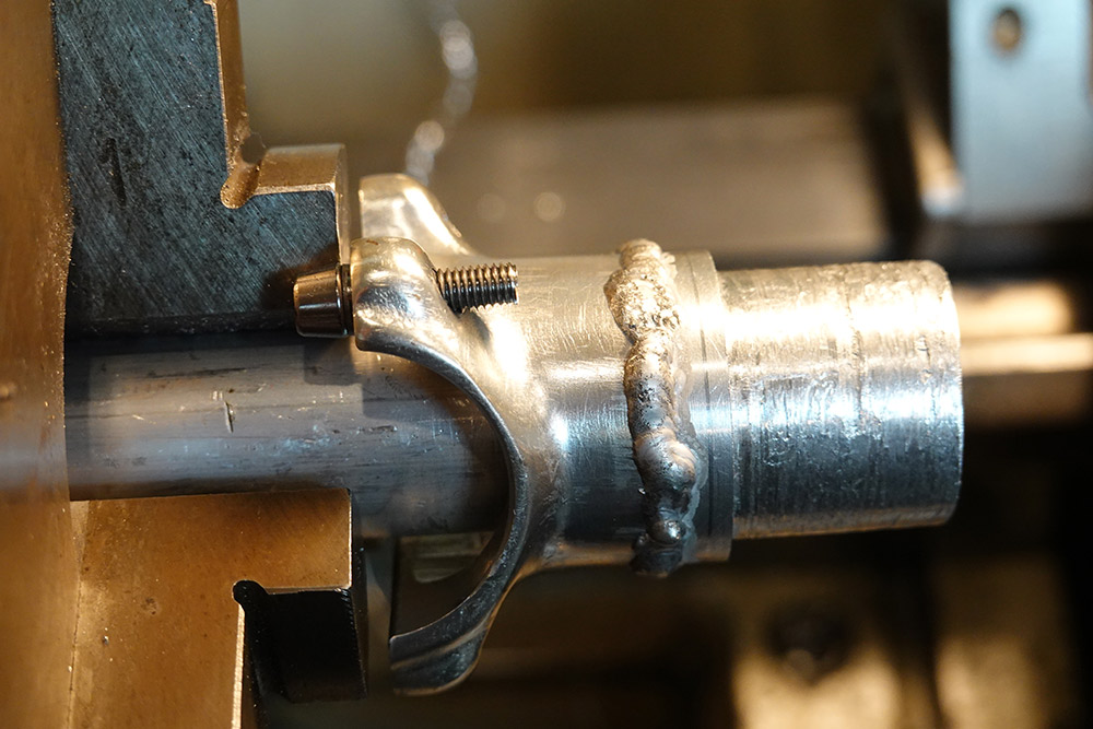
I'm using the four jaw because I want to reclamp it really accurately later on. The outer diameter is exactly the same as the stem (I'm a cheapskate, and the next diameter stock was about twice the price) so a very light skim cut is all we want to do.
After extending the stock out further, we dial it in from the freshly machined surface, then work on the other shoulder. Using a symmetrical tool to rough it out, we then clean up the shoulder with the left-hand turning tool.
The diameter needs to be a snug fit again. If anything, I really didn't want to overshoot and have it loose, so I left it 50 microns oversize. We can't test the fit until it's parted off, of course.
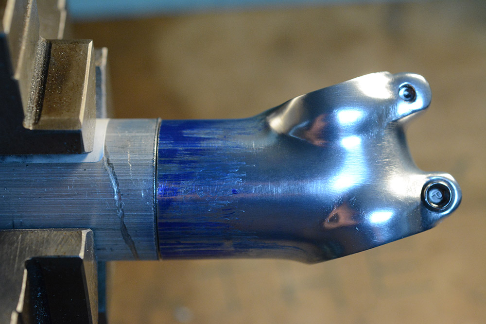
Turns out I made it a very tight fit. It took a lot of whacking with a hammer to get it snug. I don't think these two parts are coming apart.
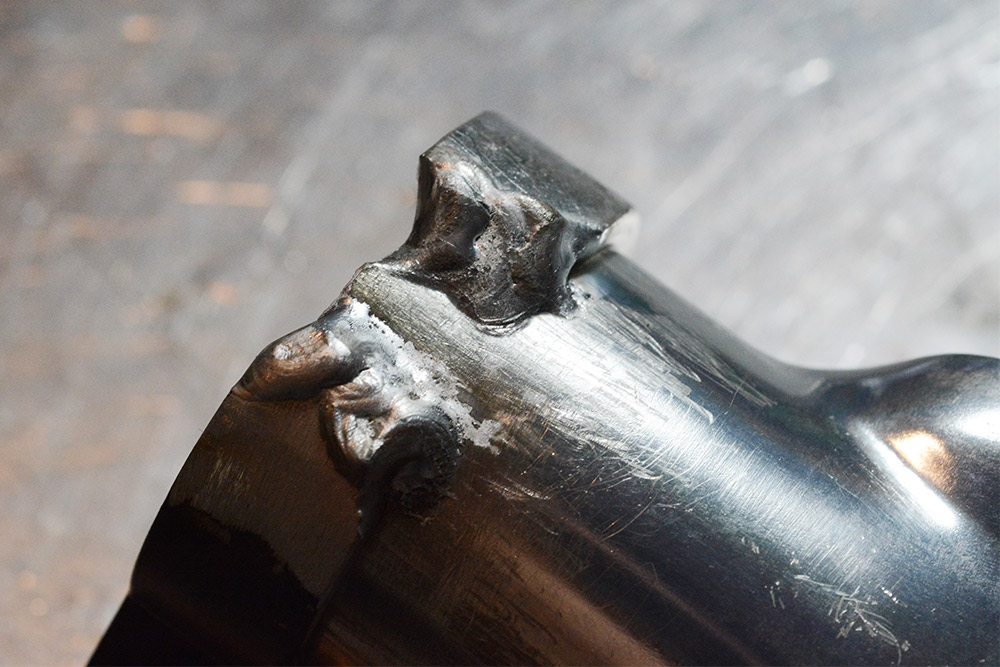
Of course I'm still paranoid and I'm going to weld all the way round regardless. The extra material gives us plenty of room for welding, and also makes up for the lost length from where we sawed it, and the fact this stem was overall shorter than the original.
Welding
It doesn't have to be pretty, but it really really really needs to not come apart.
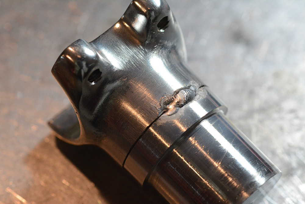
Aluminium is renowned for being difficult to weld. If we had a rotating fixture maybe we could produce a perfectly uniform weld bead. As it is, I have to stop and move the part every few centimetres. Yes, it's definitely the lack of a fixture that explains the unevenness of my welding...
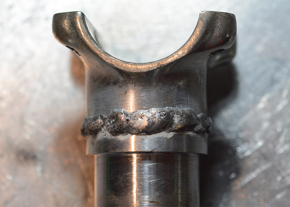
Honestly I'm pretty pleased with that, I was expecting it to look much worse.
The clamp! The clamp!
I was still pondering what to do here.
I think the best bet is to cut the clamp ring, and weld it in two places. But first I need to make the relief cut so it can actually clamp. Again we're faced with a nightmare trying to hold this part in the mill, so I ended up just hacksawing a slot.
Will this be the source of stress fractures down the line? Will we even live long enough to find out?
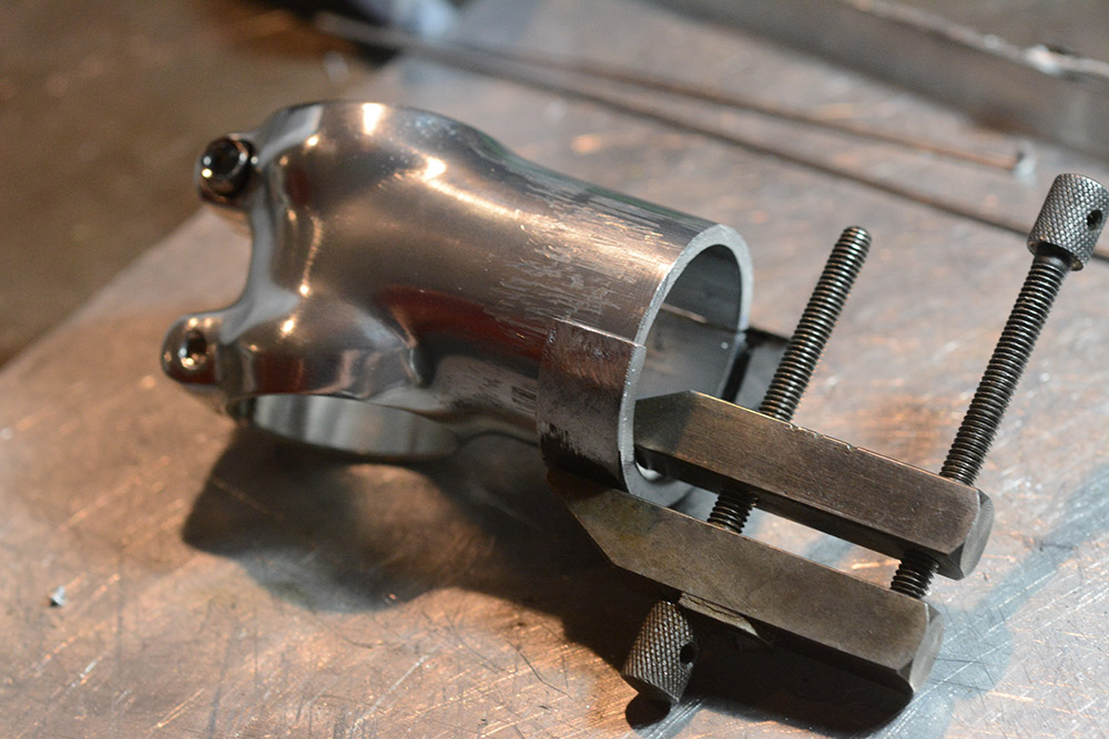
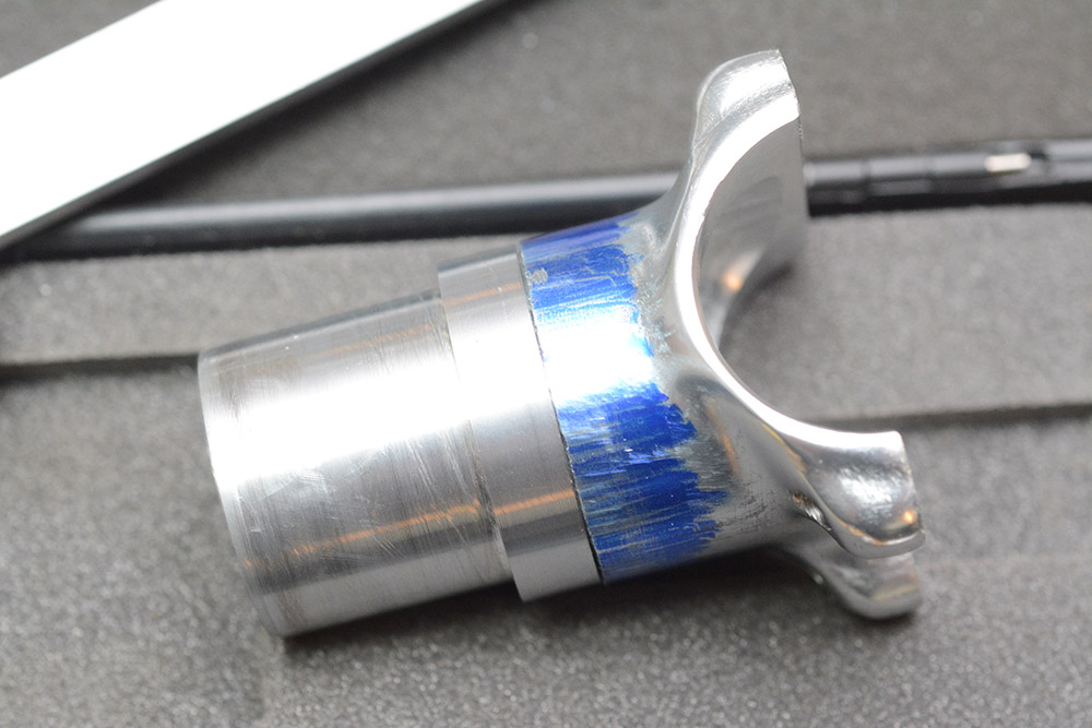
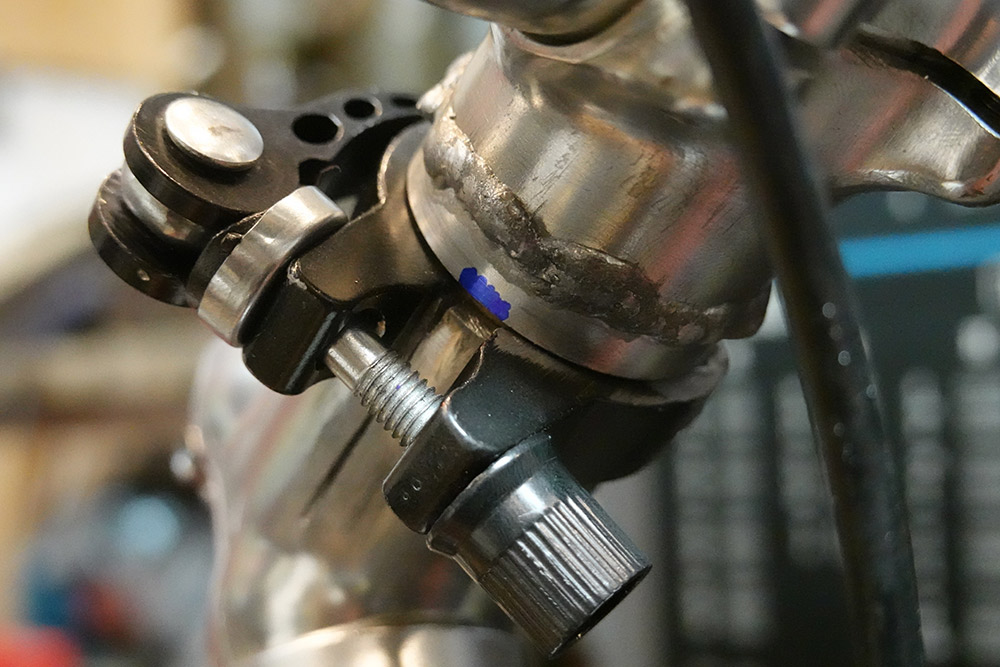
I cut the clamp ring, linished back the anodizing layer and then clamped it in place with yet another clamp. The welding needs the part to be grounded well, which is difficult here since all we've got is a tiny point contact. I found some heavy steel and draped that on top, which may have helped. At least it increased the pressure on the aluminium contact area.
Pretty it aint. Unlike before, where we had a solid mass to weld to, here the thin wall tubing is liable to blow out. That nearly happened in one place.
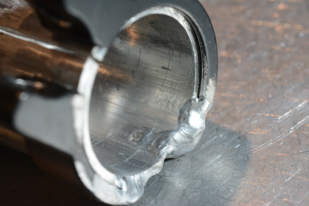
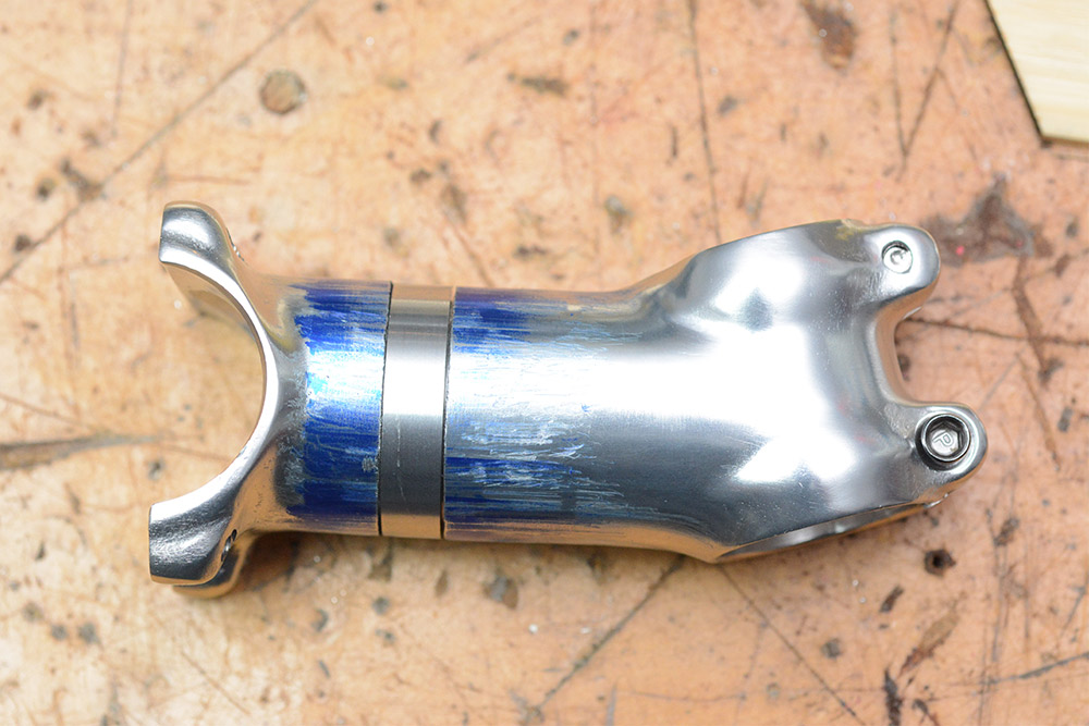
But will it clamp??
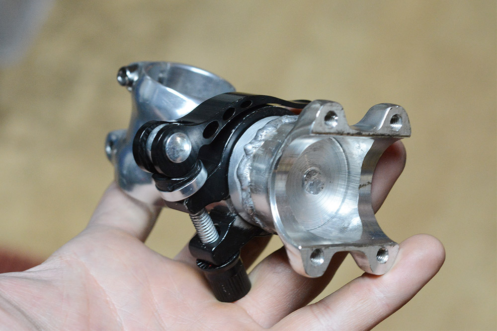
Yes, it clamps!
In the view above you can see the solid aluminium core is unfinished. The plan is to chuck this back in the lathe later on, where we can hollow it out to save some weight. If a sub-3mm wall thickness is sufficient on a manufactured stem, I'm sure we can hog away most of the core without compromising strength. That's a task for later though.
First I want to add either a detent or a hard stop, so that rotating to horizontal snaps to the right alignment. I think this is as simple as milling a cutout in the core, and adding a small pin into the wall of the stem.
But more importantly, before we do anything else, I want to try it on the bike and see whether we're anywhere near something workable.
First tests
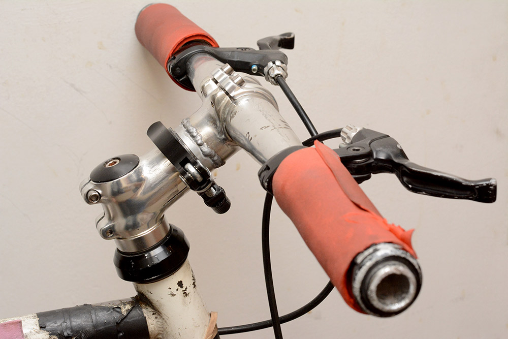
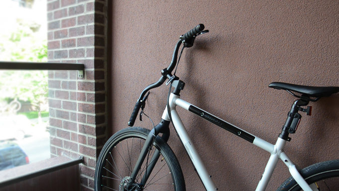
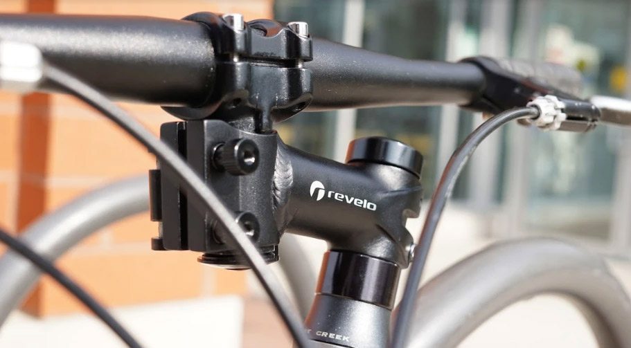
Squee! Just like a real bike stem. While it's not impossible that I grind the welds down later, the handmade look of the thing fits in pretty well with the overall look of the bike.
How about in the folded position?
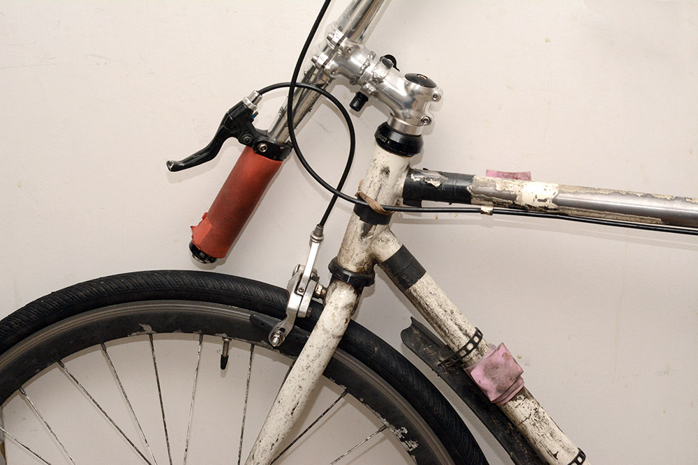
Clears the tyre by about a centimetre – it's almost as if I carefully planned this. The bike is flat against the wall, the pedals are now the widest part.
If you're alarmed by the damaged paintwork, torn electrical tape, rubber bands and bits of EVA foam that my bike appears to be held together with, let me assure you that this is all part of my elaborate anti-theft mechanism.
With the clamp fully tight, using my full strength and the full leverage of the handlebars I am able to rotate it a little bit. I think it's very unlikely to move during regular riding, but maybe some steep hills could cause a problem. The solution is to add a hard stop, or key slot, which prevents the rotation before the clamp is tightened.
A bigger problem became apparent after switching back and forth several times. The movement got progressively stiffer until it became really quite tricky to rotate even with the clamp loosened. It seems that the aluminium surfaces really don't like rubbing together. Pulling it apart, my nicely machined surface had become completely galled up.
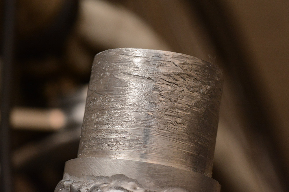
I filed it down a bit and tried some more, but it quickly jammed up again. Hmm, I hadn't anticipated this problem.
I think the next step is to machine a bushing to go between the surfaces. A steel ring should work, since steel-on-aluminium shouldn't have this problem. Perhaps even brass. If the core was turned down somewhat, and the ring fitted over it, it could be attached permanently and form the new clamping surface. I may research this further before I embark on it.
In the mean time, I'm going to try riding the bike a bit and seeing if I die. I'll update this project page when I next make progress on the stem. If it's been ages and the page has still not been updated, it's probably because the welds failed and I crashed and died.
Update
It's a few days later and I've a few things to report. First, I'm not dead.The clamp loosened a bit over the first day or so, I'm not sure if it stretched a bit or if it was simply "settling" but I found I had to add another turn to get it tight.
The galling on the aluminium only got worse so I pretty much had to do something about it now or never use the QR mechanism again. I figured the best thing to do was chuck it up in the lathe, take a skim cut, and wrap the surface in some brass shim stock. The best combo would be phosphor bronze on hardened steel, but brass on aluminium should still work wonders compared to before.
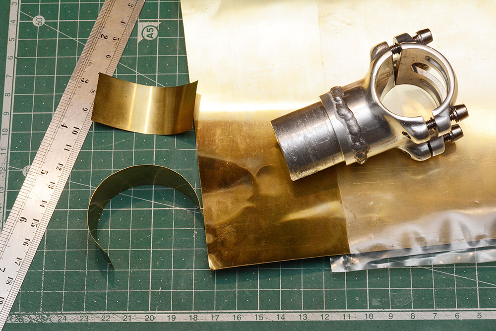
The shim stock is 0.005", or 0.127mm, so we can skim 0.254mm off the diameter. The galling gouged groves easily 0.5mm deep, so I'm not expecting it to clean up fully. And before we can even start we need a new way to hold the welded part in the lathe. Time to add the lightening holes I'd planned from the beginning.
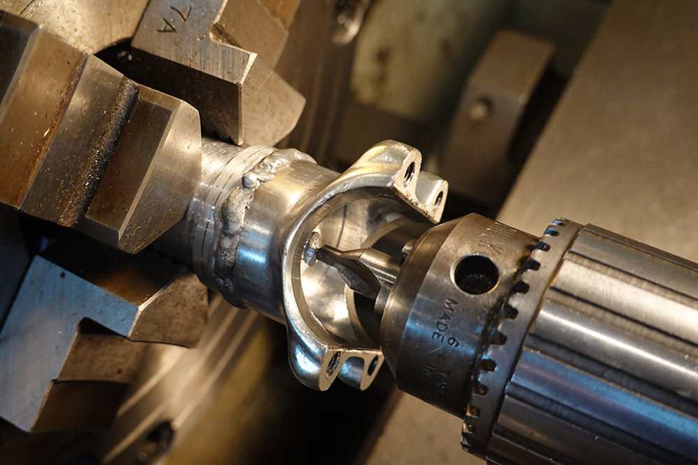
Holding it by the only surface even remotely grippable, I started the slightly terrifying process of hollowing it out. The four jaw is used so we can dial it in from the remaining machined surface behind the weld bead.
After drilling we switch to the boring bar, because I don't have any larger drillbits. 10mm is just barely enough to squeeze the bar in, and because of the clamp geometry we need as much stickout as we can get. The result is extremely prone to chatter.
When enough lightness had been added, I changed back to the three-jaw, chucked up some random bar stock, and turned a matching shoulder.
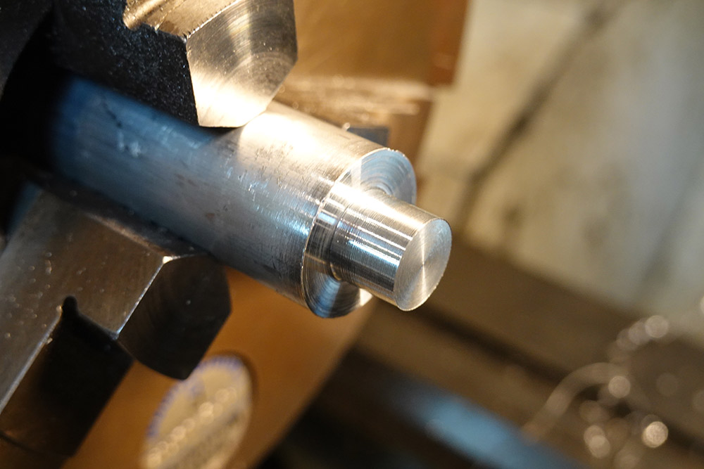
Now, at last, we can snug the part onto this shoulder, and use one of the bolts as a lathe dog.
To be on the safe side I rammed the tailstock live centre up against it. The part isn't going anywhere. We've got just enough room – by a hair's breadth – to turn the galled surface. Awful lot of work just to take a skim cut, eh?
![]()
This was actually a pretty good setup as it allowed me to quickly move the part between the lathe and the bike. See, after the first skim cut, the parts mated nicely, even with the shim. But when I rebuilt the bike, it jammed.
It turns out that as you tighten the pinch-bolts of the stem onto the steerer tube, the stem distorts, with the main tube becoming slightly elliptical. This, no doubt, is the source of most of my problems.
I skimmed the diameter again until it fit, with the shim, into the remainder of the stem while the pinch-bolts were tight.
At last we had free rotation, and after a dozen or so oscillations there's no sign of wear. Unfortunately, the brass surface reduces friction enough that even maximum clamping force is no longer sufficient to keep the handlebars level. I noticed that the hacksawed slot in the stem was fully closing when the clamp tightened. Using a needle file, I widened the slot a bit to see if we could extend the range, but it didn't help.
The next task, evidently, was to make a key that locks the rotation properly.
Key (attempt 1)
The goal here is to have a short keyed section, so that loosening the clamp involves two steps. One, undo the QR lever; and two, pull the bars forwards slightly to free the key. The distance pulled forwards should only be a few mm.My original plan for a key became unappealing when I realized how hard it is to hold the parts in the mill.
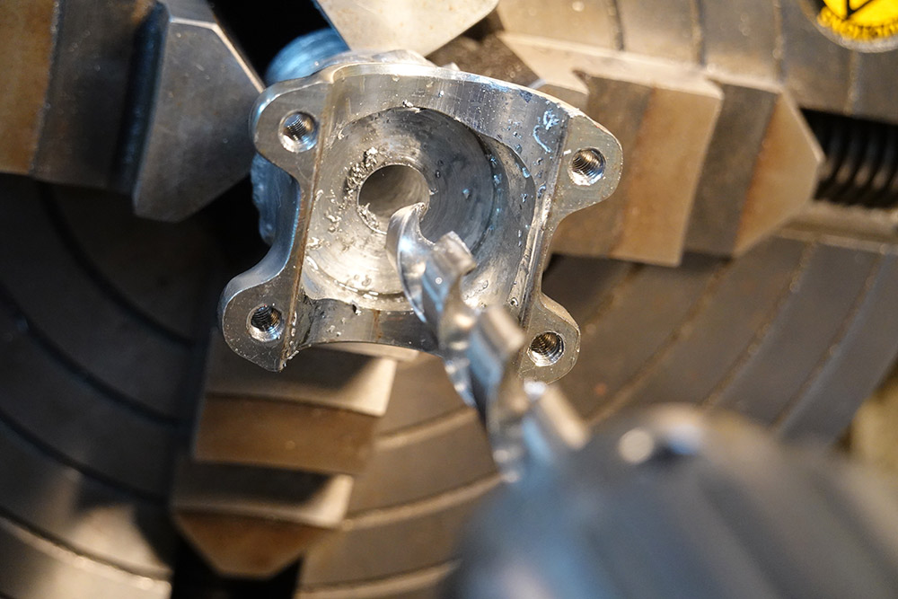
I figured a much simpler key could be made to fit the pre-existing slot where the clamp halves join.
I attempted to mill a slot with a 2mm endmill. With the part in a v-block I still couldn't quite manage it.
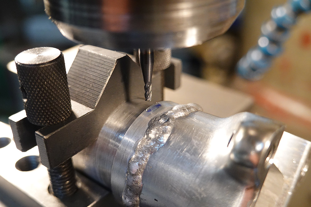
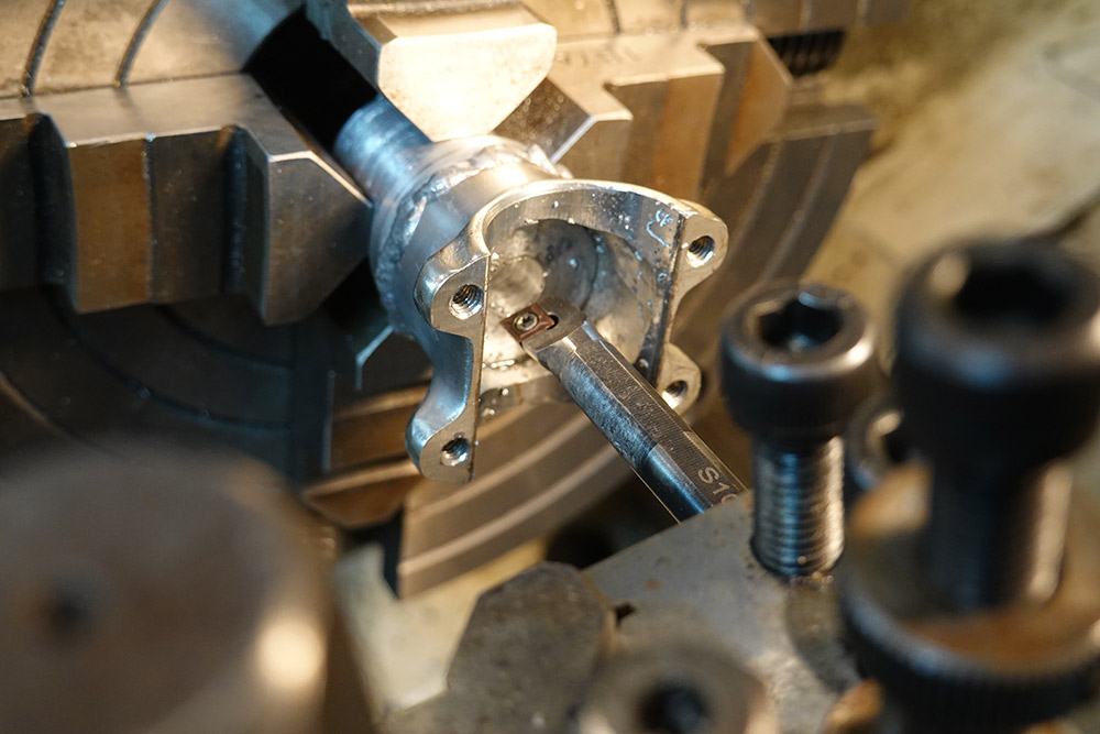
I ended drilling two deep holes with a 2mm drillbit, and chiselling out the remainder with a thin bit of tool steel.
I cut a strip of stainless sheet to act as the key. In the picture below, I've positioned the key ready to be hammered into place. The slot is full depth, so it should be possible to sit the steel key flush.
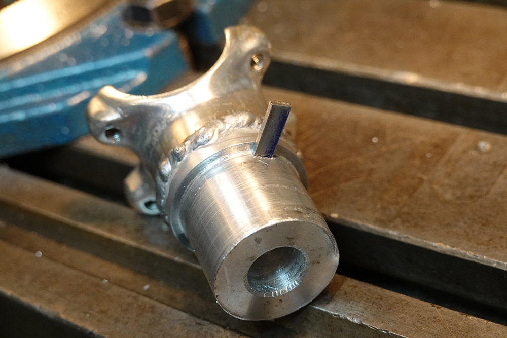
Unfortunately this key was never going to work. As soon as I fitted it, and tried putting some torque on the handlebars, it immediately deformed the aluminium in the clamp section. Just a millimetre of deformation means a few degrees of slop on the bars. I'm sure that if I stuck with this key, that'd only get worse, and possibly the clamp would lose strength.
Reluctantly, I removed the key and went back to the drawing board.
The design needs the key to only grab on a few millimetres of surface, so I think any key in aluminium will have problems. Steel on steel would have been fine. Another option would be dog-teeth, basically fitting many keys all the way around. If they were machined precisely, the load would be shared and perhaps the aluminium would be strong enough. But, the effort to produce this would be colossal.
The original key idea was to mill a slot all the way along the back of the core, and place a bolt through the stem. I think this is less likely to fail than the first key attempt. Perhaps milling a cross section into some more aluminium stock and fitting that inside the stem, which would mate with a cross milled in the back of the core. Another reason I'm reluctant to do this is it'll likely mean weakening the stem further by adding bolt-holes.
Shimtacular
This week England is going back into lockdown so it's likely I won't have access to the metal workshop for a while. As a temporary fix for the lack of clamping force, I added an extra shim between the brass and aluminium – a strip of ordinary paper.It feels offensive to be using a piece of paper in an application like this.
But the paper compresses perfectly to the gaps in the aluminium stem section and massively increases the friction on the brass. The result is a clamp that's perfectly usable, while still letting us smoothly swing the bars when we want to.
The clamping force isn't perfect, and the bars still shift a little when I pedal hard. I'm also wary that the paper might just disintegrate. I've no idea if it's waterproof. But I'll keep cycling on this setup until I'm able to produce a proper key system.
Update (2023-02-15)
It's been a few years since I built this QR stem so we're well overdue for an update. First – and I'm as surprised as anyone to announce this – I'm still not dead!A few weeks after fitting the shim of shame, I fiddled with it again, making a new sandwich of brass and paper. I got it about right, and it's lasted ever since. I have a habit of really gronking it when the lights change, and with my full strength sometimes the bars would move, which is unnerving but not as catastrophic as you'd expect. After a few months though, the mechanism got a bit stiffer and it doesn't seem to happen any more. I spent about a year riding this most days and folding it up for storage. Top notch!
In late 2021 I moved house and I now have a dedicated place to chuck the bike, so I haven't needed to use the folding mechanism so much. I still show it off whenever I can though, most people either love it or don't understand it at all.
Someone linked to this project under "Hacks / Bodges" on a forum called LFGSS. The entire thread is fantastic, some of the bodges are absolutely hilarious. I wasted a good few hours browsing through it. And in response to the welding on my QR Stem, someone replied "It's awfully close to doing it properly and not belonging on this thread." — I'm honoured!