
Mk IV User manual
2 May 2025This is the user manual for the Precision Clock Mk IV. See also the assembly instructions for the kit and the project page about its development.
- Basic Use
- Buttons
- Configuration
- Modes
- Zone Override
- USB serial output
- Matrix frequency
- Colon animations
- Accuracy tolerance
- Brightness Curve
- Updates
- Flash memory
- Coin cell
- USB re-enumeration
- Error messages
- Time-only clock
- SWD/debug interface
- Bootloader user request
- Antennas, wall mounting and other modifications
Basic Use
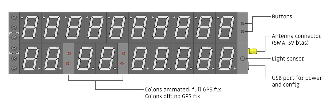
Connect a GPS antenna to the SMA connector, and power the clock via the USB cable.
For a cold start, with no coin cell or if it's just been fitted, the clock will show approximate UTC time until it finds a full GPS fix. Once it gets a fix, it should update to show local time with full precision.
If you fit the coin cell, it will keep time while powered off, and be able to do a warm start, finding the GPS fix much faster.
The colons will only illuminate if it has a full GPS fix (PPS active). If it loses its fix, the colons will stop blinking. After 1000 seconds (about 15 minutes) without a fix, the milliseconds digit will go blank, and after 10000 seconds the centiseconds digit will go blank.
In other words, the tolerance of the current time display is shown by the amount of precision on the display. The time is only right to within a millisecond if the millisecond digit is ticking.
Buttons
The two buttons on the clock cycle back and forth through the enabled modes. By default, only three modes are enabled: standard ISO8601 display, detected UTC offset and timezone name.
As of firmware 0.0.3 (2026-02-19), you can hold both buttons down at the same time to reset the clock.
Configuration
All configuration of the clock is done via the USB port, which enumerates as both a mass storage device, and a serial port. The mass storage device contains a file called config.txt which should be fairly self explanatory.
You can find a fresh (template) copy of the file here.
The file contains a list of parameters in key = value format, with lines beginning with # ignored. The on/off values are relaxed about syntax (you can either specify 0/1, on/off, enabled/disabled) and it's case insensitive.
Any config listed in the file can also be sent via USB-serial. If you enable a mode this way, it will immediately switch to that display mode. Commands over serial are temporary, if you power cycle the clock it will load from the config file again. There is one special command via serial not available in the config file: reboot.
Modes
There are lots of different modes, so to keep things simple most of them are disabled by default.
There are just two buttons on the clock, and these cycle back and forth through the enabled modes.
| MODE_SHOW_TZ_NAME | Attempt to display the IANA timezone name on the 7-segment display, such as Europe/London, etc. This is usually somewhat illegible, particularly as it can't display the "m" in America, but it's enough to confirm the auto-timezone is working (or, if you've overriden it via the config, the zone override is working). |
| MODE_SHOW_OFFSET | Display the UTC offset of the current local time. This overrides the whole display. Naturally it would have been nice to have an additional four or five digits on the display to show this all the time, but it would have made the clock even wider! |
| Date formats | |
|---|---|
| MODE_ISO8601_STD | YYYY-MM-DD Standard ISO8601 / RFC3339. |
| MODE_ISO_Ordinal | YYYY-DDD ISO8601 ordinal (day of year) |
| MODE_ISO_WEEK | YYYY-Www-d ISO week date. The ISO week-numbering year is slightly offset to the Gregorian year. On the 7-segment display, the W is poorly rendered, but hopefully unambiguous. |
| MODE_UNIX | Unix timestamp, in decimal; the number of non-leap seconds that have elapsed since 00:00:00 UTC on 1 January 1970. |
| MODE_JULIAN_DATE | Julian Date. The number of days (plus fraction) since the Julian period epoch. Not that the date display of the clock is only updated once per second. |
| MODE_MODIFIED_JD | Modified Julian Date (Julian Date minus 2400000.5). An easier to manage version of Julian Date that drops the first two digits and increments at midnight instead of noon. Note that the fraction is approximate: the date display of the clock is latched at the start of the UTC second, not the fractional increments of MJD. |
| MODE_WEEKDAY | Show weekday, within the limitations of the 7-segment displays. "M" and "W" are rendered poorly. |
| MODE_WEEKDA_DD | Show weekday and day-of-month. The missing Y is to remind us that some of the weekdays will be truncated, e.g. "Wednesd 08". Added 2026-04-08. |
| MODE_WDY_MM_DD | Truncated weekday, month and day-of-month. "Wedn 04-08". Added 2026-04-08. |
| Special modes | |
| MODE_STANDBY | Turn off the whole display. This mode can be useful if you want to reduce power consumption but keep the clock/GPS module fully powered. If you're running the clock from a USB battery bank, you may have to activate a mode on the battery to keep it supplying power when the current has dropped to almost nothing. |
| MODE_TEXT | Generic text display. The text displayed is loaded via the TEXT= command. As with all the commands, this can be sent via the USB-serial interface, so it could even be used to implement a custom date format handled by an external script.Currently, only one decimal point may be illuminated at a time. This will be fixed in a later firmware version. |
| MODE_COUNTDOWN | Turn the clock into a high-precision countdown timer, showing the number of days, hours, minutes, and seconds until the epoch specified by COUNTDOWN_TO. With the current firmware, the epoch must be specified as a UTC timestamp in ISO8601 format, with the T in the middle, no fractional seconds, and the trailing Z.E.g. 2023-05-06T23:00:00Z |
| Debug modes | |
| MODE_FIRMWARE_CRC | Display the CRC of the loaded firmware images, in hexadecimal. This enables two separate display modes, one for each firmware image, with the values preceded by a t and a d for the time and date sides of the clock respectively. |
| MODE_DEBUG_BRIGHTNESS | Shows input and output values of DAC/ADC. The separate command brightness= can be used in conjunction, more info further down this page. |
| MODE_DEBUG_RTC | Show remainder of RTC calibration after 63 second period, added purely to aid with the implementation. |
| MODE_SATVIEW | List number of satellites in view. Note that this is just the number of satellites, not their signal strength, but gives a very basic idea of whether the GPS module and antenna are working. First number is GPS satellites, which are used to derive the timepulse. The next letter/number is the secondary constellation with the most satellites in view, where L represents GLONASS, A represents GALILEO, and b represents BeiDou. |
| MODE_VBAT | Display the measured voltage of the coin cell battery. |
| MODE_DISPLAYTEST | Test all segments of the display. First illuminates digits 0-9 on all displays, with the colons toggling, then illuminates all segments of each display in sequence. Note that not all decimal points are expected to illuminate, the first five digits on the time side don't have them connected on the PCB. Also note that to debug the decimal points, the clock should be unfolded, or the date side will automatically shift their positions.
This was added 2025-10-26, so you may need to update the firmware to enable it. |
| MODE_TTFF | Time-to-first-fix. If enabled, the clock will power up into this mode and count the minutes and seconds until GPS valid with PPS. Specifically for testing lots of GPS antennas in parallel. Note you have to keep this mode selected for the value to be accurate. |
Zone Override
The timezone is detected automatically from the GPS position. If you want to display a specific timezone instead, use this parameter. You will need to use the exact IANA timezone string, case sensitive.
ZONE_OVERRIDE = America/New_York
Comment out the line to leave it automatic. For UTC display, use:
ZONE_OVERRIDE = Etc/UTC
The full list of zones is provided in timezone-names.json. If you are sending commands via serial, you can disable the override by setting it to something invalid (like zone_override = off).
It's also possible, for debug purposes, to send a fake GPS coordinate with fake_longitude = and fake_latitude = commands. To disable this, set both coordinates to exactly zero.
USB serial output
When connected to the USB serial device, in addition to typing commands, the clock will (by default) output the NMEA strings it's receiving from the GPS module. This generally appears as a wall of text. If you want to use this as a time source, you will also need to wire up a connection to the PPS output of the module. I did experiment with sending PPS via DCD over USB state commands, but the jitter was sometimes several milliseconds, which defeated the purpose.
You can filter the output by using the NMEA = RMC command, which shows only the RMC message. You can also turn it off with NMEA = off or re-enable full output with NMEA = all
To make better sense of the information, you can feed it into the "u-center" software from u-blox (manufacturer of the GPS receiver). It is Windows-only software but works acceptably under wine. It can plot satellite information, sky view, and so on. However, you cannot configure the GPS module this way, commands will not be forwarded to it. If ever that becomes necessary, I might add it in a later firmware update.
Matrix frequency
This is the speed of the display refresh, in Hertz, from 1000 to 100000. The default is 20000, and unless you're using the clock for high-speed photography there's generally no need to change it. At below 20kHz, there's a potential risk of electroacoustic effects, though I haven't noticed anything in practice. At higher speeds, there's a potential for electromagnetic interference, though again this hasn't been measured.
The display is split into four matrices of 5 digits each. The number given here is the refresh rate of the display – the clock frequency of the matrix will be five times this number. Note the specified frequency is only a target, the exact frequency will be a division of processor clock speed. At high values, there's a chance the date and time sides of the display will be slightly different frequencies.
MATRIX_FREQUENCY = 20000
Colon animations
For the previous generation of clock, some people complained about the blinking colons, so for this one I made sure to be able to customise the animation. Remember that the colons carry information: if they stop blinking it means the GPS fix has been lost.
Currently supported modes are: slowfade, heartbeat, sawtooth, alt_sawtooth, toggle, solid. More animations may be added at a later date.
COLON_MODE = heartbeat
Accuracy tolerance
The dynamic precision disables the last digits of the clock to reflect situations with reduced accuracy. The assumption is that the onboard TCXO keeps time to within 1ppm. That may not be entirely true, or you may simply have trust issues about it, or you may want to replace the oscillator with a different 10MHz source. You can change the tolerances for the dynamic precision in the config file.
Tolerance_time_1ms   = 1000
Tolerance_time_10ms  = 10000
The deciseconds digit is only disabled if the clock has been powered off and the last RTC calibration was more than this many seconds ago.
Tolerance_time_100ms = 100000
Brightness Curve
A nonlinear mapping between the light sensor and the display voltage is possible. A special display mode, MODE_DEBUG_BRIGHTNESS will plot the exact values at the ADC and the DAC. You can use this, in conjunction with the brightness curve GUI, to set up the brightness curve to work with different LEDs or light sensors.
While debugging, it can be useful to use the command brightness = n where n can be either a floating point between 0.0 and 1.0, or the integer value up to 4095. If sent via the USB serial, it immediately disables the brightness curve and updates the display to that brightness. This can also be useful if you are trying to film the clock, and want to lock it to a fixed brightness.
Example brightness curves
The light sensor forms a potential divider with resistor R11. On Rev C circuit boards, R11 is 20K and the light sensor is GL5528. There's also a capacitor, C21, which provides smoothing. On Rev C, C21 is 1uF.
Rev D boards use a phototransistor, part number VTT9812FH. It needs R11 to be 470K, and to keep the smoothing in the right ballpark, C21 is changed to 100nF.
Here are some curves I've experimentally found to give similar behaviour for different parts:
# default curve for Rev C: GL5528 and R11 = 20K
BS1 = 0,0
BS2 = 1425,737
BS3 = 2566,1601
BS4 = 3396,2725
BS5 = 4095,4095
# GL5549 with R11 = 470K
BS1 = 0,0
BS2 = 1860,225
BS3 = 3050,684
BS4 = 3920,2269
BS5 = 4095,4095
# suggested curve for Rev D: VTT9812FH with R11 = 470K
BS1 = 0,0
BS2 = 131,365
BS3 = 1076,1422
BS4 = 2774,2665
BS5 = 3849,4095
Updates
Periodically the timezone and map data may need to be updated. You can find the latest releases here. The attached zip file has a directory called "flash" containing the updates.
For timezones, simply copy the relevant files (tzrules.bin and tzmap.bin) onto the mass storage device. The process will be quite slow, as the clock gives priority to the display stability over the USB interrupts. (This was a conscious decision, knowing it would make copying files slower, but it's worth it to ensure the display doesn't jitter during the transfer!)
For firmware updates, copy the relevant files onto the device (fwt.bin and fwd.bin). You can trigger the update immediately by ejecting the USB device, or you can disconnect and re-connect the clock, it will update at the next power on.
In all cases, you'll want to overwrite the existing files on the disk. The clock looks for those specific filenames.
The last few bytes of each firmware image have information about them. You can view this with a hex editor or hexdump utility.
$ hd fwt.bin | tail
00018420  43 49 49 00 00 00 00 00  00 00 00 00 00 00 00 00  |CII.............|
00018430  00 00 00 00 00 00 00 00  00 00 00 00 00 00 00 00  |................|
00018440  ff 00 00 00 00 00 00 00  00 00 00 00 00 00 00 00  |................|
00018450  00 00 00 00 00 00 00 00  00 00 00 00 00 00 00 00  |................|
*
0002ffc0  42 75 69 6c 64 20 32 30  32 34 2d 30 35 2d 32 39  |Build 2024-05-29|
0002ffd0  54 30 30 3a 31 38 3a 35  30 20 56 65 72 73 69 6f  |T00:18:50 Versio|
0002ffe0  6e 20 30 2e 30 2e 30 20  00 00 00 00 00 00 00 00  |n 0.0.0 ........|
0002fff0  00 00 00 00 00 00 00 00  00 00 00 00 e2 ea 8a a2  |................|
00030000
The last four bytes are the CRC.
Flash memory
The format of the storage is very important. If the device gets corrupted, don't simply re-format the drive with the default options. The memory must be formatted FAT12 or FAT16, with block size of 4096 (not 512).
I have provided a bash script that formats the drive correctly and copies the relevant files onto it, but if you're unsure, the safest option is to download a prepared disk image and use a disk imaging utility.
A disk image is provided in the zip file for the latest release. There are various utilities (such as Win32DiskImager) that can be used to flash this to the clock. Note that this wipes everything including the config. If you have a Rev C clock you will want to update or delete the brightness curve in the config file, which currently is for Rev D.
There are more notes about setting up the flash memory here.
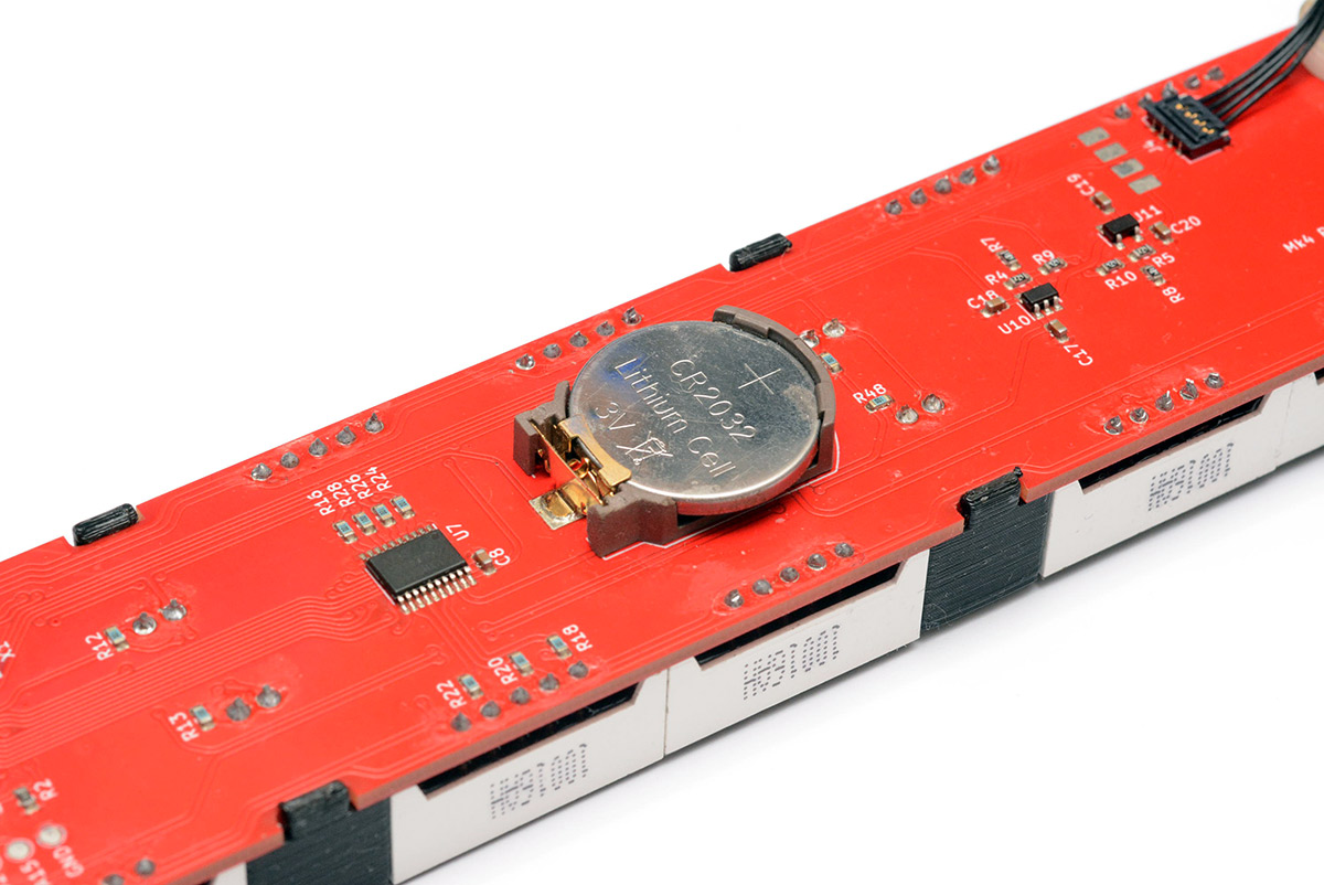
Coin cell
The CR2032 coin cell provides a battery backup to both the GPS module and the RTC. The cell should last a few years.
When the cell becomes empty, the RTC will eventually stop ticking. At that point, there may still be enough voltage to sustain the non-volatile RAM, so at the next power-on the clock will initially show a time that may be several hours or days in the past. If this happens, it's a signal that you need to replace the coin cell.
As of firmware 0.0.1 (2025-08-02), the battery voltage is checked on power-on, and display precision is reduced to whole seconds if it's below 2.70V. You can also use MODE_VBAT to check the voltage.
Replacing the coin cell is difficult, I deliberately chose a very secure holder as I originally envisioned the clock functioning as a clapperboard and didn't want it to be shaken loose. The easiest method is to insert a spudger or screwdriver under the coin cell and twist it while pulling back the gold tab with a fingernail. Don't be too forceful or you might rip the whole coin cell holder off the PCB.
USB re-enumeration
When you "eject" the USB device, normally via right-clicking in Explorer/Finder/whatever, or via the command-line eject /dev/sdX (which is different to simply unmounting), the clock responds by disabling its USB communication until the next power-on.
To reconnect to the clock without unplugging, as of 2026-02-19, you can hold both buttons down, which will reset the clock and re-enumerate the USB. This is very useful if you want to leave the clock connected to your computer but don't want the storage device and serial port to always be there. You can press both buttons, then play with the clock, and eject it after, all without powering down the GPS module.
If you've modified the clock to be powered from another source, for instance feeding 5V into the VBUS test pad, you can wire up the actual VBUS of the USB port to PA8 (pin 41) of the microcontroller, and USB will re-enumerate when reconnected. To do this you need to remove the ferrite bead FB3, and drop the voltage to a safe level with a potential divider.
Error messages
If the clock hangs, an error code will display, consisting of a letter and number.
| Bootloader errors | ||
|---|---|---|
| b0 Error | ERR_FATFS | Unable to mount / FATFS failure |
| b1 Error | ERR_FS_IMG_CRC_INVALID | fwt.bin image on file system fails CRC check |
| b2 Error | ERR_INVALID_NO_FW | Loaded firmware image is invalid and no replacement found in file system |
| b3 Error | ERR_ERASE_FAILED | Flash page erase failed |
| b4 Error | ERR_WRITE_INVALID | Data written to flash didn't match data read back |
| b5 Error | ERR_WRITE_FAILED | Write data to flash returned failure |
| b9 Error | ERR_UNKNOWN | Unknown (other bootloader failure) |
| Chainloader errors | ||
| d1 Error | ERR_FS_IMG_CRC_INVALID | fwd.bin image on file system fails CRC check |
| d2 Error | ERR_DATE_DEAD | No response from date side (check hinge cable) |
| d3 Error | ERR_GET | Date side system loader error |
| d4 Error | ERR_UNEXPECTED_TIMEOUT | Date side system loader error |
| d5 Error | ERR_VERSION | Date side system loader error |
| d6 Error | ERR_ERASE_FAILED | Date side system loader error |
| d7 Error | ERR_WRITE_PAGE | Date side system loader error |
| d8 Error | ERR_WRITE | Date side system loader error |
| d9 Error | ERR_GO_FAILED | Date side system loader error |
Time-only clock
If for some reason you want to use the clock without the date side attached, by default it will throw an error. You can suppress this error by deleting or renaming the date-side firmware file on the drive (fwd.bin).
Without fwd.bin present, the clock will not check for responses from the date side.
If anyone actually wants this, a future firmware update could re-purpose the hinge wires to directly function as the buttons to change modes, when the date side is not present. In the mean time you can still change modes via USB serial commands.
SWD/debug interface
There are test pads on both circuit boards to connect an ST-link adapter if you wish to develop custom firmware for the clock. You can either connect to these with a pogo jig (I have a clothes-peg style one) or surface-mount solder header pins to them. They are positioned so that they won't interefere with each other when the clock is folded.
One thing to note is that the date side of the clock uses the SWD pins as part of its display matrix. In order to connect, you can signal the firmware to not disable the SWD interface by holding down one of the buttons during power-up.
Bootloader user request
Because I tend to be paranoid about these things, a scenario occurred to me that would put the clock into an unrecoverable state, to wit, copying a firmware image onto the drive that passes the CRC but fails to enumerate a USB stack. The only situation where this could happen is if someone is developing their own firmware version.
I do most of my development using the SWD interface, but it's possible to simply build a new image, copy it to the device over USB, eject/reboot and test your new firmware. A short bash script makes this very convenient. However, it's then quite possible to make a mistake, potentially causing it to hang before enumerating the USB device, in which case you'd be stuck and unable to copy another image onto it. From there, even using the SWD interface to try and recover is difficult: you'd need to erase the bootloader completely, then flash a new firmware image without the bootloader, and use that to erase the file from the external flash memory, or else it would keep re-loading the corrupt file off of it.
For this exact situation, I've added a "user request" signal to cancel the bootloader, and hang after enumerating the backup USB stack. This allows you to edit the contents of the flash memory without trying to load and run the main firmware. To trigger it, short TX of the hinge cable to ground while power-cycling the clock. It's pin 2 to pin 4 on the hinge cable, where pin 4 is connected to the ground plane. Touching them with tweezers works well. The display should read bU Error.
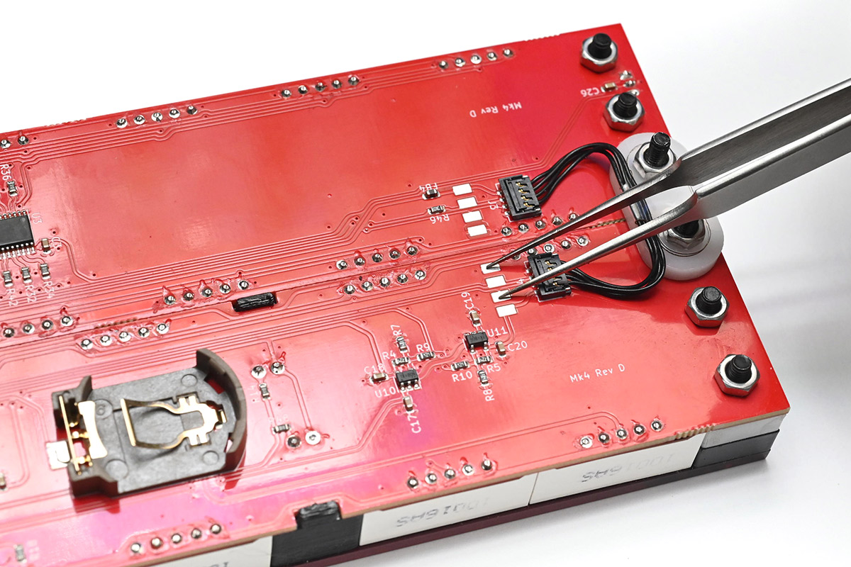
This was added to bootloader version 0.0.3 (2025-08-03).
Antennas, wall mounting and other modifications
These are listed on the instructions page. See subheadings for antennas, wall hanging, shelf stands, and tripod mount.