Mk IV Assembly Instructions
2 May 2025Assembly Instructions for the Precision Clock Mk IV.
Note: I've now designed an upgrade to the Mk IV kit which protects the face with tinted acrylic, but building it is more complex, and needs additional lasercut and 3D printed parts, along with different bolts and switches. I mention this just in case anyone hadn't seen it, and falls in love with the acrylic version. It's possible to adapt a fully assembled clock to have the acrylic case, but it's more work than setting out to build it initially.
If you want to assemble the kit but keep the possibility of adding the acrylic cover as easy as possible, I have marked a few steps with Acrylic Upgrade notes.
Tools needed
- Soldering iron
- 2.0mm Allen key / hex driver
- pliers or small wrench (5.5mm)
- sharp knife
- good lighting
- spudger, or any rigid plastic stick (a ballpoint pen works)
- isopropyl alcohol or another solvent for getting rid of sticky residue
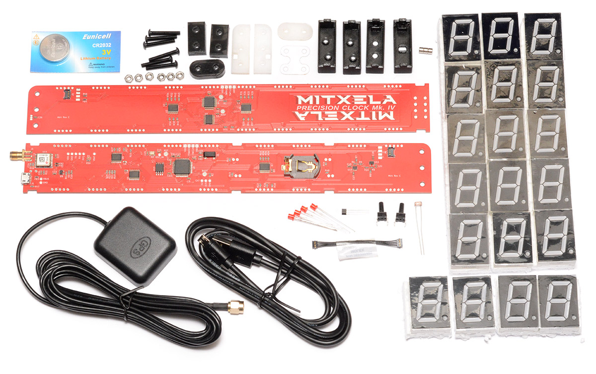
List of components
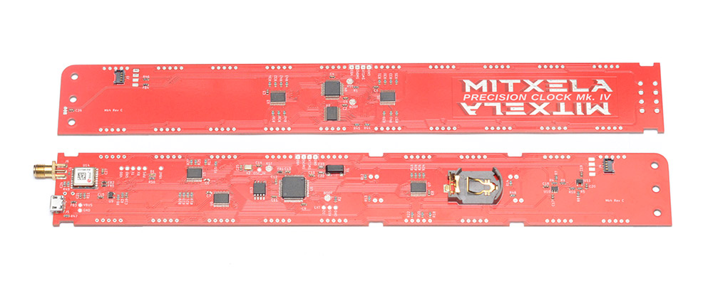
Two circuit boards:
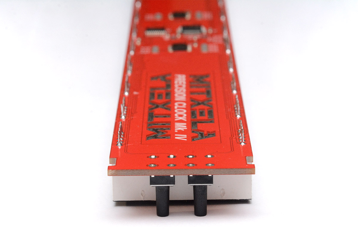
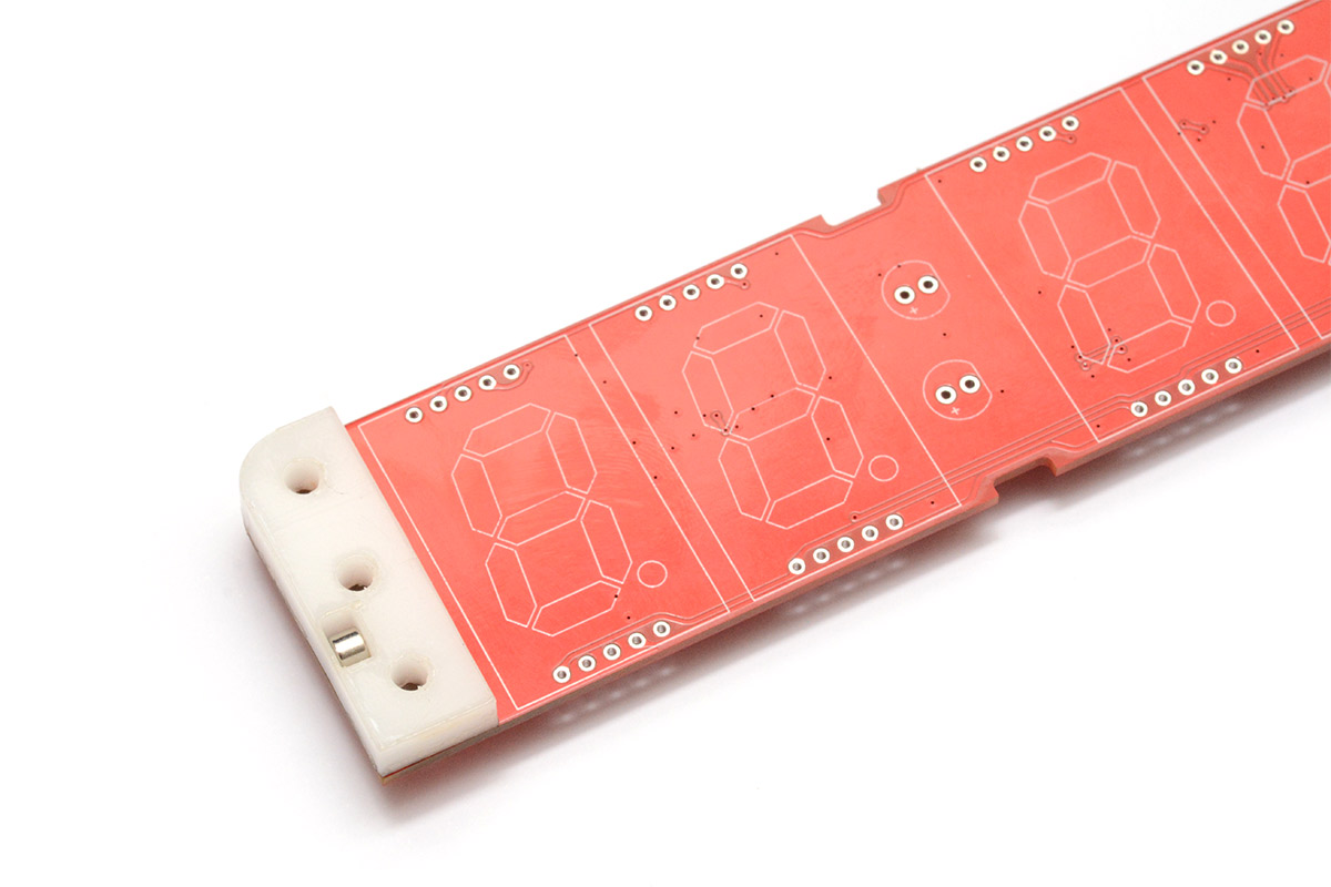
- the "date" side, has the logo
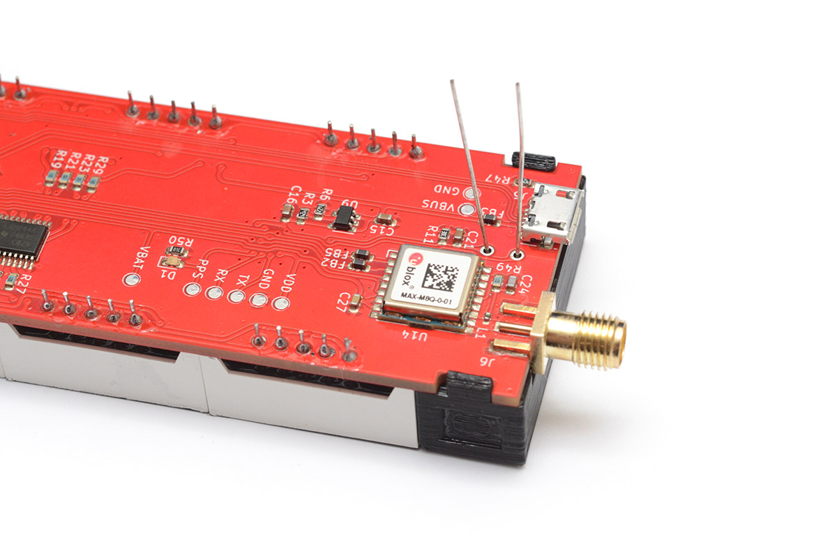
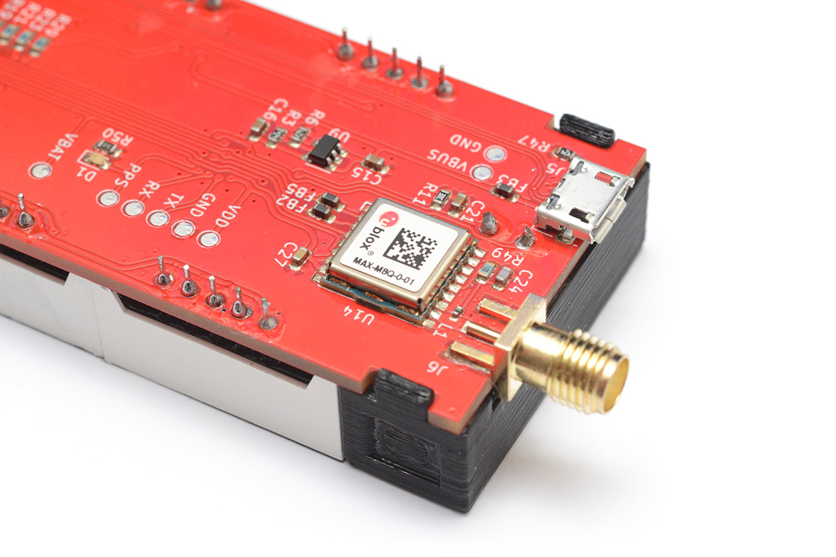
- the "time" side, has the USB port, GPS module and battery holder
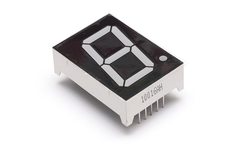
Nineteen 1-inch common cathode 7-segment displays:
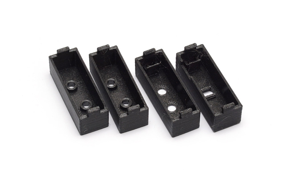
Four 3D printed parts:
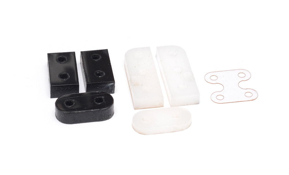
Seven laser cut parts – three in black 6mm delrin, two in white 5mm delrin, one in white 3mm delrin, and one in acetate film:
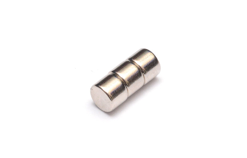
Three magnets (3mm thickness, 4mm dia):
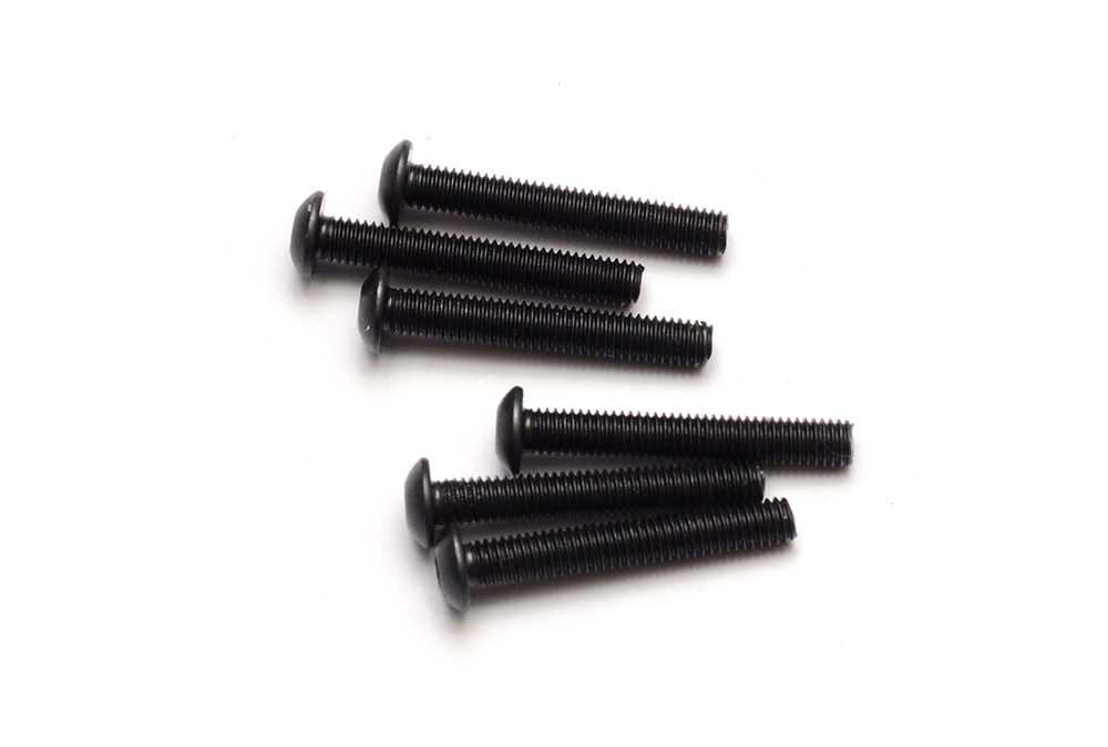
Six M3 x 20mm button-head bolts:
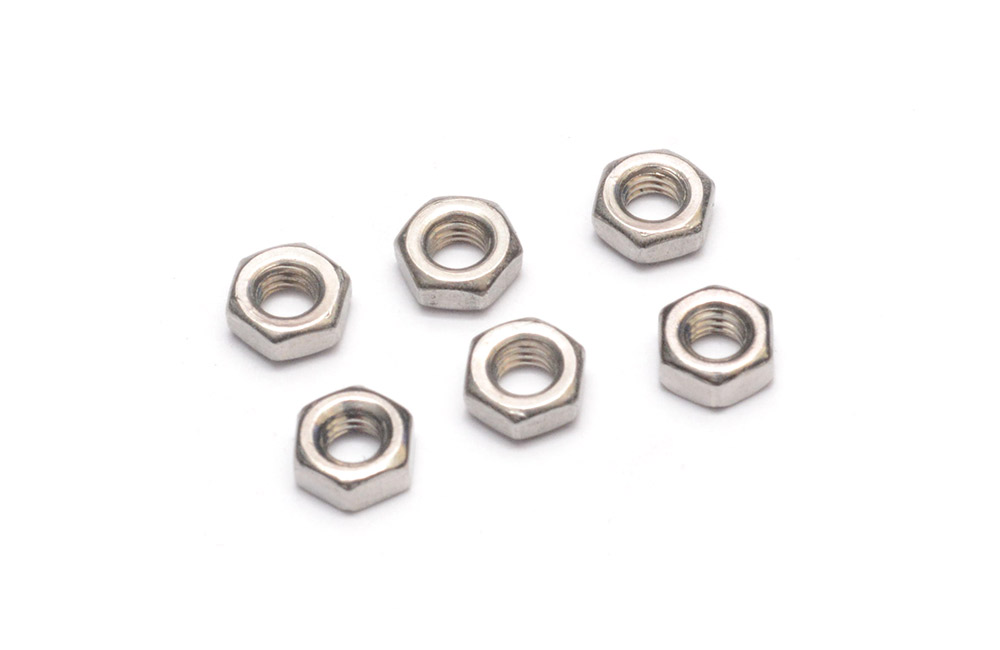
Six M3 nuts:
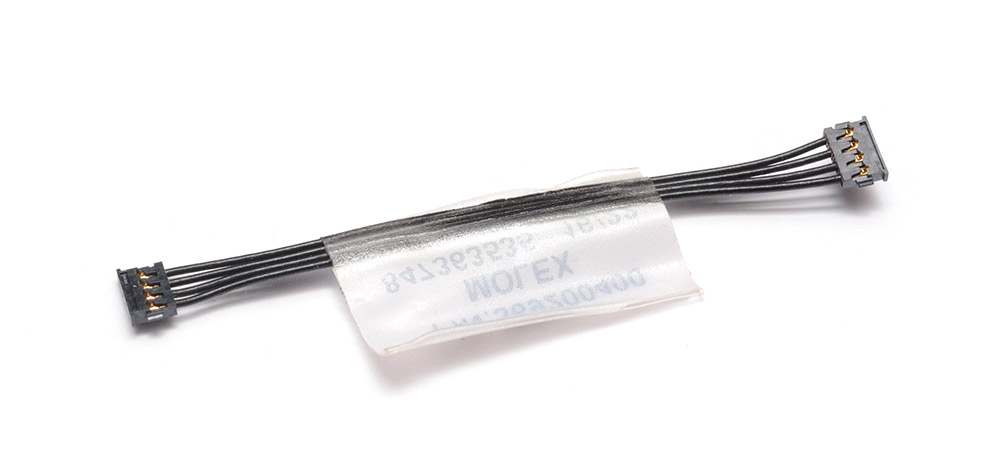
One board-to-board cable (Molex 0369200400):
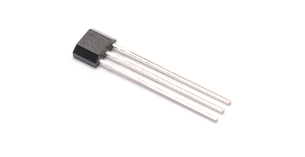
One Hall effect sensor (either TSH253CT B0G or DRV5032FCLPGM):
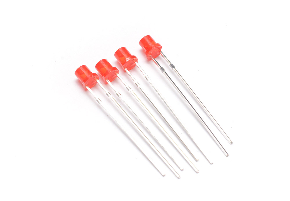
Four 3mm flat-top diffused LEDs:
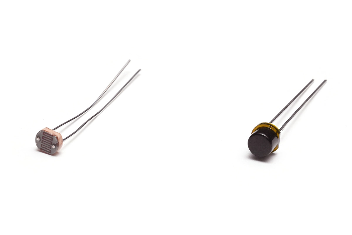
One light sensor – either an LDR (GL5528, left) or phototransistor (VTT9812FH, right):
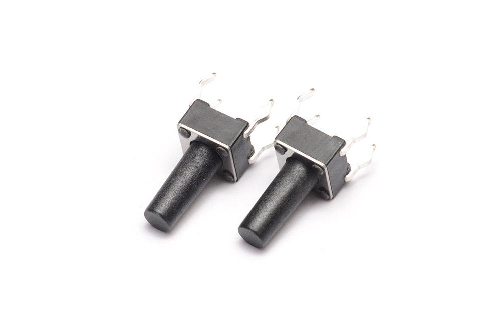
Two 12mm push switches:
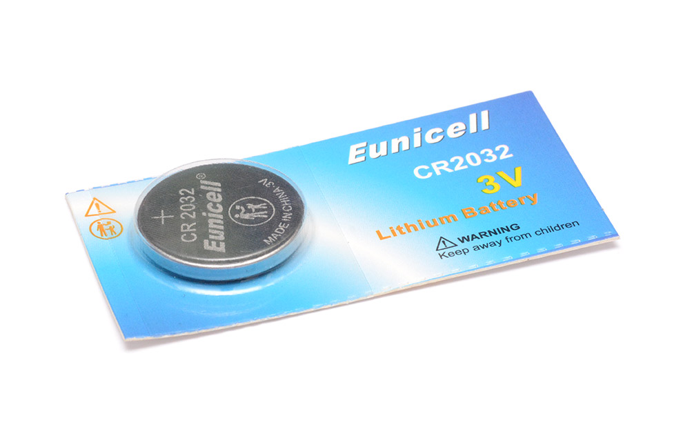
One CR2032 coin cell:
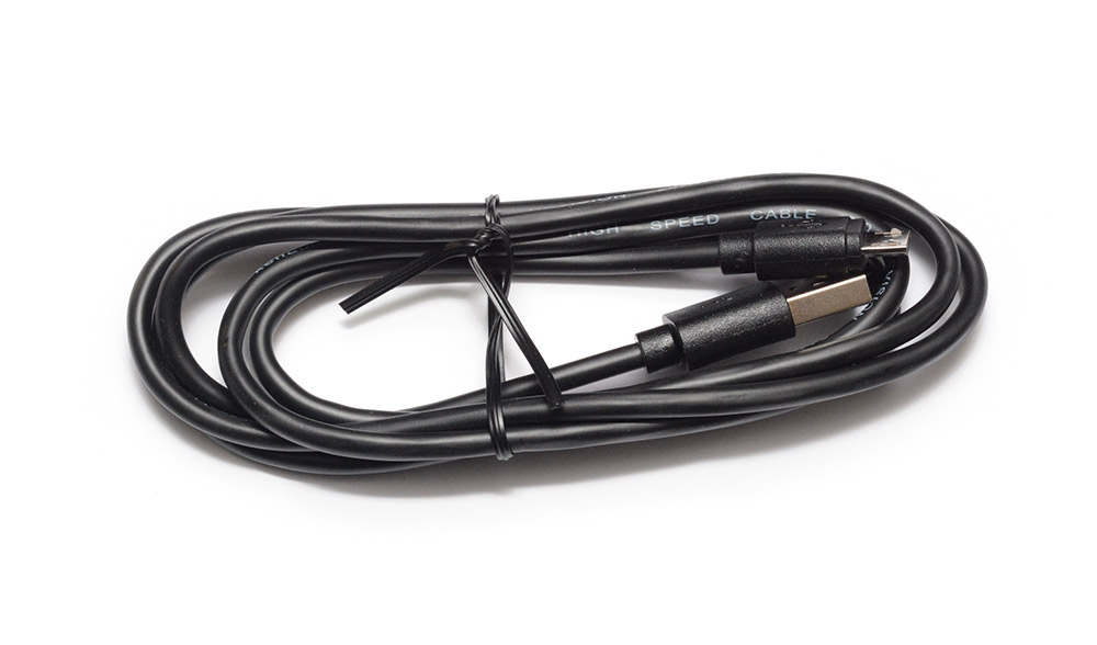
One USB cable (micro-USB or USB-C depending on board version):
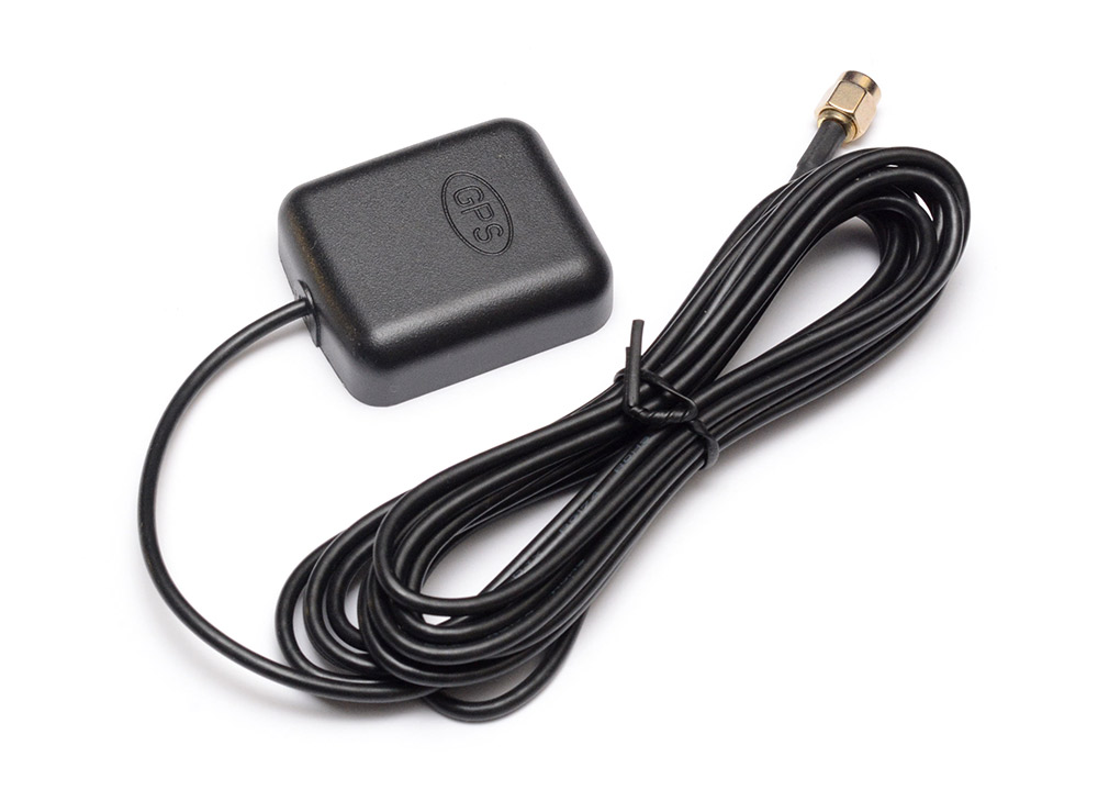
One SMA GPS antenna:
Steps
1. Prepare digits
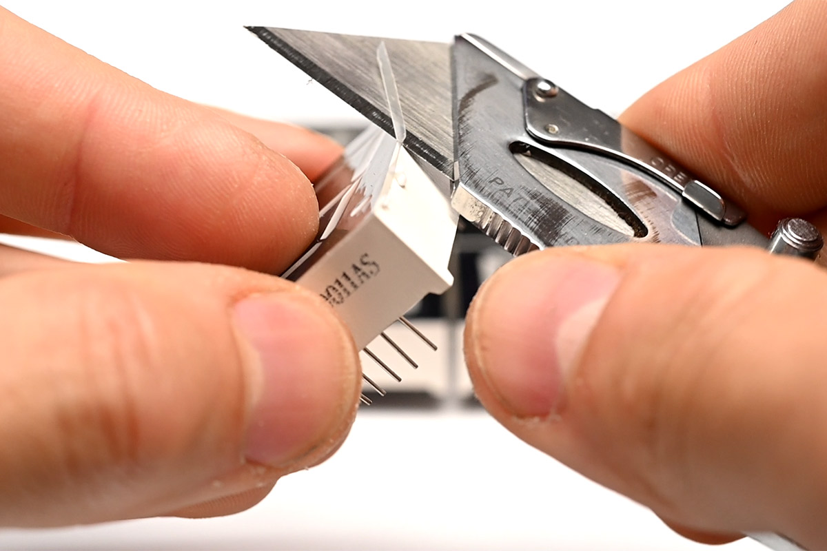
You are welcome to peel off the protective film, however I now think it's best to leave the film in place, particularly if you plan to handle the clock a lot, as it prevents the digits from getting scuffed and scratched. The plastic is white underneath so damage to the black finish can be quite visible.
However, the film protrudes over the edge of the digits and looks messy, so I run a sharp knife along each edge to clean it up.
Give each digit a visual inspection. Very rarely, there are manufacturing problems that should be obvious from looking at the back of the digit. I made an effort to spot these while preparing the kits, but if you think there's a problem send me an email and I'll post some more to you.
While you have the knife out, it's worth cleaning up the 3D printed parts too if they need it. Any stringy bits of plastic near the tabs can interfere with them, in the worst case leading to them snapping when you come to fit them.
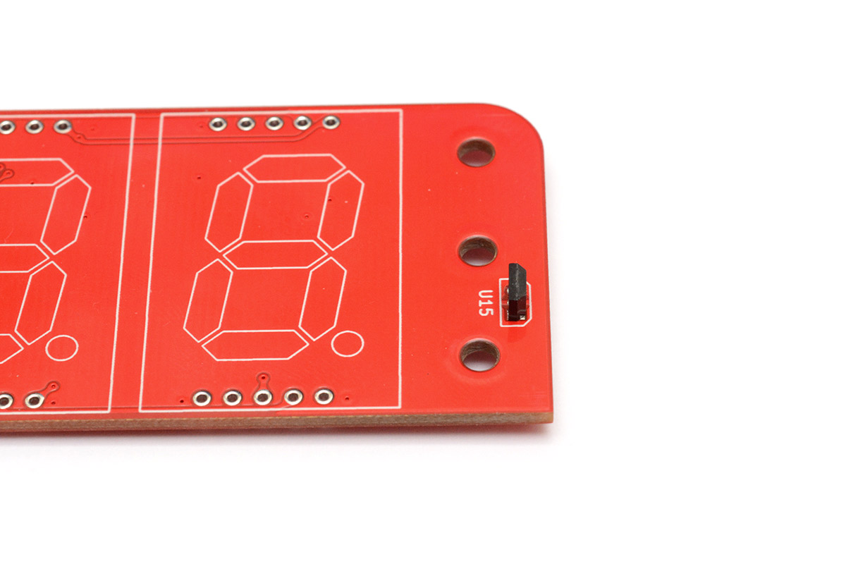
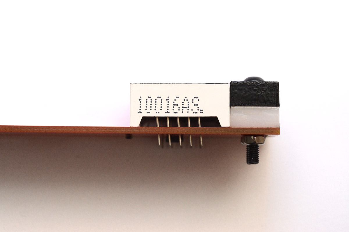
2. Hall effect sensor
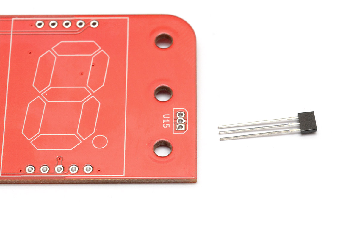
The hall sensor is the most difficult part to solder because the legs are very close together. It needs to be fitted to the date side of the clock, with the outline matching the white silkscreen labelled U15. If you fit it backwards, it won't work.
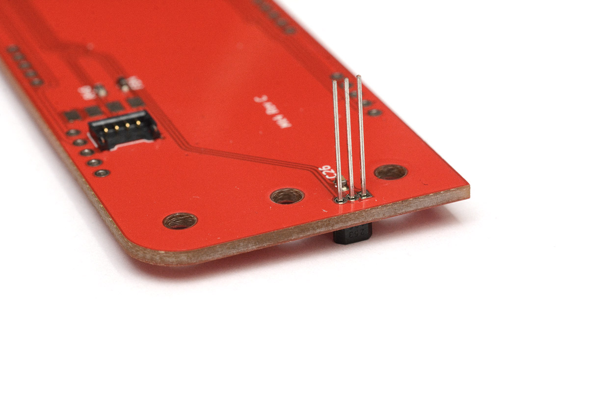
For revision D of the PCB, I slightly widened the footprint for the hall sensor. This makes it easier to solder, but the splayed legs mean it can't sit flush on the PCB. Gently push it down as far as it will go. You can offer up one of the 5mm white delrin pieces to check the height:
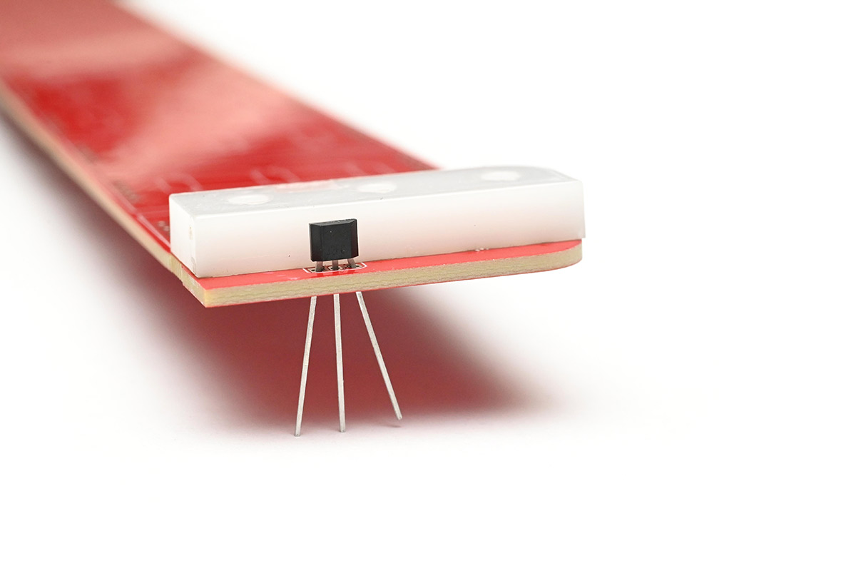
Place the board flat on the desk and then solder the three legs. If solder bridges between the legs, you'll need to use solder wick or a solder-sucker to fix it. Once soldered, trim the legs short.
The rest of the parts have more space between the pins, so should be easier.
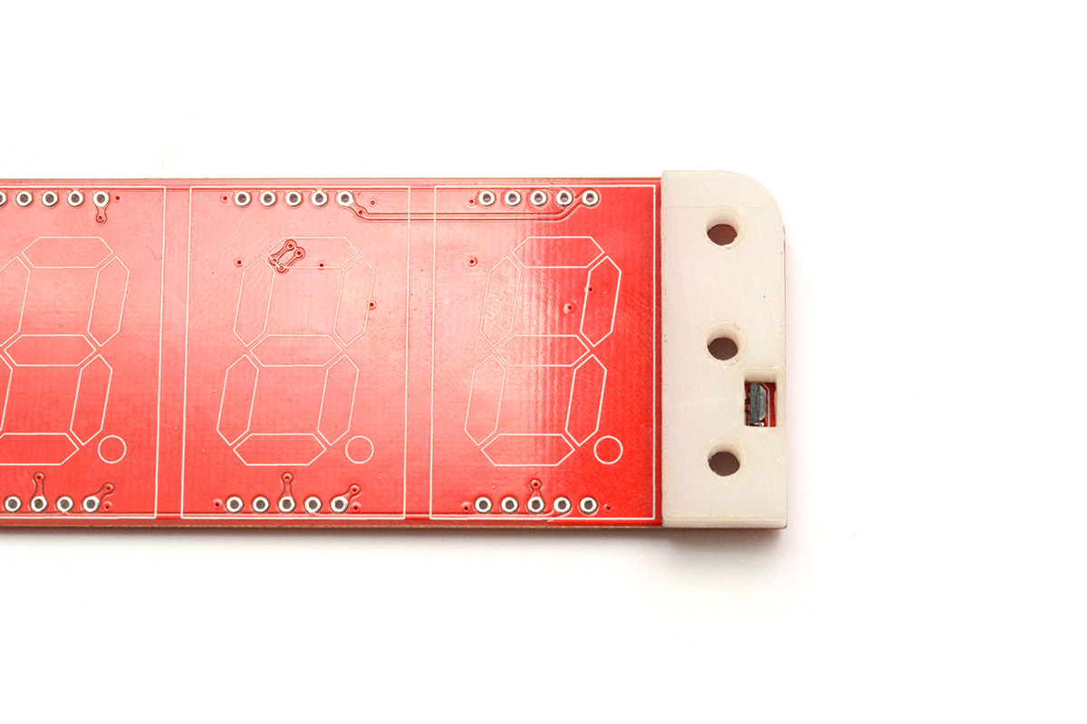
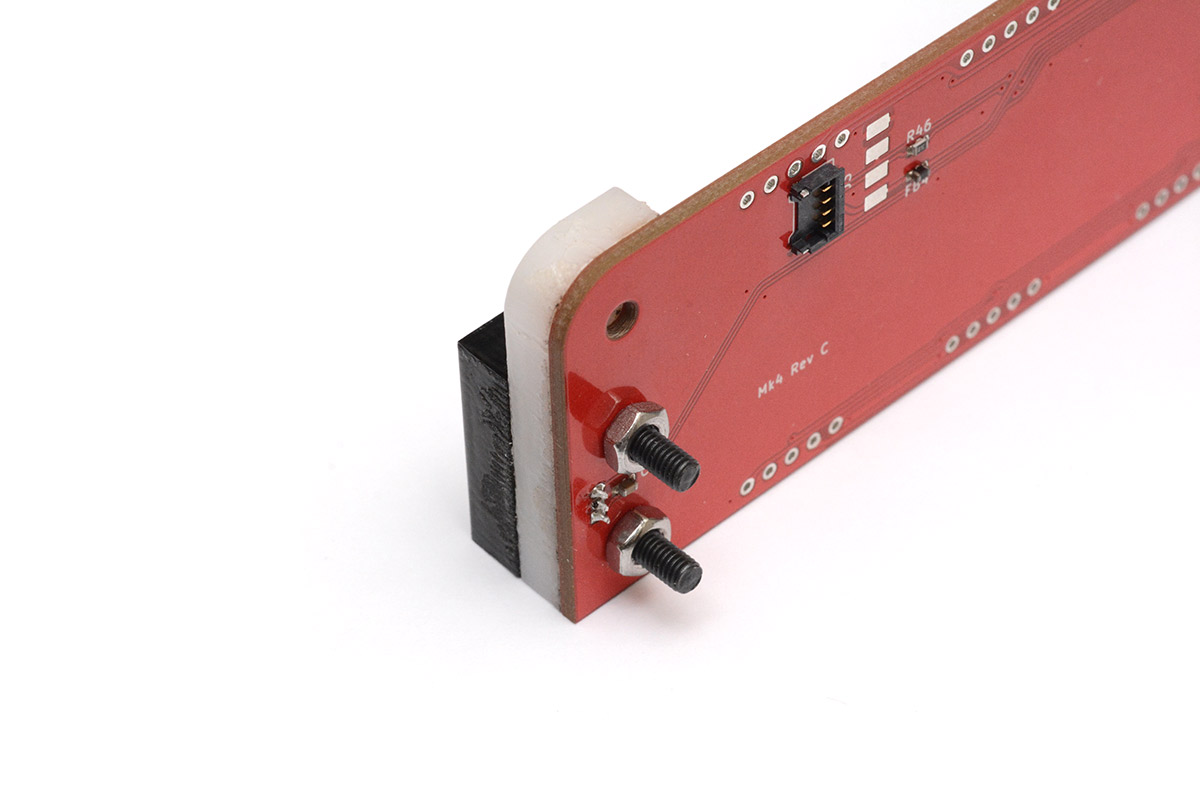
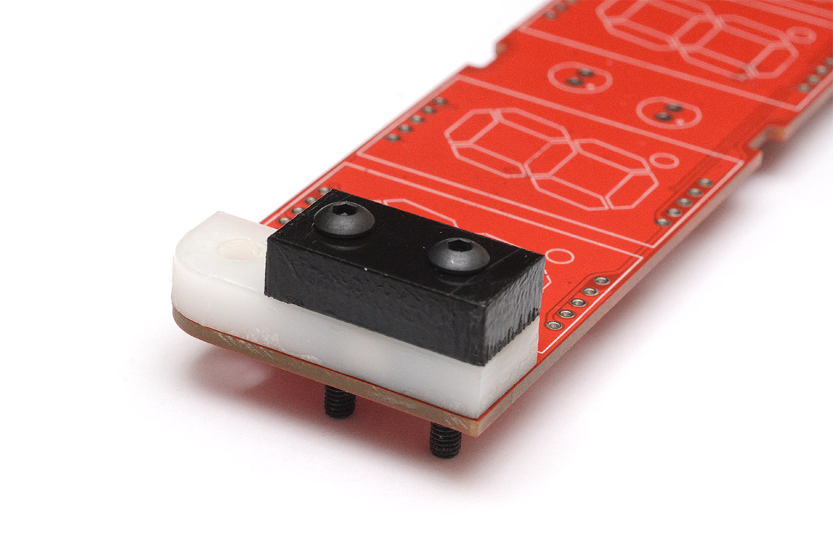
3. Hinge support pieces
Place the 5mm-thick white delrin part over the hall sensor. The "dirty" side should face the board, and the curved edge should match the board outline.
There may be paper tape covering the top surface of some laser-cut parts, which helps protect them from residue while they were being cut. That should be peeled off.
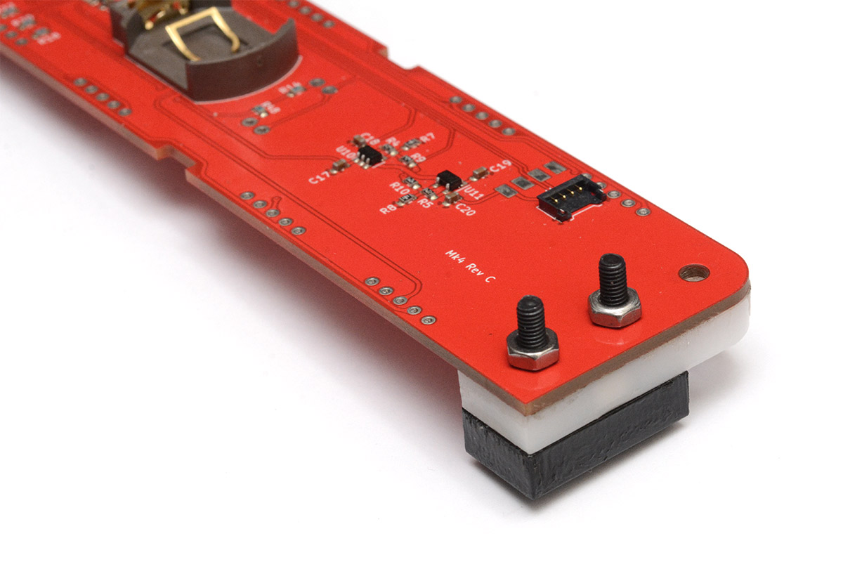
Place a rectangular black 6mm delrin part on top, and fit it together using two M3 bolts. Note the black rectangles are not rotationally symmetrical, make sure the bottom of the plastic parts line up. If it doesn't, rotate the black rectangle 180 degrees.
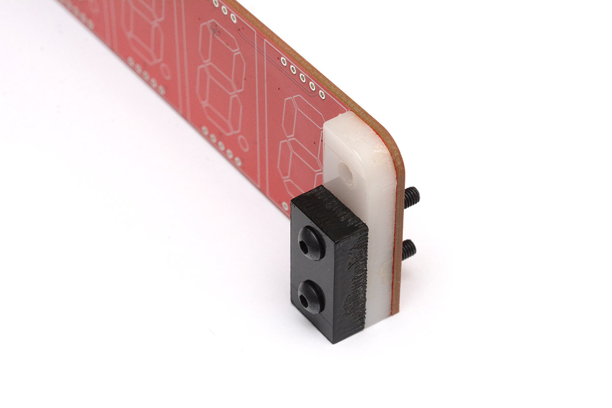
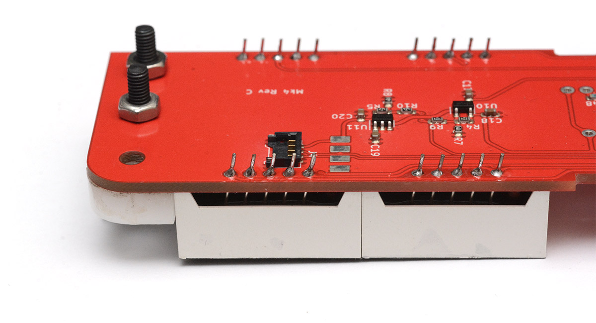
You can then secure this to the board using M3 nuts. Screw the nut on most of the way by hand, then hold it tight with pliers or a wrench while tightening the bolt with a 2.0mm hex key. It doesn't need to be super tight, just secure.
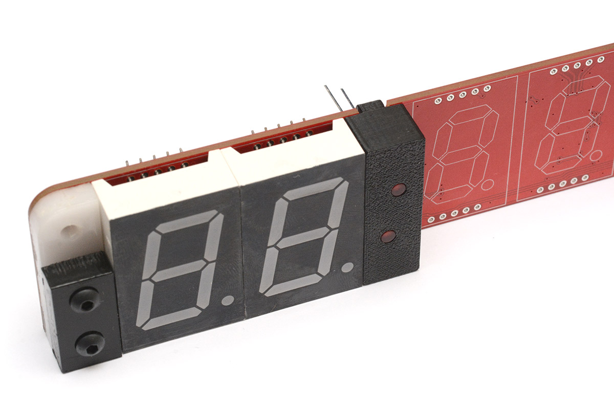
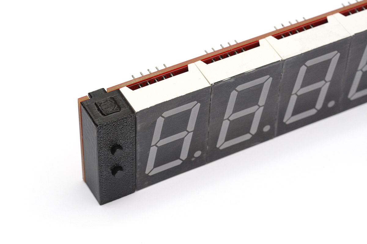
4. Fit first digit
When fitting the digits, always make sure that the decimal point aligns with the markings on the board. Don't fit the digits upside down!
It's essential that the digits next to the hinge are flush with it. Different suppliers of 7-segment displays put the pins in slightly different places, so you may need to bend the legs to get it to line up.
You want the digit to be flush to the plastic, and the plastic to be aligned to the board edge. If there's a gap between the digit and the plastic, try to shift the digit closer, as the gap will result in slop in the hinge when the clock is finished.
Once soldered down, it becomes much harder to adjust this, so give everything a wiggle and make sure you are happy with it.
You can then solder the first digit in place. Be extremely careful not to touch the wire-to-board connector with your soldering iron. The plastic will melt and ruin it.
It may help to put the board on the edge of a desk, or some scrap material, to get the digit flush to the board with the bolt heads present. It may also help to support the other end of the board with a spare digit.
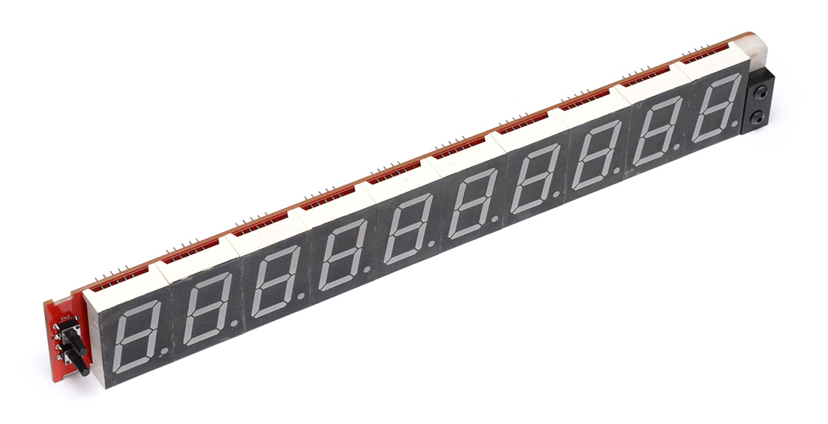
5. Fit rest of the digits to the date side
Fit and solder the rest of the digits, adjusting the legs as necessary. Make sure they are flush to the board when you solder them. A spare piece of plywood or cardboard on the desk can be useful, with the bolt heads hanging off the end.
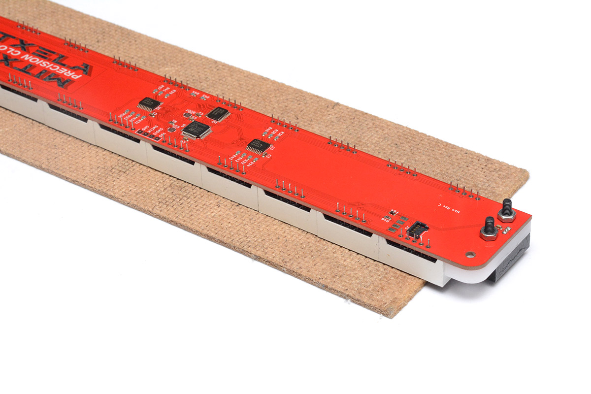
Or you could even use the polystyrene foam that the digits were shipped with.
A nice technique is to first solder just one or two legs for each digit, then wiggle the digits into position so they are all aligned, then solder the remaining pins.
Once again remember to check that the digits are the right way up, the decimal point needs to align with the white outlines on the board.
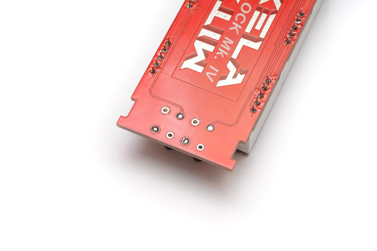
6. Fit push switches
Before soldering the switches, notice that their legs stick out the back, which means that if you press the switch with thumb and forefinger, it would be uncomfortable.
One option is to simply fold them flat, or you could potentially trim or file down the legs after soldering, but I find it's best to trim the legs of the switches before soldering.
This does make it harder to solder them, as they no longer snap into place, so go with whichever you feel comfortable with. The ground pins will need a lot of heat to melt the solder.
You only need to solder the signal wire (with the track visible) and one of the ground pins for each switch. If it looks like this, you're golden:
For revision D of the PCB, I added extra thermal relief so it should be easy enough to solder all the pins. If your solder is the type that leaves a sticky residue, this is a good time to wipe it off from these joints so it's not sticky when you press the buttons.
Don't fit the 3D printed part yet! You can now put the date board to one side and start on the other board.
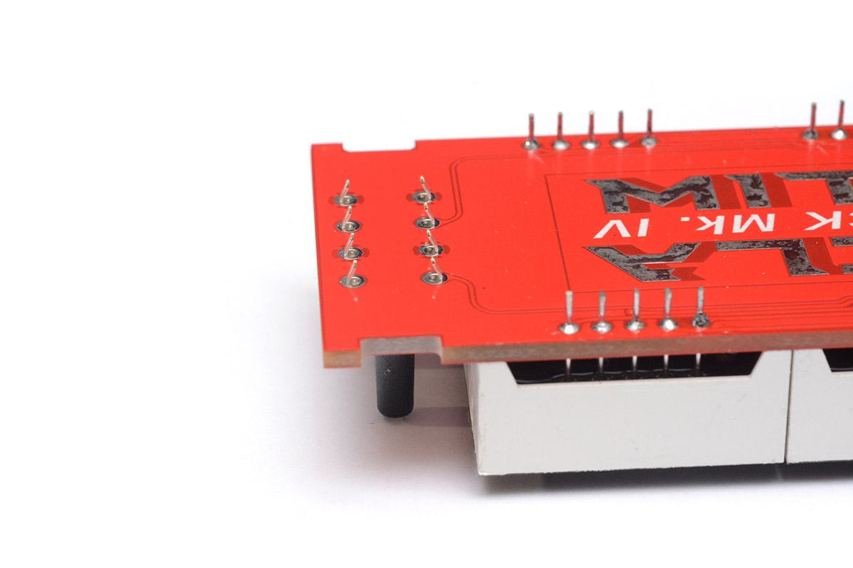
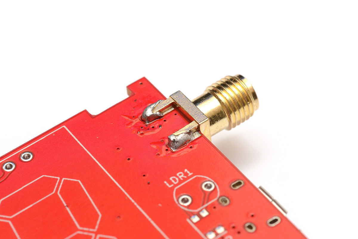
7. (Optional) Solder underside of SMA connector
This step is for revision C only. On newer boards this part has been soldered for you.
Out of the box, the SMA connector is only soldered on the top side of the PCB. While this is perfectly functional from an electrical point of view, you can increase the mechanical strength by soldering the underside.
There is a fair amount of thermal mass to the connector, so it will need a high temperature and some patience.
Once again this step is optional, if you are new to soldering I would recommend skipping this rather than risk damaging the connector.
8. Time hinge
Take the remaining 5mm white delrin part and black 6mm rectangle, and assemble to the board the same as with the other side. This time, instead of a hall sensor, we want to fit one of the small magnets in the gap.
The bolts are magnetic so this can be fiddly. It doesn't matter which way round the magnet goes – the sensor detects absolute field strength.
Again make sure the plastic aligns with the board edge (ensure the black rectangle is the correct rotation) and tighten using pliers and a 2.0mm allen/hex key.
9. Fit the next two digits
Once again, it's important to get this part right or the hinge will not behave correctly. The adjacent digit has to be flush to the plastic. In these pictures, there was a small gap present, so I bent the legs to make sure the digit sits in the right place. I solder just two pins of each digit first, and make sure everything feels right, then solder the rest. Be very careful soldering around the wire-to-board connector.
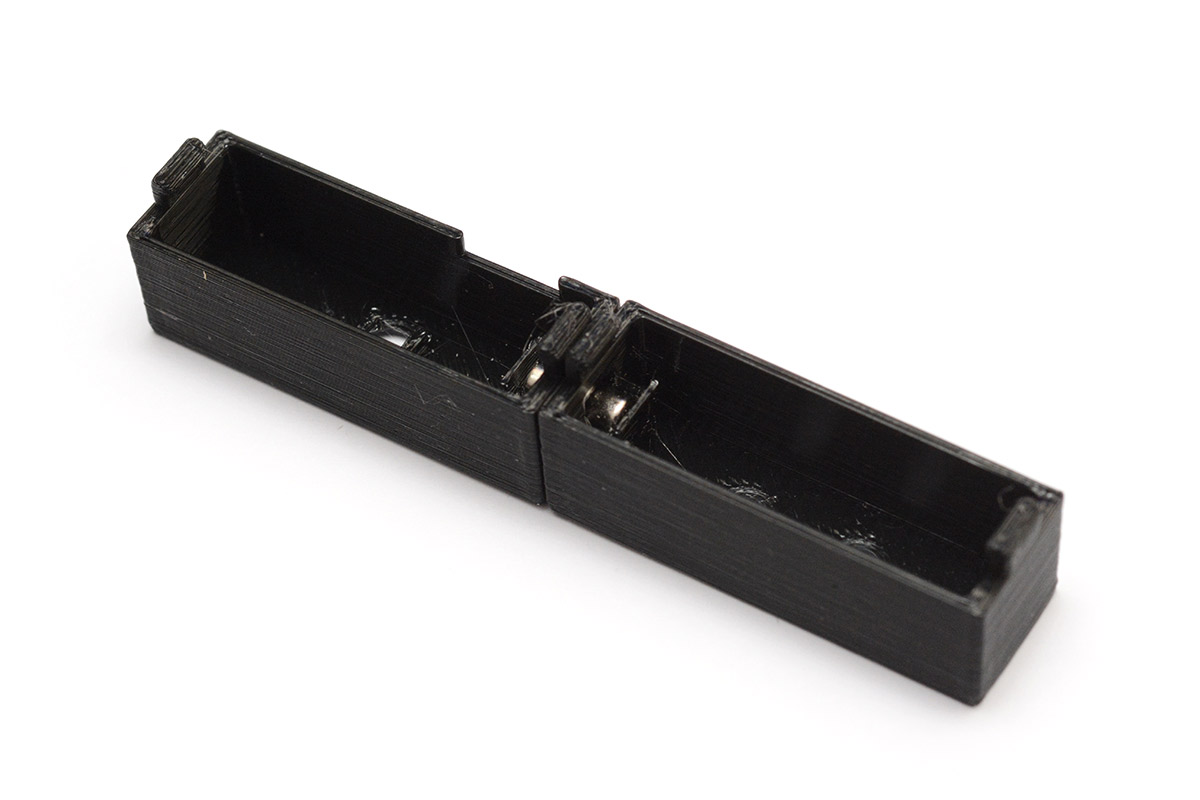
10. Fit colons
There are two 3D printed colon holders. The 3D printed switch cover looks similar but the holes are slightly larger and not staggered vertically. I've now added cutouts to the sides to make it more obvious these parts go between the digits, not on the ends.
Push the 3mm LEDs into them with the legs in the same orientation to match the board. The 3D-printed part is rotationally symmetrical. The LEDs should be a push fit, it sometimes helps to use a screwdriver or tweezers to seat them fully.
The LEDs have a polarity: long leg is +. Make sure they will mount the correct way.
With the LED legs threaded through the board, push the printed part's tabs over the board so it snaps into place. The 3D printed plastic is delicate and can break if you are careless here. Hook one tab over first, then gently push the other one into place.
Don't force it, if it won't snap into place, you can trim the plastic tabs with a knife.
There is intentionally some horizontal play in the tabs so you can slide it up to the digits. When you are happy, solder the LEDs in place and trim the legs short.
11. Fit the rest of the digits and colons
From here you can fit the remaining digits and colons in the same manner as before. The positions are not nearly as important. I'm a perfectionist so I tend to align everything as well as possible, but it's only the digits next to the hinge that really matter.
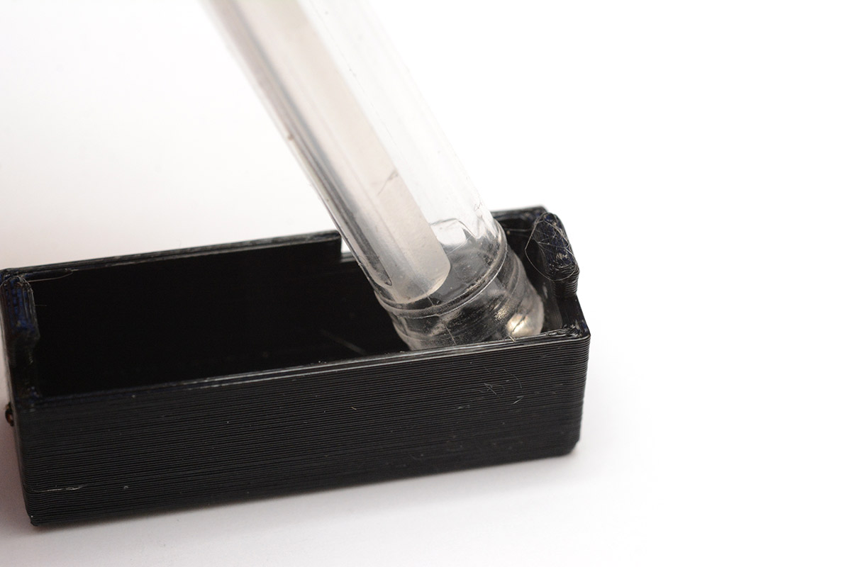
12. Fit magnets
Fitting magnets into the remaining 3D printed parts will help keep the clock together in the folded position. If you don't care about that you can skip this step.
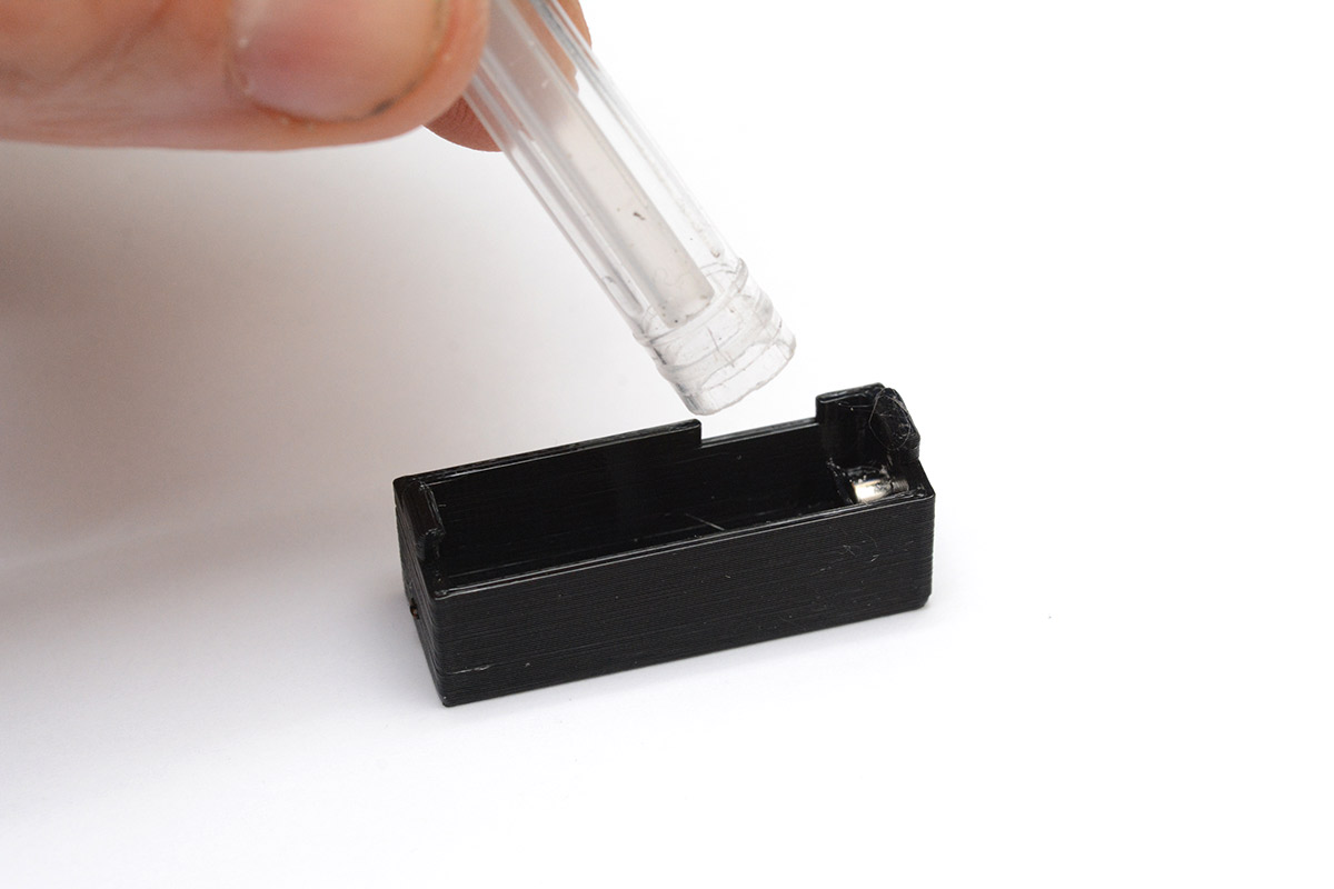
Start by placing one magnet into a receptacle as shown in the picture.
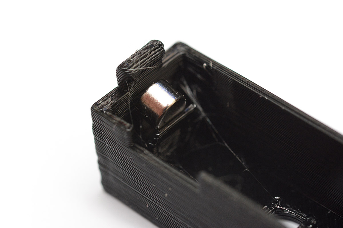
It then needs to be pushed downwards, at a slight angle, to snap into the correct place.
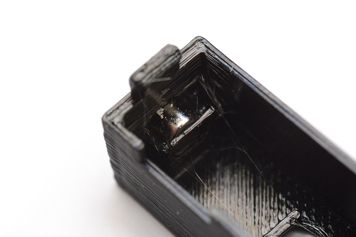
If you're dextrous you can do this with your fingers, but a plastic implement will make it much easier. Something stiff but non-magnetic. Any attempts to use metal pliers will lead to frustration.
A good tool I have found to do this is the back of a ballpoint pen, with the little cap pulled out.
You can tell when it's seated correctly by placing the other magnet on the outside, it should be centred in the rectangle.
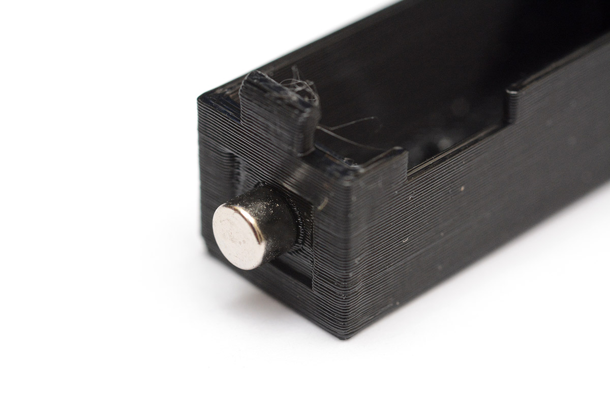
For the second part, you need to make sure the magnet's orientation is correct, otherwise they will repel one another. I start by placing the two parts together, then letting the magnet find its attractive orientation.
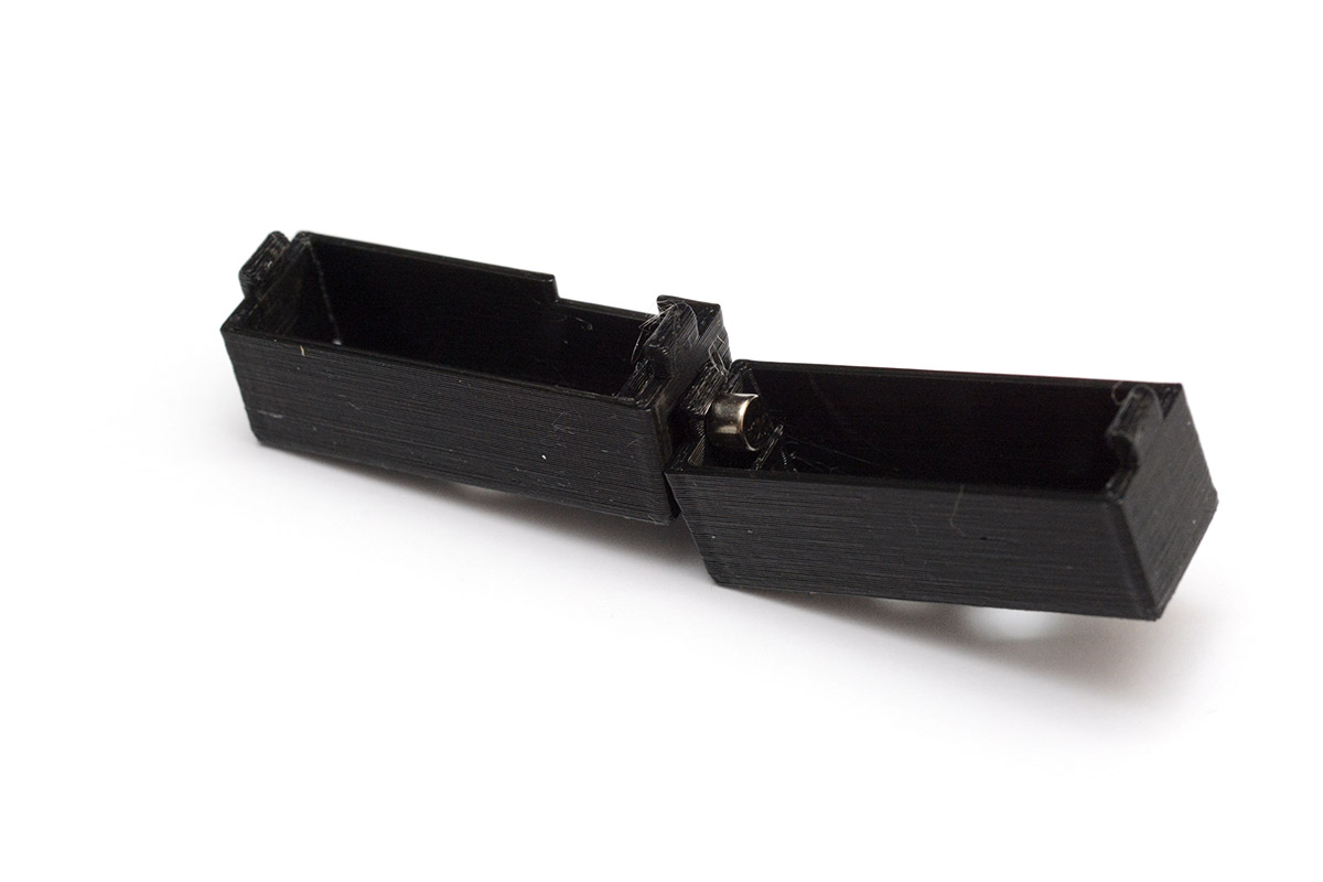
From here, again pressing with the back of a ballpoint pen should seat the magnet correctly.
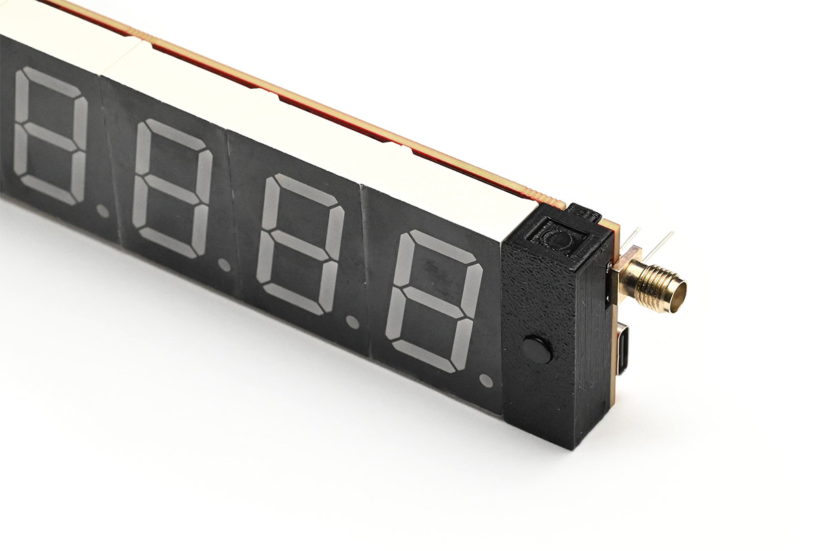
13. Fit switch cover
You can now fit the switch cover. Make sure the magnetic end is facing up, relative to the digits, so that it aligns correctly when the clock folds. You may need to use tweezers or pliers to wiggle the switches through the holes. It should snap into place easily, without excess force.
Once fitted, the buttons should press freely. If they're rubbing or jammed against the plastic, you'll need to wiggle things around. In the worst case you may need to remove the plastic part, and either re-solder the switches, or make the holes a tiny bit bigger with a drill bit.
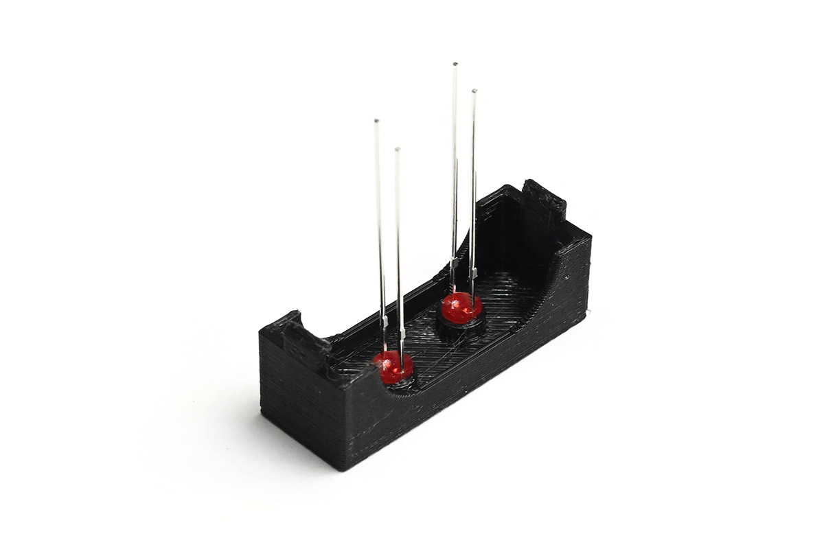
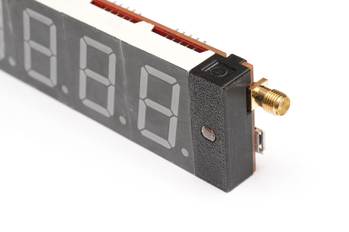
14. Fit light sensor
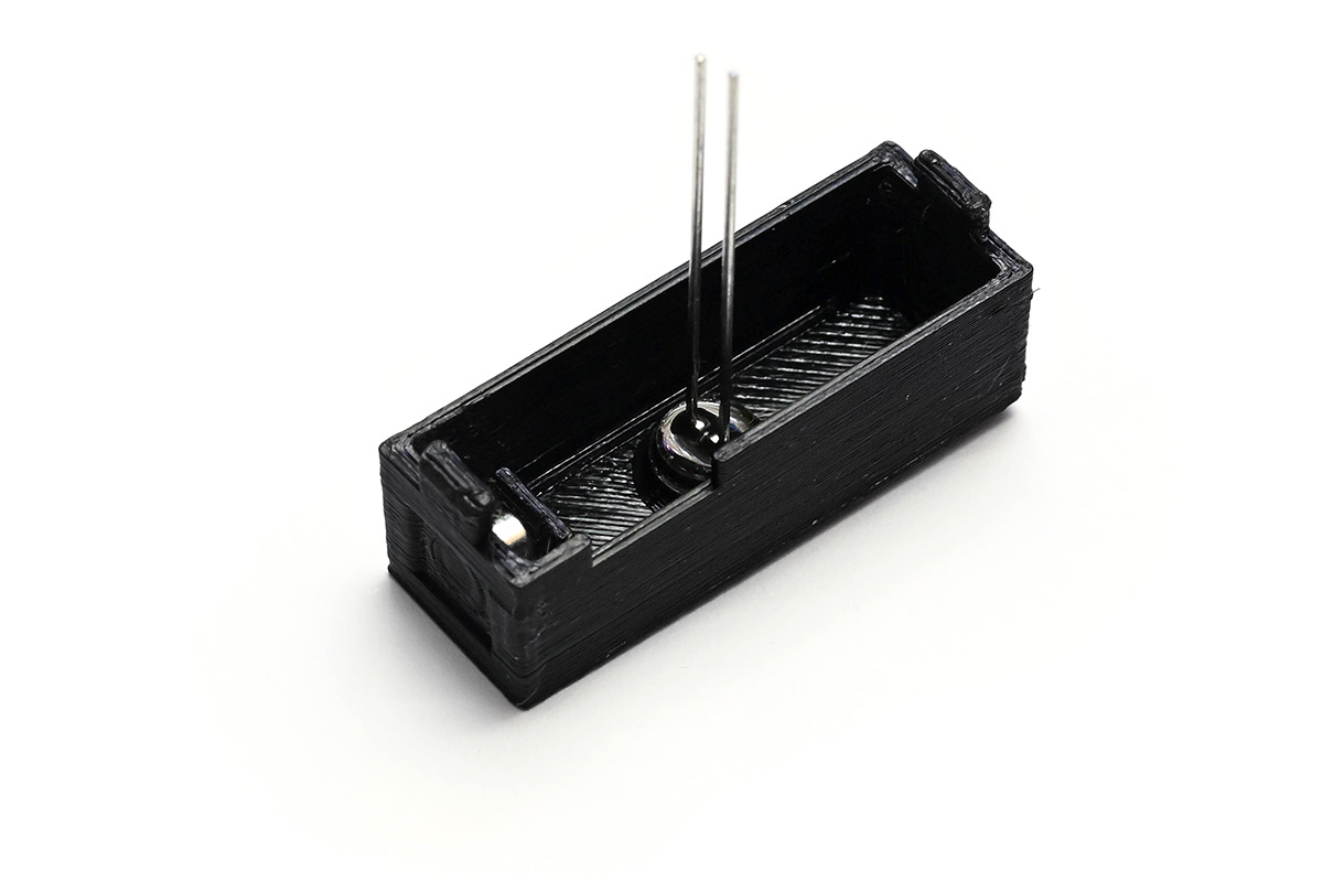
The light sensor goes within the last 3D printed part.
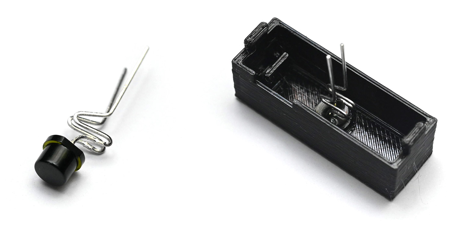
A reminder: the light sensor will either be an LDR, or a phototransistor, depending on the version of the kit.
If your kit came with an LDR, it needs to be pushed flush. There is a varying amount of varnish on these parts, if it doesn't fit perfectly don't worry. As you solder it, the warmth will slightly deform the plastic to a perfect fit.
The LDR has no polarity and can be fitted either way. The 3D printed part needs the magnetic side to point upwards.
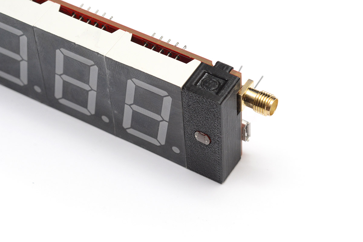
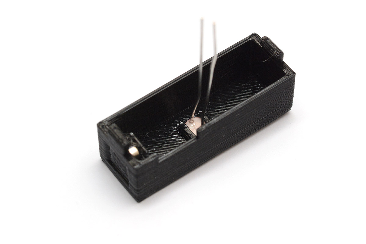
If your kit has the phototransistor, then it's just the same as fitting the LEDs. It has a polarity: long leg is +. Check that the legs of the phototransistor will line up correctly when it's fitted, the magnet needs to point up, and the little cutout sits over the antenna connector.
Be very careful not to touch the other components as you solder these last joints.
For the LDR, you can push the clock flat on the desk as you solder, to help keep it flush to the face.
For the phototransistor it's best to let it stick out of the front slightly.
Finally, trim the legs.
15. Prepare cable
The Pico EZ-mate cable comes with a label that needs to be removed. Unpeel it or cut it away, then clean the wires of any sticky residue (isopropyl alcohol works well).
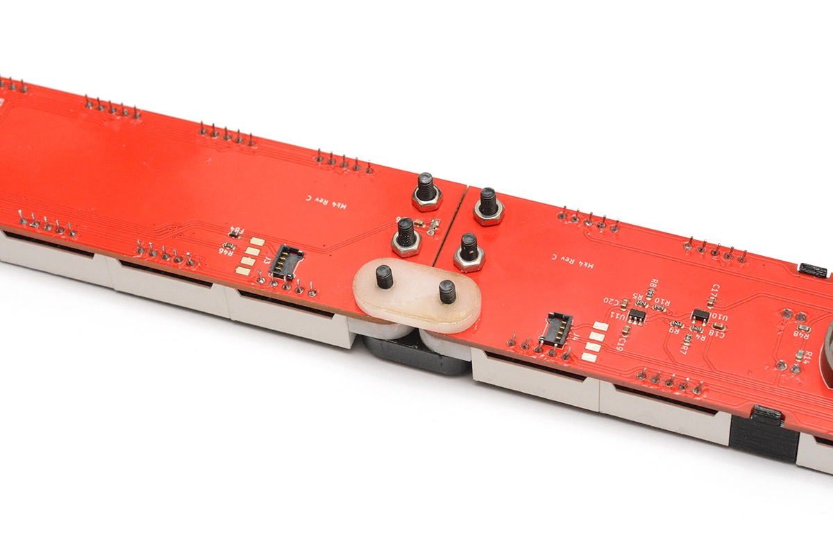
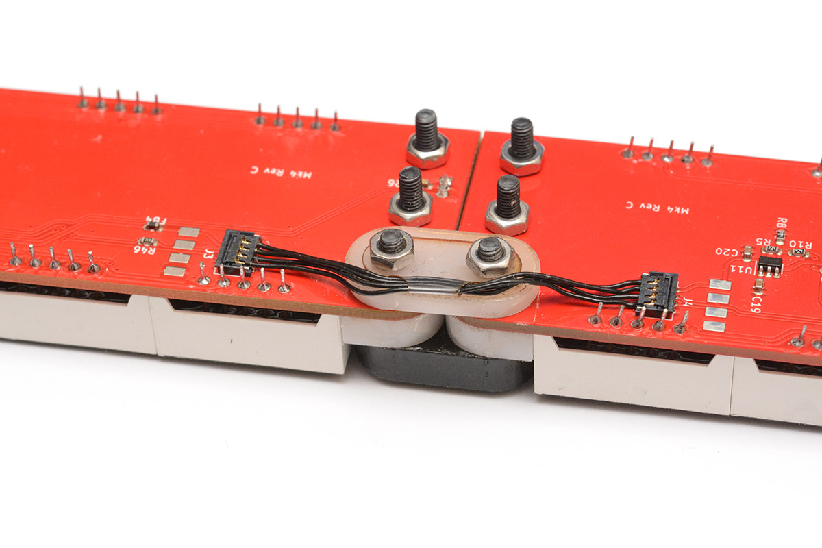
16. Construct hinge
The holes in the remaining white part are slightly undersize, and the bolts should form threads into them as they are tightened. The "clean" side of the white piece should face the circuit board, so that the kerf of the laser cutter, which is slightly conical, makes it easier for the threads to bite.
Start by pushing the two bolts through the black delrin piece, then through the two halves of the clock, and then a bit at a time, alternately tighten them into the white delrin.
You need to tighten these bolts all the way, then back off very slightly. The idea is to set the hinge tension with the bolts, then use the last nuts to lock the tension in place.
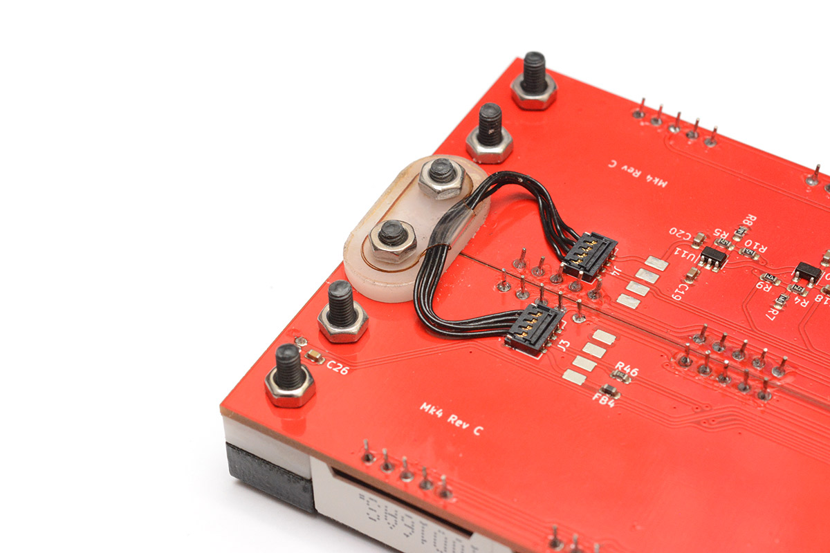
Before fitting the lock nuts, you also need to fit the cable and its holder, the laser-cut piece of acetate. To connect the cable, you place each end over the socket and push towards the PCB.
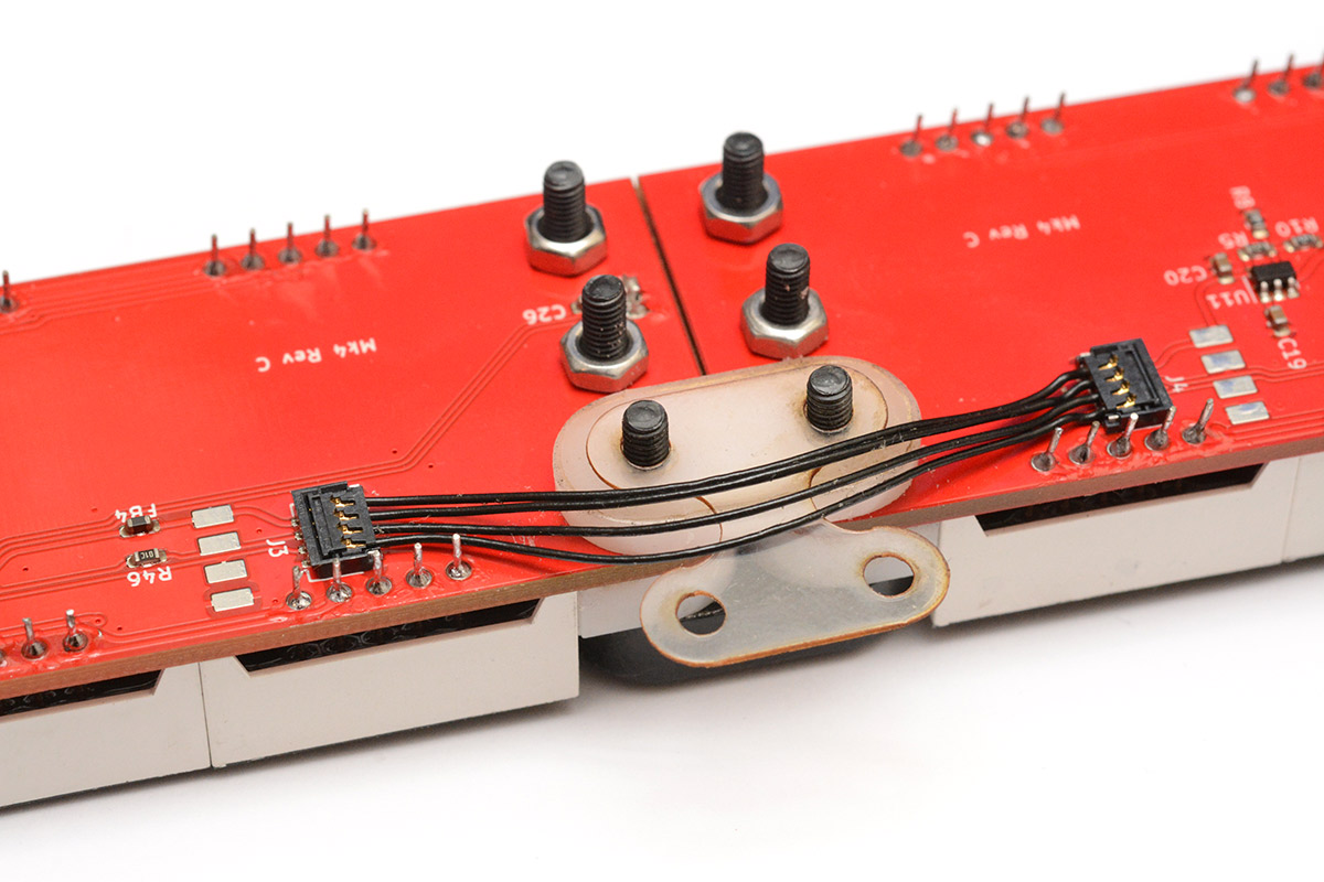
Fold the acetate over, and then very gently tighten the lock nuts, being careful not to trap the cable.
For the first use of the hinge, you will need to guide the cable so that it bends correctly. Do this very slowly and gently so that it learns to bend the correct way.
You can then work the hinge back and forth a few times, and when you're happy with it you can give the nuts a final tighten.
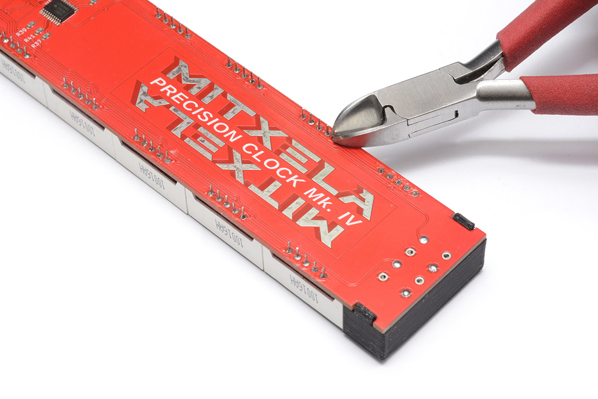
17. Trim legs of digits
Totally optional, but the clock is much nicer to handle if the legs of the digits are trimmed flush. Just be careful around the hinge area not to damage the wire-to-board connectors.
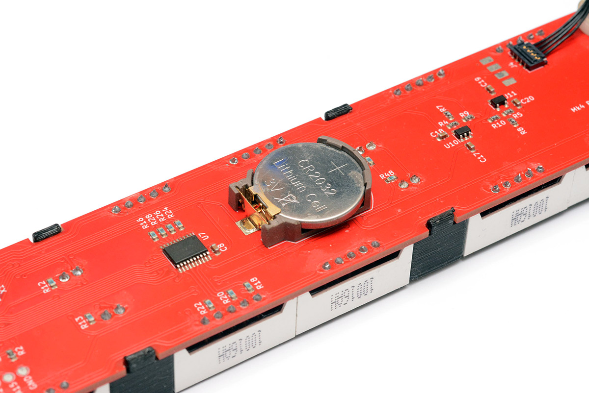
18. Power on
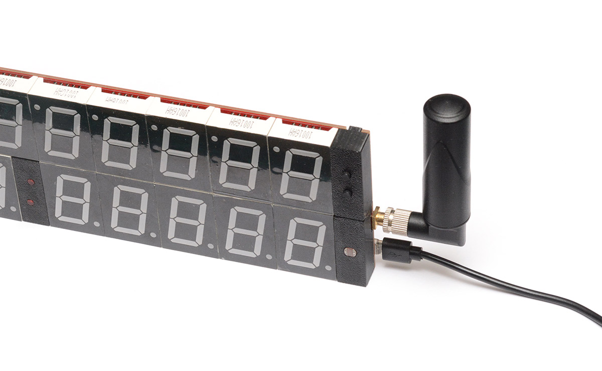
Fit the coin cell into the holder, connect the antenna, plug in the USB cable and see if it works.
On very first power-up, you may see a loading animation while it flashes the firmware image.
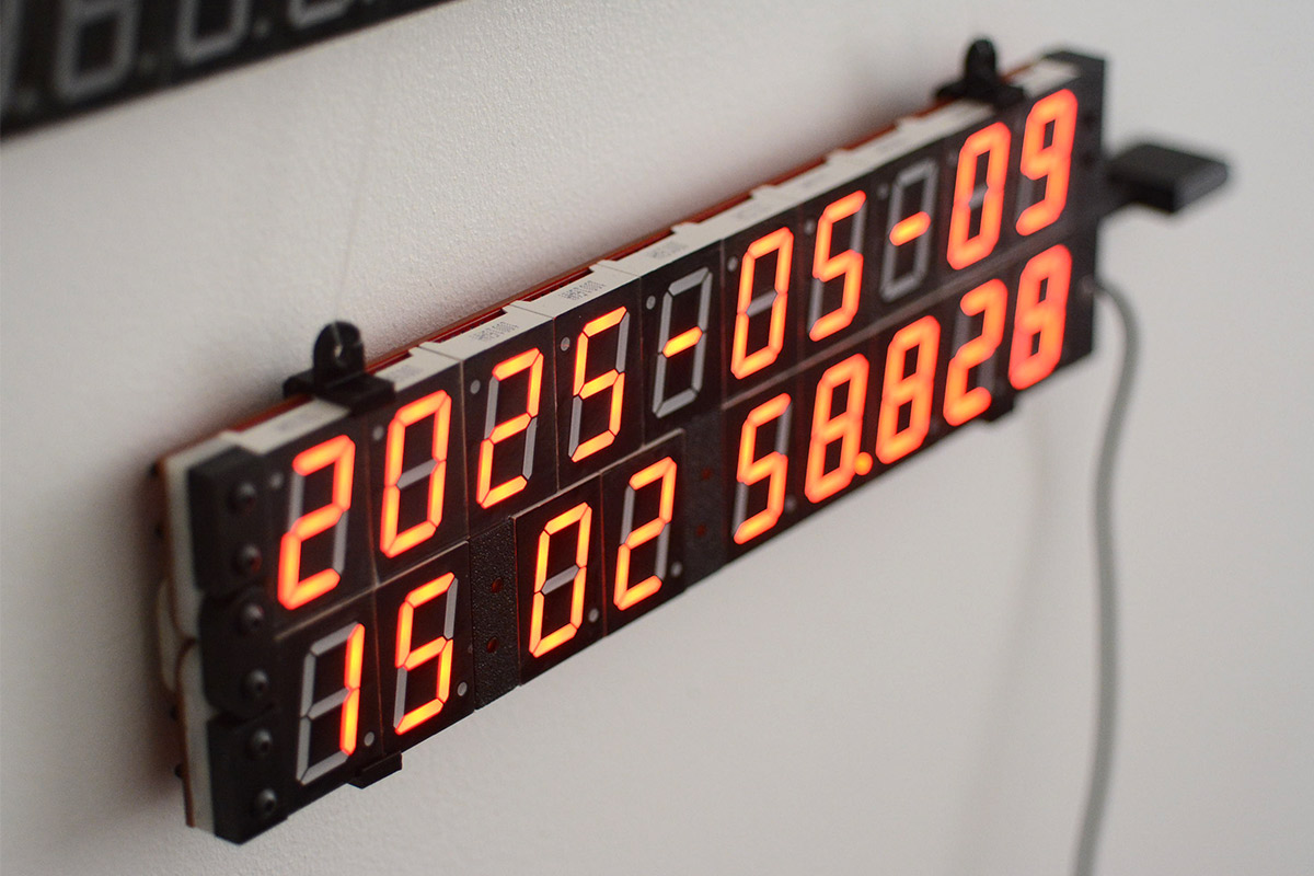
It should then show a placeholder time and date (2000-01-01) while it searches for GPS signal. After finding one satellite, it should update to the approximate UTC time.
Once it gets a full GPS fix, it should update to local time with full precision. With the coin-cell backup, future power-on should be faster.
Check the buttons work, they should cycle back and forth through the modes. Check the date display inverts when the clock is folded in half.
All done! You may want to check if there are any firmware or database updates for the clock, and perhaps check out the documentation to play with specific modes and features.
Troubleshooting
I will fill out this section with common problems as they become apparent. In the mean time send me an email or post on the forum.One of the most common assembly problems has been fitting a digit upside-down. I've written a tutorial here on how to unsolder a digit without special equipment.
3D printed parts: don't stress if they break, the tabs are only meant as a convenience but it's fine to just use glue. In the worst case you could 3D print the parts again, the STL files are in the cad folder of the clock4 repo.
d2 Error is shown when the date side of the clock is not responding. This could be a problem with the hinge connection, or a short somewhere on the date side. Check the soldering on the hall effect sensor, if possible check the continuity between each pin to check they're not shorted. You can also check continuity of the hinge by using the test pads next to the connectors.
For a full list of possible error codes see the documentation.
Antennas
A variety of GPS antennas can be used with the clock. The SMA connector provides a 3.3V bias voltage to power an active antenna.
The widely available "puck" antennas on a 3 metre cable work fine. You can also use an SMA extension cable (usually RG174, but anything 50ohm will work) to position the antenna further away. There will be some losses in the cable, but that's usually worth it for the benefit of a better antenna position. The delay to the timepulse is negligible, it's around 5 nanoseconds for every metre of cable.
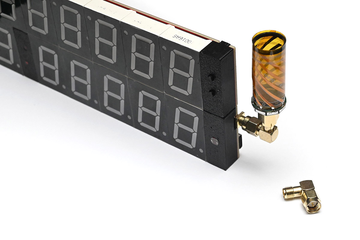
There's a large number of alternate antennas available and most, if not all, should be supported. For portability, you can get a reasonably small helical stubby GPS antenna. These are still quite large for what I would consider a stubby antenna, but they work well, and unlike the patch antennas should have some resistance to erroneous GPS signals caused by reflections off of buildings.
A lot of the helical antennas have a straight connector instead of a right-angle one. You can get a small right-angle SMA adapter which will allow those to be used with the clock. Here's one without the plastic case, it's interesting to see the construction from a rolled-up flex PCB:
I also prepared some tiny antennas by taking an active patch antenna and crimping an SMA connector as close as possible to it. Even with the correct stripping and crimping tools, the SMA connectors are a pain to fit, so bear that in mind if you want to attempt it.
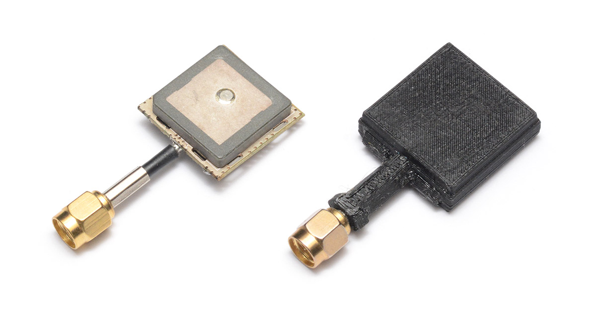
The 3D printed case is very thin and has no effect on the signal. The design files for it are here.
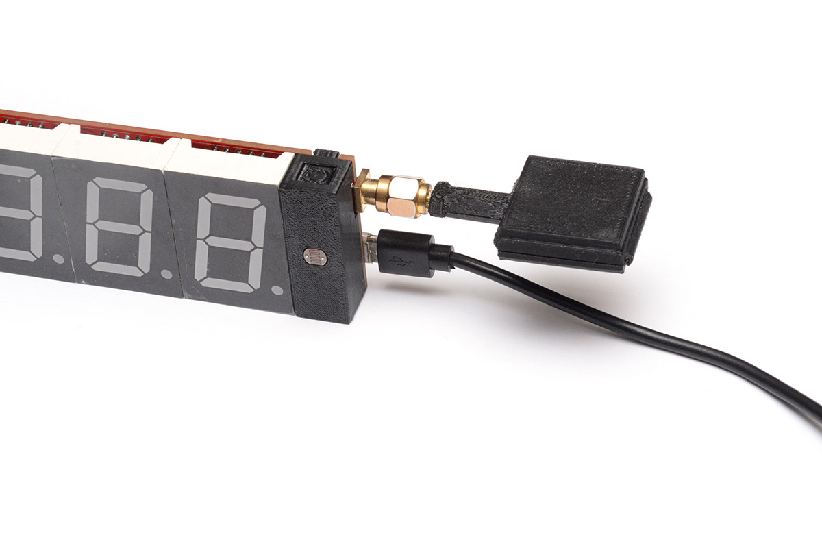
If one were inclined, it's probably possible to fit an even smaller antenna onto an SMA connector.
Some antennas are billed as GPS+GLONASS, whereas others are GPS exclusively. The slightly wider bandwidth for the dual antenna may have a tiny effect on the overall GPS reception, but I haven't tested this. While the GPS module can pick up both, it only derives the time signal from the GPS satellites.
Wall hanging
I frequently describe the clock as a "Wall Clock" to make it clear that its function is a precision display of the time, rather than a reference oscillator. However, actually mounting an unmodified clock on a wall is not something I made provisions for. Mostly because the PCB screw holes on the previous clock were never particularly satisfying in use, and the hinge complicates things.Anyway, here are a few 3D printed options for wall-mounting.
Here's a clip to hold the clock in the folded position. Print on its side. Use some picture wire or string between the clips.
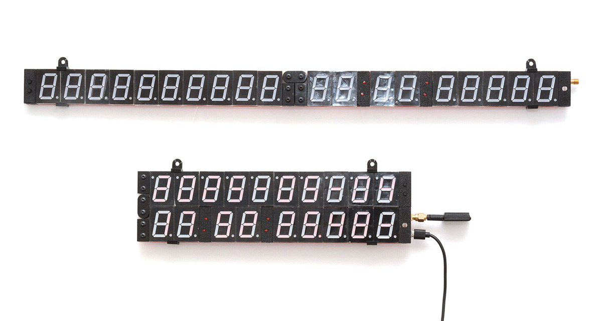
The same idea can be applied to the unfolded clock, with a shorter version of the same clip:
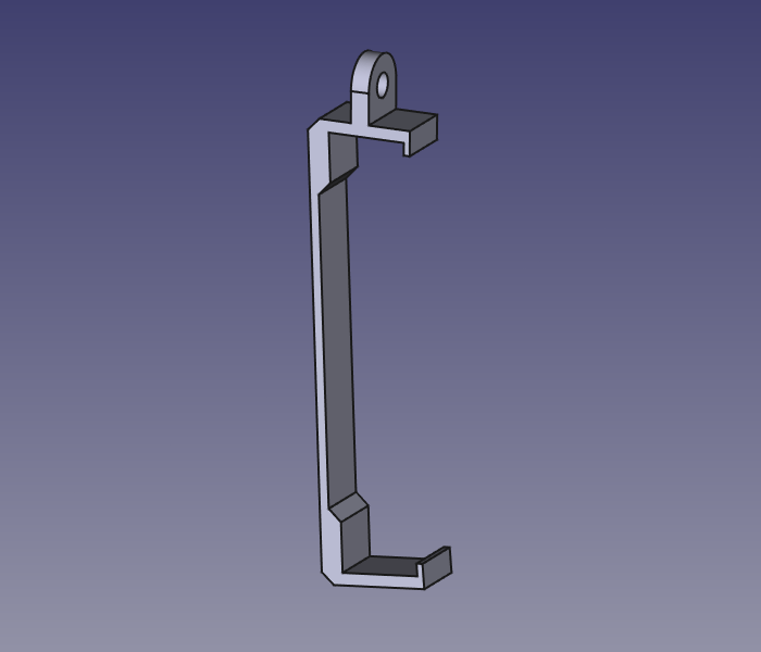
However it also needs something to keep the hinge from folding, if held from the ends like that. One option is to lock the hinge with a part like this:
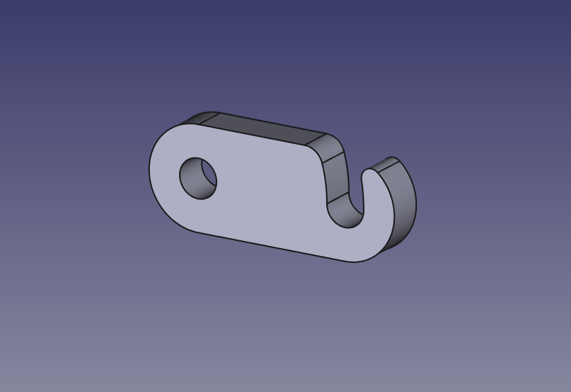
It press-fits over one of the bolts on the back, and allows you to latch the clock open. It can be 3D printed, but with only a few actuations it may start to wear down. I would recommend laser-cutting it in Delrin for maximum strength.
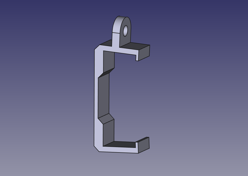
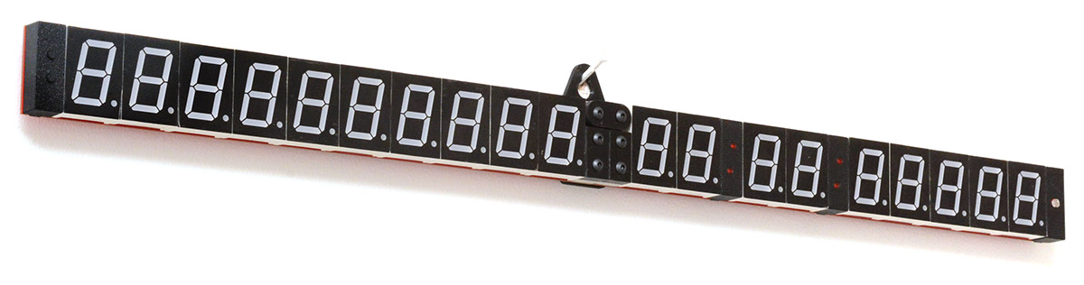
Another option is to hang the unfolded clock from the middle, with this shape that presses onto all six bolts:
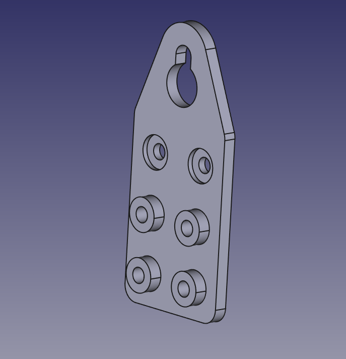
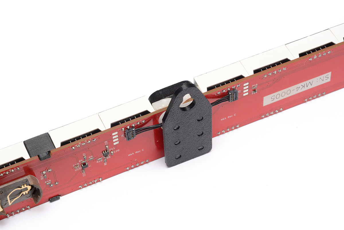
This is pretty secure, the main disadvantage is that it's harder to adjust the clock to make it level. Depending on how you route the cables, that may or may not be an issue.
Or you could combine this method of locking the hinge with the other style of clip to hold it from the ends.
The design files for all of the above wall hangers are in the github repo here.
A few people have remixed the wall hanger designs. A "slim" wallhanger by Teque5 has been shared here. An even slimmer wall hanger that uses double-sided tape by Kevin Thomasson has is here. Files for both are in respective folders in the repo.
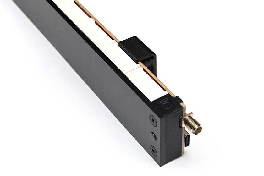
(March 2026) Another wallhanger option, which I have creatively dubbed "Wallhanger 4", clips onto the PCB only.
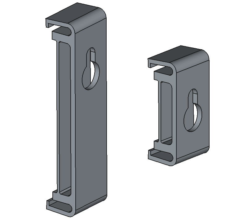
There is a substantial spring pressure in the design, I have no doubt about how securely it holds the clock.
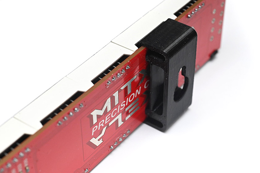
It needs the pins of the digits to be trimmed reasonably flush. Some batches of digits have a different plastic moulding that comes closer to the PCB, in which case you may have to lightly sand the clip to ensure it fits properly, but with some gentle encouragement it should still work.
The main advantage of this hanger is that it will work equally well with the acrylic front cover fitted.
The versions without the keyhole can be used with double-sided tape, or even better, I have found 3M Command strips to work quite well. They are like fancy velcro, which can be readjusted and supposedly removed without residue.
The files for these hangers are in the folder cad/wallhanger4.
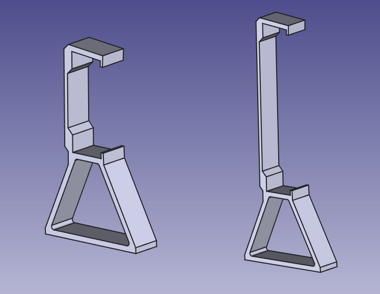
Shelf stand
If you place the clock on a shelf at a reasonable height, from some angles it will be partially occluded. Raising it up by about an inch is enough make it visible. Adapting the above wall hangers, I made these little stands for the clock.
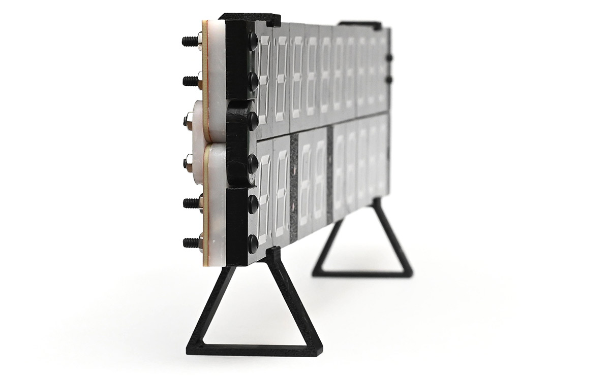
Again there are options for folded and unfolded. For the unfolded position it probably needs three or four of them. They are planar and could potentially be laser-cut.
Again the files are available in the cad folder of the repo.
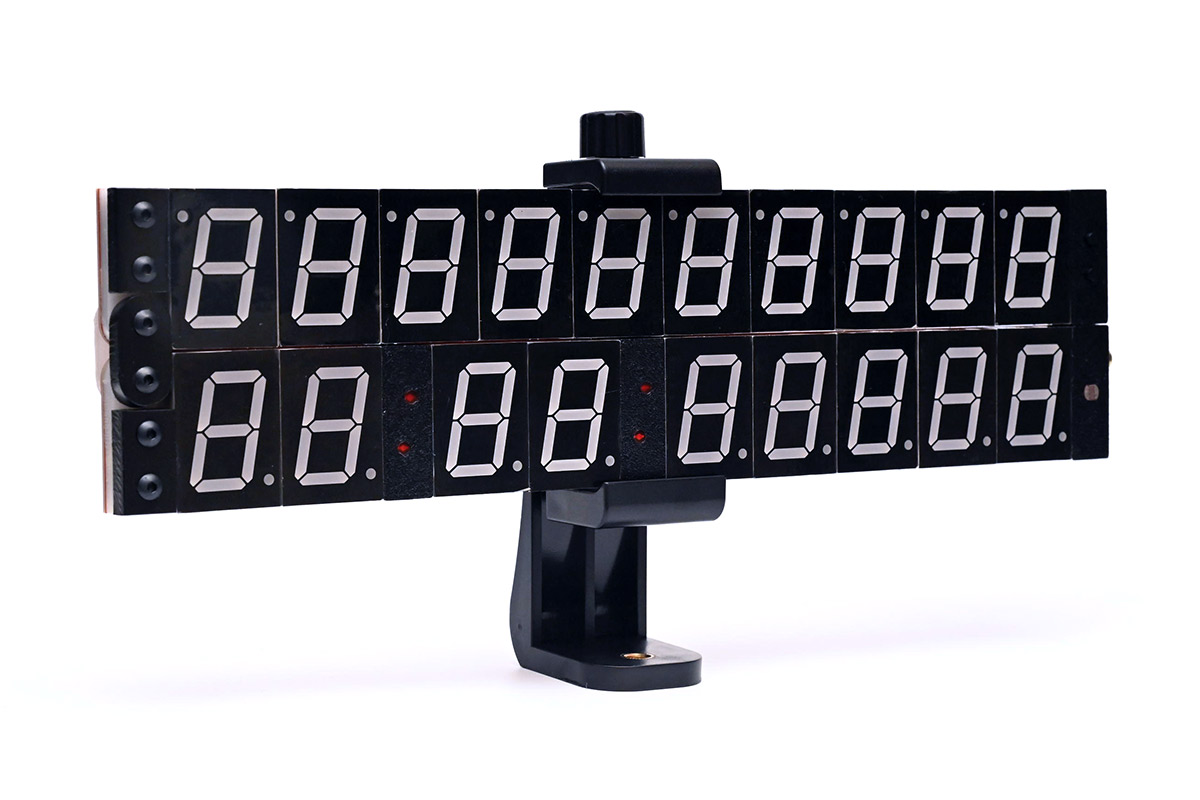
Tripod mount For reference usage, having a threaded mount is very useful. I was prepared to design another custom part here, but I found an existing "Smartphone Tripod Adapter" which works perfectly and cost about £5.

It has a standard 1/4"-20 thread for a tripod or lighting fixture.