
Precision Clock Mk II½
3 May 2019Progress: Completed
This page is the about the development of the first Precision Clock Kit. It was written in August 2018 but I delayed publishing it until the kit was available.
» This kit has now been superseded by the much-improved mark IV clock.
» For instructions on assembling the Mk III kit, click here.
There is also a youtube video of the clock, featuring high-speed footage, and the assembly process with an original musical accompaniment:
Preamble
Gosh, it's been ages since I've posted a proper electronics project. You see, I recently invested in an accordion, which, it transpires, is one of the greatest musical instruments ever invented and so what little spare time I have had has simply been eaten up by it. But now I think we are well overdue for some hardcore electronics.
Precision Clock Mk II has performed spectacularly. It hasn't skipped a beat since I first made it. It has succeeded at being everything a clock should be – it is perfectly accurate and perfectly easy to read. I particularly enjoyed the leap-second that was added at new year's eve in 2016. The clock rolled over to the next year for one second, then back again, then forwards again: exactly the desired behaviour, really.
A not insignificant number of people have expressed their desire for a similar clock. (I particularly enjoyed seeing kh's version with a laser cut case.) The project is relatively simple but involves a huge amount of tedious soldering, which makes it a perfect candidate for an electronic kit with a custom PCB. My friend Tom asked me if I could produce a kit of the clock. I said yes, of course, as soon as I was less busy.
A few years later and the amount of progress on the kit amounted to zero. Tom suggested that he have a go at it, and I whole-heartedly approved of the notion, but the task is nowhere near as simple as it might first appear, and gets even harder when one does not have a reference Precision Clock Mk II hanging on one's wall.
And so it was proposed that we pick a date, collaborate and hammer out a Precision Clock kit in an EDA marathon. Begin!
Plan
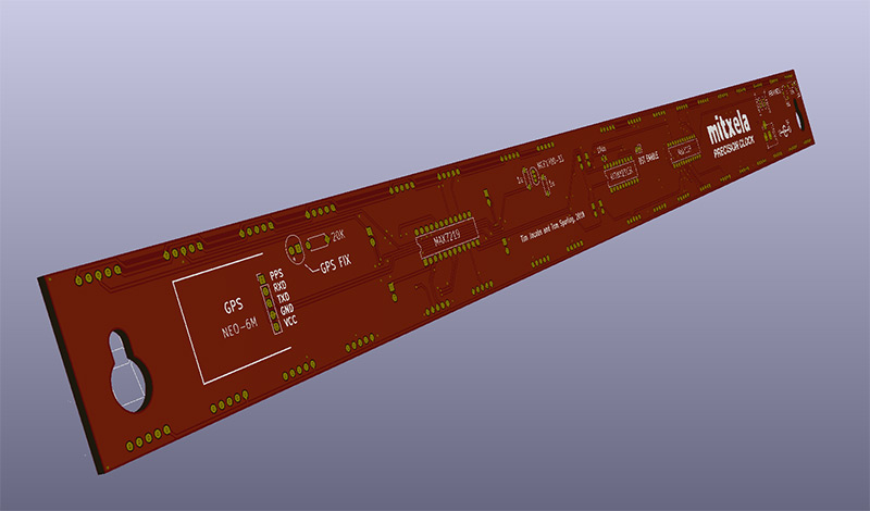
In the original clock, the digits were superglued together to form the body. This time, the main structure of the clock would be the PCB. While I expected to have to split it into multiple PCBs to keep the size within reason, it turns out that ordering a PCB from China that's 50cm long is not at all expensive.We decided to use KiCAD, the open source PCB design software that everyone's talking about. Not only was I keen to learn it, but the free version of EAGLE (which would have been my normal choice) is limited to a certain board size. Not a restriction I usually run into, because most of my projects are so tiny, but this time EAGLE simply wouldn't do.
The most important thing about a kit is that it should be easy to assemble. This means all parts should be through-mount if possible, and their locations should be clearly labelled.
Schematic Capture (paper)
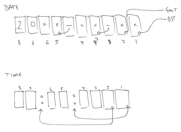
We have a reference clock, first thing to do is produce an exact schematic of it. The circuit is simple but there are hundreds of connections to those digits that we don't want to mess up. We could input this straight into KiCad, but given that it's our first experience with the software and we don't want to risk mistakes, it makes a lot of sense to do an old-fashioned scribble on paper first. It's more than three years since I first did the project, so this is a helpful refresher.
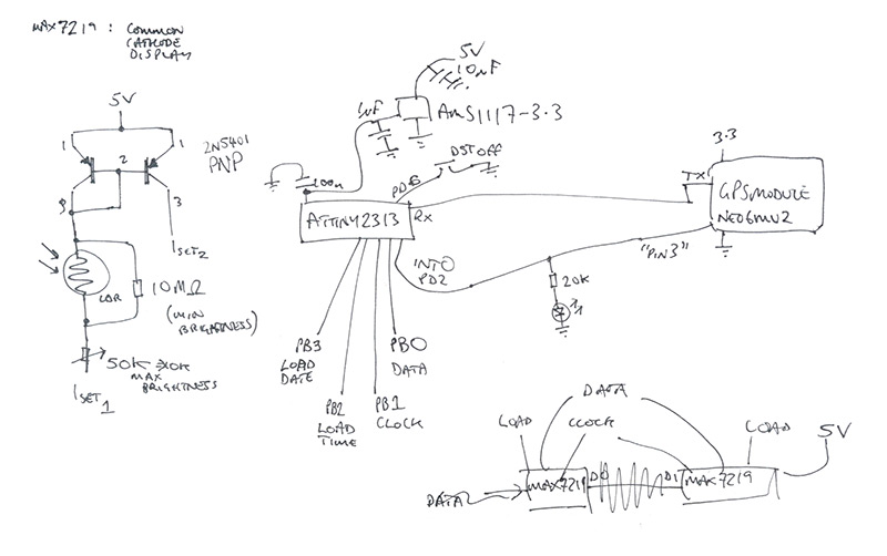
- The shift registers are not wired in series, their data inputs are tied together and the load lines are used as enable pins. See bottom-right of scribble above. It was wired like this so that they can both be addressed at the same speed, and for initialization and stuff they can be loaded in parallel.
- The current mirror is from the 5V line, and the MAX7219 chips are running off 5V too. The only thing the 3.3V regulator is needed for is the GPS module, but the ATtiny is wired to it too.
- Common cathode. All common cathode. Do not forget.
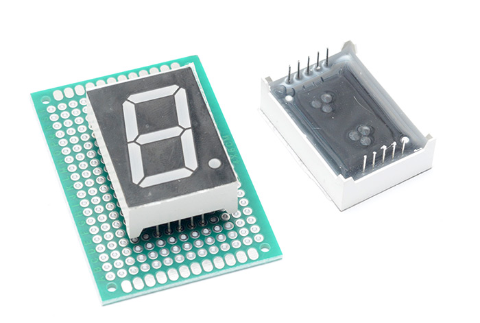
Consulting with the datasheet for the MAX7219 chips we need to refer to the digit display pinouts in the same notation that the shift registers use. The 'units' are .1 inch, we just stuck a display into protoboard and counted the number of holes.
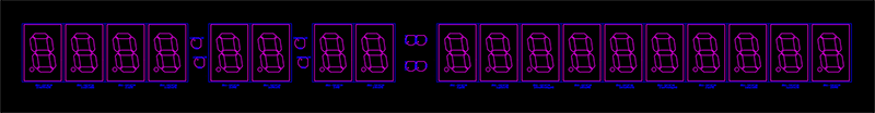
There are 18 digits but the two Maxim chips are only supposed to be able to do 8 each. The unused decimal points of the date digits was used for the hyphens, the DST indicators and the colons were also driven by unused decimal points. Very important to wire this up right.
The colon LEDs are an interesting point. The two LEDs are wired up in parallel, and are driven in constant-current mode. In theory this shouldn't really work, because there is no load-balancing between the LEDs. If one of them has a slightly higher forward voltage than the other, all of the current will go through one LED and not the other. But the fact is, I didn't match the LEDs, and the circuit works. The reason for wiring them like this was to reduce their brightness. On their own, the 3mm LEDs seem a lot brighter than the display segments.
Schematic Capture (KiCad)
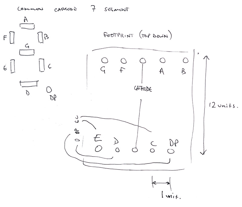
I probably should have taken some notes during this part, but there are lots of tutorials on the process.There are so many 7 segment displays in existence, it might have been possible to find our exact one in the existing libraries, but I don't like the odds. Best to lay out our own footprint exactly. But the schematic symbol, that can be a generic 7seg display. Common cathode!
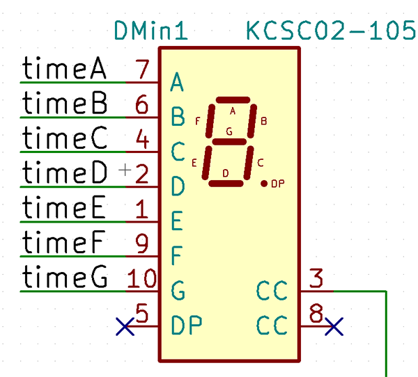
The alphabetical naming of segments does seem to be a fairly standardized thing, or at least, this symbol matches our displays. The two CC pins are connected internally (we double checked), when we come to laying out the traces we might need to switch which pin we've connected to, but we only need to connect to one.
All of the pins are labelled, I think naming signals is the only way a circuit like this can be managed. You'd spend hours drawing nets between all these parts.
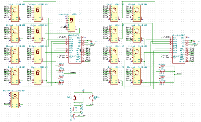
Digits and drivers.
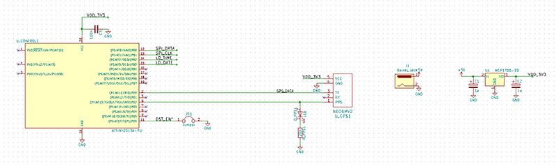
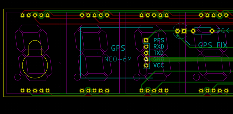
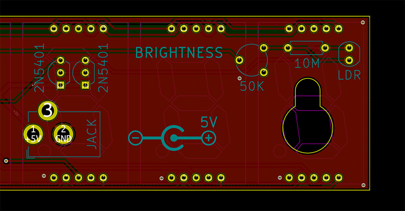
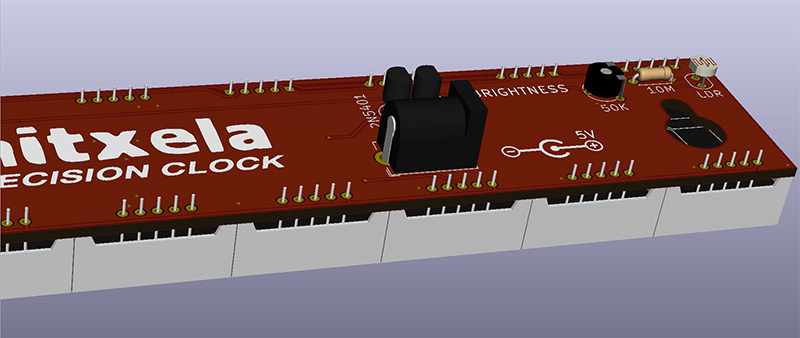
ATtiny, GPS module, power stuff. I couldn't find the exact GPS module I used previously, although it's a standard part on the board (the u-blox neo-6m v2) the little circuit boards they come on have changed a bit. I found and ordered one that also had the PPS signal exposed (I had to solder directly to a pin on the chip for the old clock). Instead of the AMS1117 regulator I did a quick search and found a through-hole 3.3V linear regulator, MCP1700, in order to keep the soldering easy. We also decided to stick a barrel jack on board, one of the generic 5.5mm x 2.1mm types. Tom wanted a USB port, but again I shied away from that because it'd be fine-pitch surface mount soldering.
Footprint Fun
I mentioned that the digits slot into .1-inch protoboard, but it's really important we get the outlines right too. The digits need to be sitting right next to each other, but it's a gamble. Too far apart and it wouldn't look right, too close together and we won't be able to assemble the clock.
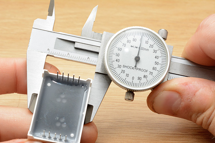
The pin locations are not symmetrical, there's a definite unevenness to the layout. We spent some time sticking digits into protoboard, and although the pins are a standard pitch, sticking two digits into protoboard leaves a big gap between them, almost exactly half a unit. I had every confidence we could get this right, just needed to be careful about it.
We laid out the outline on the Fab layer, and also added an outline to the silkscreen. The silk isn't just decorative, it's actually pretty important to show which way up and on which side of the board the digits go. If the whole PCB is through-mount, without silkscreen one could quite happily assemble the whole thing back to front. Rather than draw the 7-seg digit though, we imported it from another existing footprint.
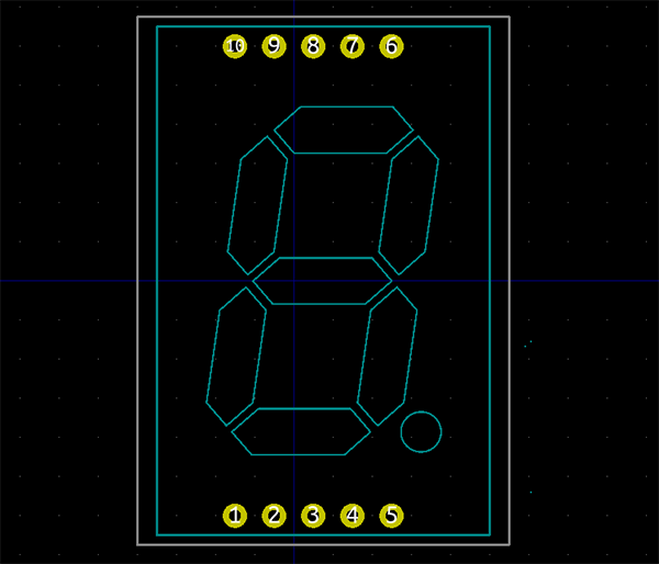
Importing the graphic was not possible within KiCad, potentially this is something the developers are still working on. But the file formats are human readable, and so we can just open up one footprint in a text editor, select the parts we need and copy them into the other footprint file. I'm perfectly comfortable doing this, I do it all the time in EAGLE, which uses XML files. Some people are weirded out by it – you shouldn't be.
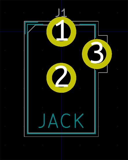
The ATtiny and the MAX chips are standard DIL footprints so nothing worth mentioning there. The GPS module had a .1 inch header. A few TO-92s for the transistors and regulator. One part that needs thinking about is the barrel jack. Instead of round pins, it has thin, flat legs.
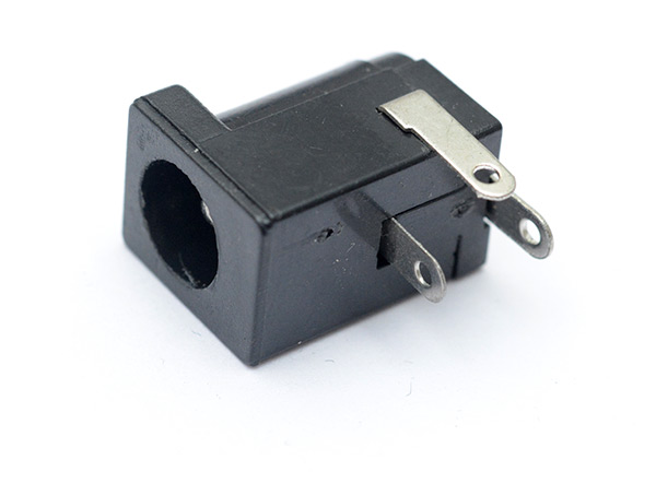
There was a part in the libraries that looked like the right thing for this footprint, but I don't trust it. You have to keep in mind the process that is used to produce a PCB, and at what stage the through-holes are plated. Asking for plated slots is asking for uncertainty. I have, in the past, had boards come back with unplated slots, or even no slots at all, because the routing is done after the through-holes are plated. This opinion may be completely out of date, or even just specific to that one manufacturer that I had problems with, but whatever, let's not take risks. Big, round plated holes that can be done with a drill!
Routing
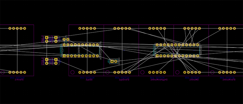
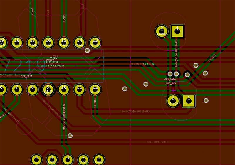
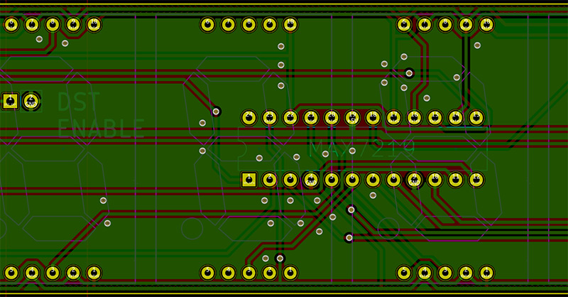
Actually, we're not at that point yet. First we need to place all the important parts in their correct locations. Most important are the displays and the LEDs.We stuck these on the bottom (back) layer, the rest of the parts will go on the top (or as KiCad calls it, the Front). Once we were happy with the placement, their locations were locked.
The rest of the parts can go wherever, but it's worth considering how it's going to be routed. While there's nothing wrong with vias, and there isn't really a limit to how many you can use, I think both of us were very concerned about finding the layout with the fewest crossovers. Evidently the best tactic is to stare at the ratsnest for ages and keep shoving and rotating things around.
At this point I think it was approaching 4am. Having only started at 11pm, the somewhat ambitious idea of kicking out the whole thing in one night was looking rather unrealistic so we decided to call it a day, catch up on sleep and consume lots of tea.
git init
git add -A
git commit
Cleaning up the repo will have to come later. The files are all human readable, at least. More on git in a bit, but this was just the fastest way to share the files from one laptop to another (start an http server on one, and add it as a remote on the other).
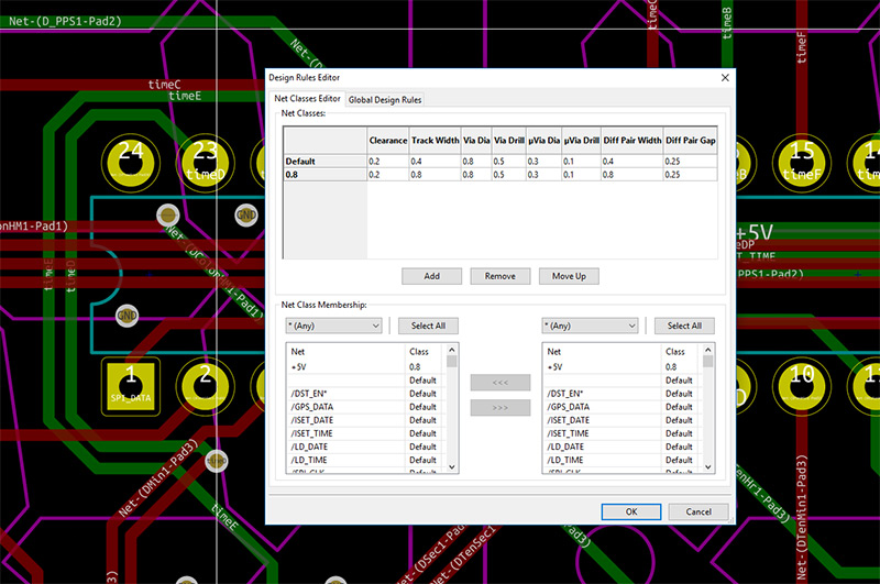
At the start of the next session, we were ready to do some real routing. I'm not sure why the default trace width is so small in KiCad, while I suppose there's nothing wrong with going so small there really isn't any need for it in this case. We're dealing with tiny currents, but thicker traces feel a bit safer to me. We went with 0.8mm for the power input and 0.4mm for everything else. These are set in the design rules, and the trace thicknesses are automatically applied as you route.
KiCad has push-and-shove routing... but I don't like it. I prefer to do it all on manual. This is, after all, a hobbyist project and the only deadline is sunrise. So forgive us for focussing on the aesthetics.
Useful info about laying out in KiCad's PCBNew:
- V toggles between layers, pageup/pagedown select front and back layers.
- B recalculates the ground pour
- Shift-X adds a trace
- D grabs and drags a trace without breaking it
- Square brackets adjust the current layer's opacity, very useful.
Most of the hotkeys are listed next to the options in the context menu. I always turn off "Centre and warp cursor on zoom" in the settings, I have no idea why anyone would want that as the default.
Isolated copper pours are completely pointless except for saving fractions of a penny if you were etching it at home. But is there an aesthetic quality to those little triangles along the edges? Debatable – but Tom wanted them (sorry Tom).
On a two layer board with components on both sides, there isn't a ground layer, so it's important to make sure the ground pours have good continuity throughout. Minimizing the via count does help, mostly through using the legs of components as jumps wherever possible, but there's more to it than that. Every signal has a return path. If there's a ground pour underneath it, the return path is directly under the signal. If the ground pour is broken, or split, or there's a trace cutting through, then the return path has to go around. Always keep this in mind. The area enclosed by the signal and its return path forms a loop, and the more area to this loop, the bigger the inductance, and inductance here means electromagnetic emissions and potentially compromised signal integrity. For this particular project, these shouldn't be concerns, but why do a mediocre design when you can do a good one? Having said that, there's a tendency to keep rerouting things ad infinitum for no real benefit, so it helps to keep the whole picture in perspective.
If you're wondering about the original clock, that probably behaved quite well, because each return path was an individual wire much like the signal wires. A ground pour can make life easier, but only so long as you're careful not to let it cause problems.
Added keyhole cutouts for wall mounting onto the Edge Cuts layer. Quite a lot of thought and debate went into this part.
For the silkscreen layers, we tried to stick to a minimum font size. It's very easy to use a small font in the editor, and be disappointed when the real circuit boards arrive. If you're lucky, it'll be visible with a magnifying glass; if not, it'll be a useless smudge. So find a reference circuit board, measure the font height, and agree not to go smaller than that. In this case we stuck to 1.8mm.
We also had fun doing a little barreljack icon.
Speaking of icons, Tom decided to add a logo, and fair play to him, it was designed and imported using only open source software (primarily inkscape).
![]()
Where does KiCad fall down? I can't stand the lack of rounded traces. You can import files from EAGLE, but any rounded traces get converted to multi-segment straight lines, which looks fine but means you can't really edit them. Whether or not rounded traces have an electrical advantage is totally irrelevant – not being able to do them at all is a disadvantage. There is an experimental extension to KiCad that adds rounded traces, teardrops and via stitching, nominally for RF performance but we all know it's for the aesthetic goodness, but this hasn't been merged, apparently due to the author's incorrect use of git (?). It also seems to use the old rendering engine instead of the OpenGL rendering engine that KiCad uses now. There are some cool videos on Heikki Pulkkinen's youtube page though.
If support for rounded traces and teardrops gets added to KiCad, I would be very happy.
3D modelling
One of the neat things about KiCad is its native support for a 3D rendered model of your board.
Those parts for which we took the standard footprints already have models associated with them, but the custom footprints do not. In order to have our 3D board populated, we need to model the 7 segment displays and the barrel jack. Obviously the best tool to do this is OpenSCAD.
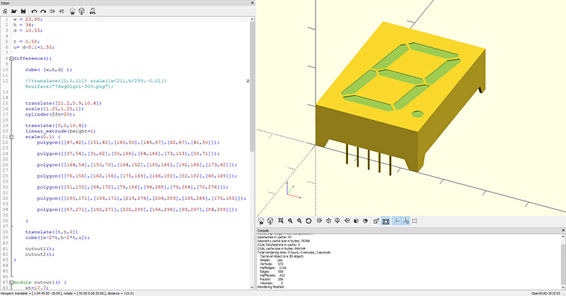
OpenSCAD is 3D modelling for programmers, and I find it exceptionally easy to use. I particularly like doing things like for-loops, and setting sizes to expressions involving variables that can be changed later. Not much of that is needed this time though. Most of this is just cubes following calliper readings, but for the segments themselves I ended up tracing the outline of an image. At first I threshold'd and imported the image, but having a separate cube for every pixel made the program quite sluggish, I'm not sure how KiCad would have behaved with eighteen of them on the page.
The barrel jack was modelled as well, following exact measurements.
There are tutorials out there for the next steps, but in summary we export an STL file from OpenSCAD and import it into Wings3D where we can do some touchups and add materials (colours) to various faces. Export it as a VRML (.wrl) file and within KiCad's footprint editor, head to footprint properties and select the 3D settings tab. Here it can be imported, scaled and positioned. Either here, or earlier in the process, a conversion between metric and imperial will probably have to take place, which means a scale factor of 25.4.
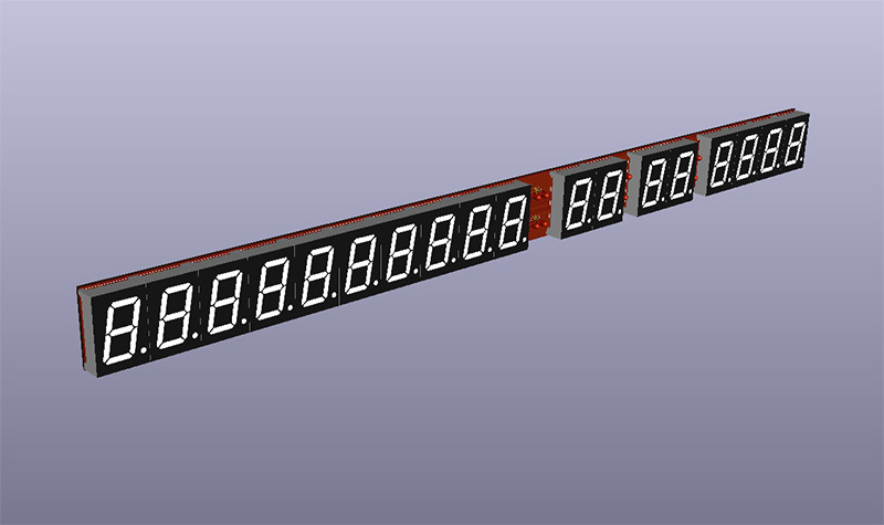
The displays were measured and modelled separately to when we did the footprints, so this serves as a great double-check that they're going to fit together correctly.
Now we can see that the barrel jack is by far the tallest part. Yes, it was useful doing the 3D modelling and not just for fun, honest. There was actually a concern with where the power cable goes, and whether it would interfere with the keyhole mounts, if we choose to use them. We ended up moving the barrel jack over a bit just in case.
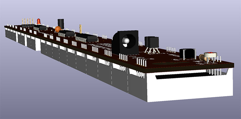
The 3D model also helps as a generic layer inspection tool, a lot of the pre-order sanity checking that's normally done by staring at gerbers for hours can be done here instead. Neat.
KiCad and Git
There was some mucking about and cleanup of the folder structure in order to have all the 3D models included and tracked. This involved switching all of the paths to be relative to the project dir using the environment variable${KIPRJMOD}. Tom's installation of KiCad (from the Arch package repositories) didn't come with any 3D models at all, so while I was adding our custom ones I fixed the rest to be tracked in the repo too. Git can track anything, but it's intended for source code. It counts changes on a number-of-lines basis. While KiCad uses human readable save files, it doesn't play too well with git. As you might expect, even tiny changes to a visual design can cause large blocks of data to be reordered, and so something small may look like something huge as a text diff. Not only that, but there are timestamps appended all over the place. I'm not sure what the point of these are, some of them are even in the future. One could potentially use a git filter to hide these from the commit (and smudge again when checking out) but even then I don't think you could quickly make sense of a diff.
What's needed is a visual diff, so you can quickly scroll through the versions and see what changed where. A number of people have tried to implement this, I found a few different approaches, but nothing did quite what I wanted, and certainly, nothing was straight forward.
There are a substantial number of python scripts in the KiCad installation folder, and among these is pcbnew.py, a wrapper for a host of C functions that are available. Within the share/kicad/demos/python_scripts_examples folder there is a script called plot_board.py, which allows us to scriptably generate gerbers, PDFs and hopefully SVG files from kicad_pcb files. It takes a bit of wrenching to get this to run outside of its normal environment (the console within PCBnew) but it's not impossible. From here, if we can generate SVG files, we can throw them into inkscape's CLI to convert them to PNGs, and then pass them off to an image diff tool such as ImageMagick's compare.
If all of that can be wrapped in a shell script, it could then be dropped in to git as an external difftool. As ugly as this solution sounds, it should in theory work, and once configured, work seamlessly.
I didn't get it working yet, we'd already finished the PCB by the time I was looking into this, but perhaps we'll have another attempt for the next project.
Aside: GPS modules
As mentioned above, the exact GPS module I used in the MkII isn't available any more. It was just a generic uBlox module from eBay. There are a few different ones available now, they all have the same NEO-6M V2 chip on board so they should all behave the same. We'd picked one with the PPS signal on the header, and added it to the board based on the thumbnail picture in the listing. To be on the safe side, I also ordered one of each of the other commonly available modules.
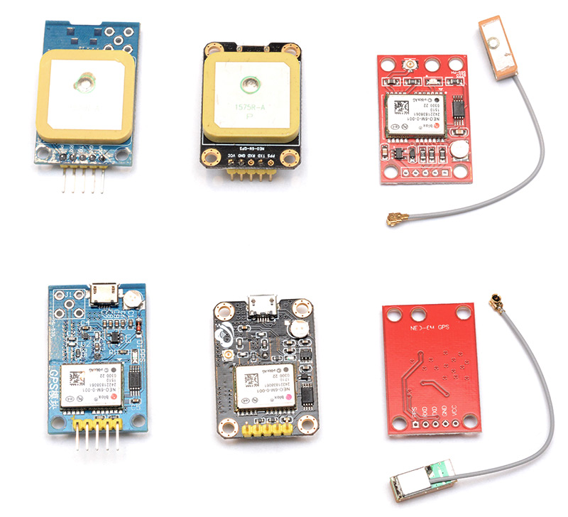
Not only are these guys different prices, they have annoying differences between them. A common feature all of them turned out to have is an LED on board, linked to the PPS signal. This makes the GPS-Fix LED on our PCB a bit redundant, but it doesn't hurt to leave the footprint there for it. The most annoying thing is that although they're all on a .1 inch header, they have different pin arrangements! One of them is nearly identical to the other except RX and TX are swapped.
The blue board had seemed the most promising, it has an onboard antenna, and also a footprint for an optional SMA connector for an external antenna. But for some reason, this module behaved the worst out of all of them. Maybe there's some configuration needed, to select the onboard antenna? I left that module turned on for 24 hours, and it still hadn't found a single satellite.
The other modules found their GPS fix in about half an hour. This is a completely cold start, remember. As far as the module is concerned, it could be anywhere on the planet, at any time in this century. In order to do a warm start, or a hot start, they have little battery backups on board to remember the last fix. Disappointingly none of these new modules appeared to have a working battery. It's the little cylindrical silver part, so all three of them have it fitted, but the voltage reads almost zero. It may actually be a supercapacitor, in fact. But it's not charging up. Perhaps the supplier of these parts sent duff ones to all the GPS module makers.
My MkII clock has the same component, but it's functioning. If I unplug the clock for five minutes, and turn it on again, it gets the correct time straight away and finds the fix again in a couple of seconds. These modules, when the power is cut even for just a minute, have to do a full cold start again. I suppose in the case of a wall-mounted clock, especially one with auto-adjusting brightness levels, it's not much of a problem because the clock should be on all of the time, but it's still a little bit annoying.
To my surprise, all three of these modules have regulators on board, which lets them be powered from either 5V or 3.3V. The original module I used was 3.3V only, and is the entire reason we have that regulator on our PCB. If we knew that all modules now support 5V, maybe we could remove the regulator from the board and reduce the component count, but it's probably not worth the risk. It's quite possible that in the future the best choice of module may be different.
We decided to choose the red unit with the detachable antenna. It has the right pinout, it functions perfectly, and as a bonus it's also the cheapest of the three.
The first prototype (of the mark 2½)
The last step of the design process is to generate and examine the gerbers for mistakes. Common mistakes include missing the stopmask on some of the footprints, exporting things to the wrong layers, or producing gerbers that are mangled in some way due to the plotting process, such as forming millions of tiny squares instead of one big one.Having pored over the gerber files long enough, it was time to order from China and wait.
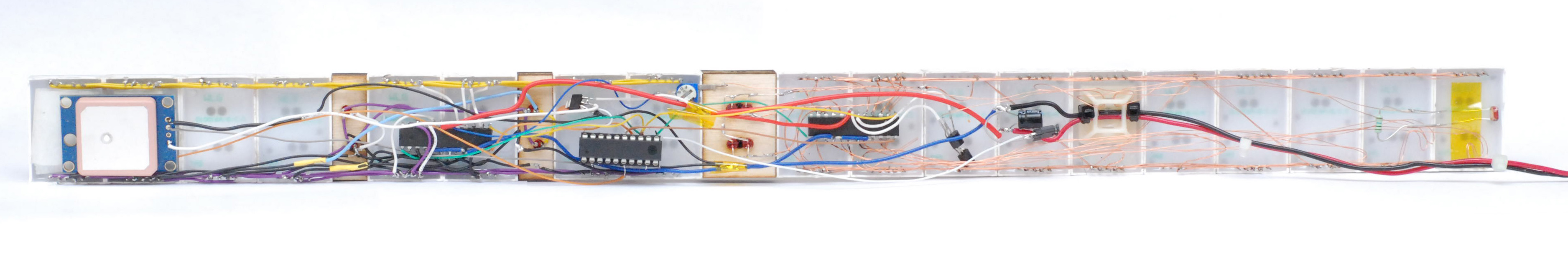
Six days later and the boards appeared at my doorstep.
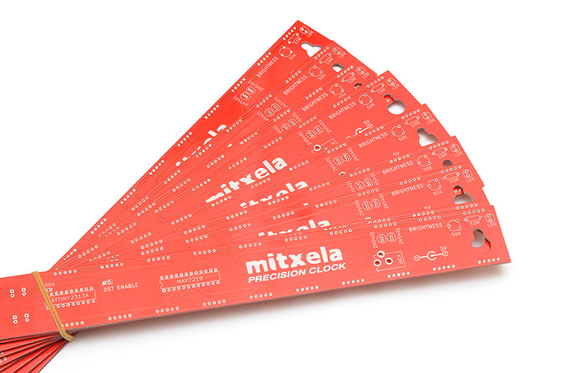
Exciting! They look fine. In fact they look remarkably similar to the 3D render. Funny that.
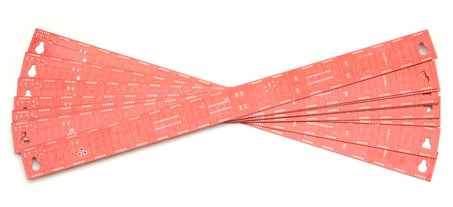
We did a quick test fit of the 7 segment displays to check how close together they were and it seemed to be right on the money. But the digits have to be soldered last, as they cover up the legs of all the components on the other side.
The only real comment during this process is that the legs of the TO-92 parts were quite close together, making them slightly harder to solder than the other parts. For the next revision I widened the footprints. There were also a couple of minor points about the silkscreen. The big logo overlaps some of the vias, and it wasn't easy to spot this on the initial 3D render. They were only random ground plane vias anyway, so I shifted them a bit on the design. I also decided to mount the DST jumper at a right angle, which means the text is partially covered. For the next revision I just shifted this over so it's visible regardless.
One hiccup that occurred was that the batch of ATtiny2313 chips I'd bought turned out to be duff. Couldn't get them to program at all. Perhaps they'd respond to a high voltage programmer, I don't know. Never had something like that before. In order to test the clock, then, I soldered a DIP socket in place of the chip, and plugged in the already-programmed ATtiny2313 chip that I pulled out of the Mk II. With this, we were able to confirm that the electrically, the circuit was fine (there was a very real possibility of having jumbled up all those labels on the schematic).
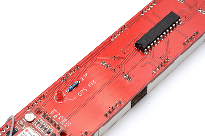
This GPS module has a dangling antenna. Hadn't really thought about where it was going to go, so I just taped it on top for now.

Laser Cutting
The colons are simple, but the timezone text in the middle is a tricky one. The LEDs are mounted at the back, and I cut out wooden spacers as before.
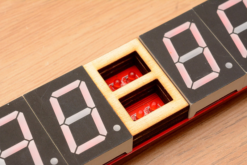
Part of the problem with the GMT/BST text on the previous clock is that the diffuser was behind the text as I etched it. I tried something different this time. I stuck some black electrical tape onto a metal ruler, laser-etched the text into it, then peeled it off and carefully stuck it onto some translucent plastic. This definitely worked better than before, the diffuser is much brighter like this, but the transferral of the black tape could have been more precise.
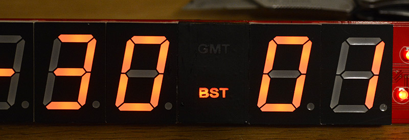
We will need to think up a way of producing a bunch of these diffuser/stencil combos.
The Pursuit of Precision
The ATtiny2313 seems harder to get hold of now, so I ordered a pack of the newer ATtiny4313s instead, which is the same but with double the memory. I flashed a chip, stuck it into the prototype and waited.Something strange started to happen. The seconds digit was flickering, back and forth. It took me a moment to realize what was happening.
The GPS module has a PPS (Pulse-Per-Second) output, and on the rising edge of this signal, that's when the 'seconds' of the clock should read zero. Then, there is the slow UART output of NMEA strings, at 9600 baud, and somewhere in there is a date and time string which represents the exact time of when the last PPS signal happened. This string could be a few hundred milliseconds after the pulse.
The way the clock handles this is by having an entire clock overflow routine, so it can tick by itself, even at midnight on the 28th of February. When a pulse comes in, it advances the centiseconds to 99, and manually fires the overflow routine, so that the display reads one second ahead of the last NMEA message we had.
This worked beautifully (to the human eye at least) on the original Mk II. But the ticking of the centiseconds is divided down from the main oscillator on the chip, which is just the internal RC oscillator that's only calibrated to within a few percent. On the old chip, it just so happened that its oscillator was slightly slow, and on the new chip the oscillator was very slightly fast. At the moment when the PPS rises, the old chip was probably reading 97 or 98 centiseconds, and ticked over fine. But on the new chip, at that moment the centiseconds had ticked over to 00 or 01, and the routine was advancing it another second ahead. When the string came in around 20 centiseconds later, it corrects the mistake, and hence the flicker.
One possibly easy fix for this is to put a crystal oscillator on the board so that the ATtiny runs at an accurate speed, but why should we have to? We have an extremely accurate 1PPS signal already, it seems stupid to stick another oscillator on there.
The internal oscillator can be calibrated on the fly by writing to the OSCCAL register, but I'm loathe to do this because every time you change it, the processor can stutter a little bit and maybe miss a few cycles. It's also a non-linear mapping, if you want to increase the frequency by a certain percentage, the only way to do so is by binary search.
Much better to alter the timer compare register used for the centisecond interrupt. Not only is it 16-bit so we have finer grain control over it, it's also perfectly linear, and we can muck about with it without worrying about disrupting any other timings.
I added a routine into the rising-edge PPS interrupt to do the following:
- if the centiseconds reads less than 50, assume it's overflowed and slow the timer down slightly
- if the centiseconds reads less than 99, it's running slow, so speed the timer up slightly.
Unfortunately this didn't work quite as well as I planned. I eventually stuck an 8Mhz crystal on the chip to be sure that it was running at the right speed, and so no adjustment should have been necessary, but even then it took a long time to stabilize, having to adjust the initial value by more than 1%. That's not right...
A little more thought and the answer is obvious: the 1PPS interrupt adds an extra tick to the clock. The centiseconds is running 100 times per second, so that's 101 ticks per second in total. D'oh! Once I'd got it to zero the centiseconds timer register and clear its flag during the PPS interrupt, things started to behave properly.
At this point it looked correct to the human eye. But our eyes can't see things at 100 frames per second. Was it really rolling over correctly? Did it hit 99 or not? I felt like I'd invested enough into this that I should at least have an answer. So I did the only sane thing to do at this point, and bought a camera that can shoot at 1000FPS.
The answer was: no, it was not ticking correctly, but now we can see what's going on, it should be easy to make it do so. Over the next few days I continuously tweaked the algorithm. How accurate should it be? I suppose within 10ms would be acceptable, as that's the resolution of the display. But we have an LED on the PPS signal, so at the very least the display should read 00 at the same time that the LED lights up. The self-calibrating routine can be simpler than I originally thought. It's better to assume that the ticking is never spot-on, so if it's not fast, then it's slow.
At 1000FPS, expanded to 30FPS, 2 seconds of video takes more than a minute to play back. The centiseconds changes every ten frames, but at this speed, the pulsing of the matrixed display becomes visible. The illumination of the desk by my computer monitor becomes a strobe light: the backlight is dimmed by pulsing it every few milliseconds. My illuminated keyboard pulsates too, but at a different frequency. At 1000FPS, even the shakiest hands feel like a smooth dolly shot.
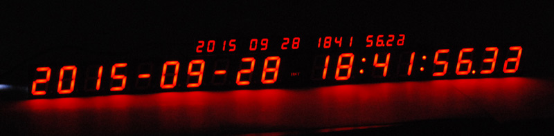
Having spent the best part of a day in this weird, pulsating, slow motion world, we finally ended up with this.
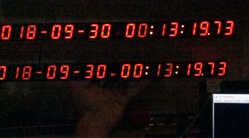
Above is a still frame from the 1000FPS footage. (Actually, it's a few frames stacked together, so that the entire matrixed display is illuminated.) Two clocks, the Mk II and the new prototype, operating independently with their own GPS modules, and displaying the same time to the centisecond. The displays both update within one frame of each other, so they are synchronized within 1 millisecond. Satisfying.
Timezone Troubles and the Saving of the Daylight
This was the part I was dreading most. To sell a clock kit, we need the clock to work in other timezones.
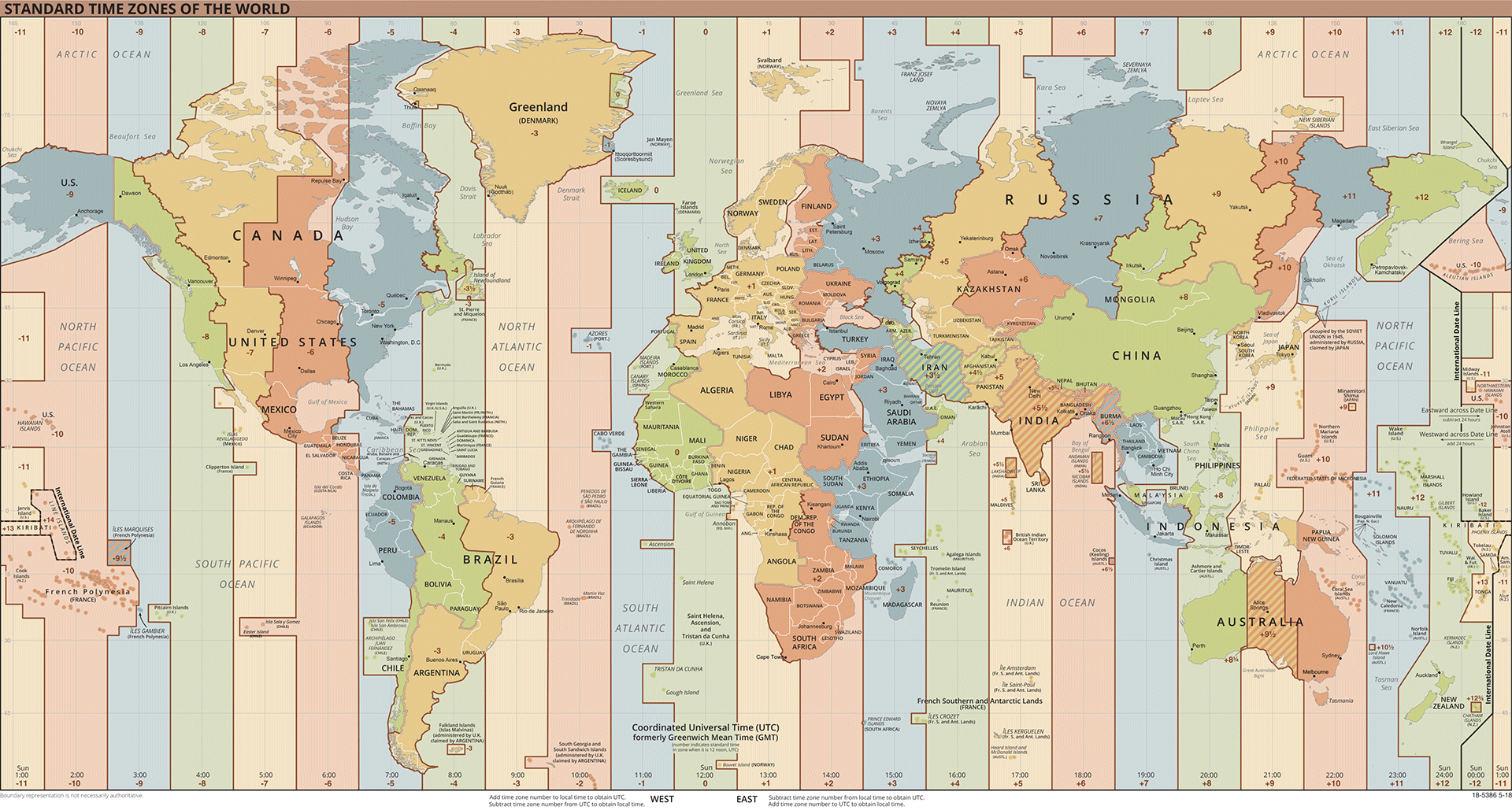
The first thing I should clear up is that even though we have a GPS unit, there's simply no way we can work out which country we're in and apply an offset. There's the tz database which describes the timezones of the world, but even forgetting the fact that it frequently changes, the tz database is huge. The shapefile that describes the timezone boundaries is about 15 megabytes. Given that our processor has 2kB of program memory and just 128 bytes of RAM, the idea to "just use the tz database" is simply out of the question.
The best way of building a fully automatic GPS clock would be to also give it internet access, maybe WiFi, so that it could query its timezone from its location using an online service. I suppose another option, if we really didn't want to have it depend on a network connection, would be to include an SD card slot which stores the database. That would allow updates at least. It would be a fairly substantial change to the hardware though.
So what can we hope to do instead? The best solution is to compile specific firmware images for each timezone using preprocessor directives. So if a clock is to be used in New York, we flash the chip with the New York hex file. While I did consider using the spare pins of the chip to have a matrix of jumpers to input the timezone that way, it's just too complex. We need to support hour-offsets from -12 to +14, and also have half-hour offsets for some places, and even 15 minute offsets for others. Then there's the daylight saving time, which is a nightmare. Even implementing it for just one country was a nightmare. There are so many different permutations that there's too much to fit onto jumpers or dip switches.
A brief glance at the wikipedia page for daylight saving time by country shows just what a daunting task this is. Even after stripping the historical data there are a large number of permutations. It gets worse when you think about at what time the DST takes affect: some countries apply it at 1AM UTC, others at 1AM local time. In our clock, that would mean adding the timezone offset, then checking for DST and adding an offset again if it matches.
I took the list from wikipedia and cut out all of the notes and exceptions to just get a basic overview of DST across the world.
| Northern Hemisphere | |||
|---|---|---|---|
| Country | Continent | DST Starts | DST Ends |
| Israel | Asia | Friday before last Sunday March | Last Sunday October |
| Jordan | Asia | Last Friday March | Last Friday October |
| Syria | Asia | Last Friday March | Last Friday October |
| Akrotiri and Dhekelia (UK) | Europe | Last Sunday March | Last Sunday October |
| Albania | Europe | Last Sunday March | Last Sunday October |
| Andorra | Europe | Last Sunday March | Last Sunday October |
| Bosnia and Herzegovina | Europe | Last Sunday March | Last Sunday October |
| Faroe Islands (DK) | Europe | Last Sunday March | Last Sunday October |
| Finland | Europe | Last Sunday March | Last Sunday October |
| Holy See | Europe | Last Sunday March | Last Sunday October |
| Kosovo | Europe | Last Sunday March | Last Sunday October |
| Lebanon | Asia | Last Sunday March | Last Sunday October |
| Liechtenstein | Europe | Last Sunday March | Last Sunday October |
| Republic of Macedonia | Europe | Last Sunday March | Last Sunday October |
| Moldova | Europe | Last Sunday March | Last Sunday October |
| Monaco | Europe | Last Sunday March | Last Sunday October |
| Montenegro | Europe | Last Sunday March | Last Sunday October |
| Morocco | Africa | Last Sunday March | Last Sunday October |
| Ukraine | Europe | Last Sunday March | Last Sunday October |
| Western Sahara | Africa | Last Sunday March | Last Sunday October |
| San Marino | Europe | Last Sunday March | Last Sunday October |
| Austria | Europe | Last Sunday March at 01:00 UTC | Last Sunday October at 01:00 UTC |
| Belgium | Europe | Last Sunday March at 01:00 UTC | Last Sunday October at 01:00 UTC |
| Bulgaria | Europe | Last Sunday March at 01:00 UTC | Last Sunday October at 01:00 UTC |
| Croatia | Europe | Last Sunday March at 01:00 UTC | Last Sunday October at 01:00 UTC |
| Cyprus | Europe | Last Sunday March at 01:00 UTC | Last Sunday October at 01:00 UTC |
| Czech Republic | Europe | Last Sunday March at 01:00 UTC | Last Sunday October at 01:00 UTC |
| Denmark | Europe | Last Sunday March at 01:00 UTC | Last Sunday October at 01:00 UTC |
| Estonia | Europe | Last Sunday March at 01:00 UTC | Last Sunday October at 01:00 UTC |
| France | Europe | Last Sunday March at 01:00 UTC | Last Sunday October at 01:00 UTC |
| Germany | Europe | Last Sunday March at 01:00 UTC | Last Sunday October at 01:00 UTC |
| Greece | Europe | Last Sunday March at 01:00 UTC | Last Sunday October at 01:00 UTC |
| Guernsey (UK) | Europe | Last Sunday March at 01:00 UTC | Last Sunday October at 01:00 UTC |
| Hungary | Europe | Last Sunday March at 01:00 UTC | Last Sunday October at 01:00 UTC |
| Republic of Ireland | Europe | Last Sunday March at 01:00 UTC | Last Sunday October at 01:00 UTC |
| Isle of Man (UK) | Europe | Last Sunday March at 01:00 UTC | Last Sunday October at 01:00 UTC |
| Italy | Europe | Last Sunday March at 01:00 UTC | Last Sunday October at 01:00 UTC |
| Jersey (UK) | Europe | Last Sunday March at 01:00 UTC | Last Sunday October at 01:00 UTC |
| Latvia | Europe | Last Sunday March at 01:00 UTC | Last Sunday October at 01:00 UTC |
| Lithuania | Europe | Last Sunday March at 01:00 UTC | Last Sunday October at 01:00 UTC |
| Luxembourg | Europe | Last Sunday March at 01:00 UTC | Last Sunday October at 01:00 UTC |
| Malta | Europe | Last Sunday March at 01:00 UTC | Last Sunday October at 01:00 UTC |
| Netherlands | Europe | Last Sunday March at 01:00 UTC | Last Sunday October at 01:00 UTC |
| Norway | Europe | Last Sunday March at 01:00 UTC | Last Sunday October at 01:00 UTC |
| Poland | Europe | Last Sunday March at 01:00 UTC | Last Sunday October at 01:00 UTC |
| Portugal | Europe | Last Sunday March at 01:00 UTC | Last Sunday October at 01:00 UTC |
| Romania | Europe | Last Sunday March at 01:00 UTC | Last Sunday October at 01:00 UTC |
| Serbia | Europe | Last Sunday March at 01:00 UTC | Last Sunday October at 01:00 UTC |
| Slovakia | Europe | Last Sunday March at 01:00 UTC | Last Sunday October at 01:00 UTC |
| Slovenia | Europe | Last Sunday March at 01:00 UTC | Last Sunday October at 01:00 UTC |
| Spain | Europe | Last Sunday March at 01:00 UTC | Last Sunday October at 01:00 UTC |
| Sweden | Europe | Last Sunday March at 01:00 UTC | Last Sunday October at 01:00 UTC |
| Switzerland | Europe | Last Sunday March at 01:00 UTC | Last Sunday October at 01:00 UTC |
| United Kingdom | Europe | Last Sunday March at 01:00 UTC | Last Sunday October at 01:00 UTC |
| Iran | Asia | March 21-22 | September 21-22 |
| Greenland (DK) | North America | Saturday before last Sunday March at 22:00 local time | Saturday before last Sunday October at 23:00 local time |
| Bahamas | North America | Second Sunday March | First Sunday November |
| Bermuda (UK) | North America | Second Sunday March | First Sunday November |
| Cuba | Central America | Second Sunday March | First Sunday November |
| Haiti | Central America | Second Sunday March | First Sunday November |
| Saint Pierre and Miquelon (FR) | North America | Second Sunday March | First Sunday November |
| United States | North America | Second Sunday March | First Sunday November |
| Canada | North America | Second Sunday March at 2:00 a.m. (for most of Canada) | First Sunday November at 2:00 a.m. (for most of Canada) |
| Mexico | North America | First Sunday April | Last Sunday October |
| Southern Hemisphere | |||
| Chile | South America | Second Sunday August | Second Sunday May |
| New Zealand | Oceania | Last Sunday September | First Sunday April |
| Samoa | Oceania | Last Sunday September | First Sunday April |
| Fiji | Oceania | First Sunday November | Third Sunday January |
| Brazil | South America | First Sunday November at 12:00 am | Third Sunday February at 12:00 am |
| Australia | Oceania | First Sunday October | First Sunday April |
| Paraguay | South America | First Sunday October | Fourth Sunday March |
Good that most of Europe sticks to the same rules... unfortunately most of Europe will be abandoning DST in 2019 anyway. We can create multiple lookup tables for most of this, and use preprocessor macros to include the correct ones. The southern hemisphere will need to have the DST code rewritten, since of course, their DST covers new year.
I created a little javascript program that reads all of these silly dates (yes, even "Saturday before last Sunday March") and spits out the lookup tables we need. Even though "First Sunday November" appears in two different coloumns, we need to make sure to include it twice in the #ifdef stuff. The tables have to be the same size and in the same place, or it'll break the lookup logic. It's always hard to decide how to work with this, at one extreme it becomes unreadably interweaved and the other it's tediously bloated with too many conditions. I rewrote the code, splitting it into three sections for the negative, positive and zero offsets. Within these #ifdefs there are further conditions for if it's northern or southern hemisphere.
The interesting thing is that although the source code is now substantially longer, because it's all preprocessor stuff and conditionally included code, the resulting hex file is basically the same size that it was beforehand, and will still fit onto the ATtiny2313.
Finally I added a few more conditionally included bits of code, to deal with the Annoying Timezones. India is at +5:30, Nepal is at +5:45 and Newfoundland is at -3:30 except for during summer where it's at -2:30. Adding minute offsets is just more of the same gruntwork as before.
There are so many timezones, so many permutations, that I just cannot be bothered to test them all. Perhaps if it was easy enough to construct a test suite, maybe to systematically send various dates and times as pretend NMEA strings and see what it says, but even then it would still take ages. I'm not even sure if the generated lookup tables are correct. At the end of all that, theoretically, basic support is in place for all timezones, and nearly all daylight saving times. The edge cases can have a fixed offset, and just use the DST jumper to change it over as they please.
I did not yet implement that last little hiccup, the fact that DST changes sometimes happen at local time. This wouldn't be impossible to add, but for now I left it with all changes happening at 1AM UTC.
Maximum Jitter
Well, what is it? We've gotten the clock to tick over exactly on the PPS mark, but all that timezone adjustment stuff must take a finite amount of time to process, and it happens in the middle of a second, not near the end, where we've been looking. The timer that fires the centiseconds interrupt keeps ticking while the interrupts are disabled, as in while the timezone is being calculated, but so long as that lasts less than 10ms everything should stay on track. I don't think it's likely that our routine could take long enough to actually throw off the ticking, but it's possible that it delays the interrupt from firing for a while in some cases, leading to an occasional freeze of the display, with one centisecond lasting a little longer, then the next being shorter to compensate. In the absolute worst case scenario, the end of the UART string containing the time and date arrives exactly as the centiseconds interrupt was about to fire.I tried filming the situation. Luckily I'd rewritten the behaviour of the colons' flashing to be based on whether or not we have a GPS fix, and I chose to do this by looking at the NMEA string, not whether the PPS is active. So this functions as a kind of early warning of when the processing is going to happen. The results were inconclusive. Stepping through the footage frame-by-frame, occasionally I'd catch a centisecond last 11 frames instead of 10, but a difference of one frame could be due to a number of things.
The only thing that would quell my curiosity on this matter would be a mathematical analysis of the situation. I walked through the worst case scenario: the last day of daylight saving time in the western hemisphere with a fractional timezone offset, and counted the number of instructions. It came out at 105 (so roughly 105 cycles), which is positively tiny compared to the code that bit-bangs the serial data, which also has to run while interrupts are disabled, since it includes delay routines. That code lasts for about 3300 cycles, and at 8MHz each cycle lasts 125ns. The whole period of disabled interrupts ends up being about 0.42ms then. I think we can live with that.
At this point, the clock kit is still not finished. We need to produce an instruction manual. We also need to buy all of the parts in bulk. But all that's boring – let's do something more interesting.
Extended precision, or earning our half mark
Consider the truth of the following statements.- We own a camera that can measure to 1ms, but our clock is only precise to 10ms.
- With the completion of this kit, anyone can own a GPS synchronized centisecond clock, so the original MKII is no longer exceptional.
- There has been a general lack of fiddly deadbug soldering on this page so far.
Tom described the idea of adding an extra digit of precision to the clock as, "taking a completed project, and making it incomplete". I think he might have a point – but that won't stop me!
Centiseconds were chosen as a resolution because it's pretty much the limit of what can be seen (as motion) to the human eye. It also conveniently aligned with the method of driving the display, both in terms of the number of digits and the fact that the display is matrixed. As we saw in the slowmo footage, the serially driven display driver is running with a period of a couple of milliseconds, so it appears to flicker. Even if we could clock the data out fast enough, a milliseconds digit wouldn't display coherently.
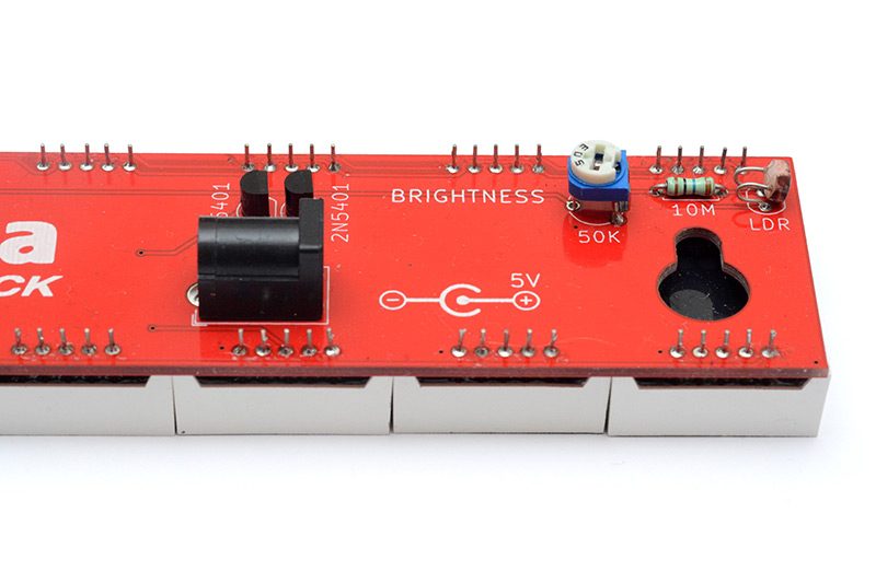
Naturally the solution is direct drive of the segments. An additional microcontroller, with its sub-microsecond resolution on its GPIO pins, can easily have full control over the last digit. The funny thing is that it doesn't even need to know the time. There's the 1PPS signal from the GPS unit, where the display should read zero. Then it just needs to count from zero to nine, ticking at the millisecond, counting to a thousand before the next PPS tick. Since both microcontrollers sync to this signal, it'll all be swell. It does raise the interesting idea of building a clock with a separate microcontroller for each digit, where each one listens to the GPS, calibrates and syncs itself to the pulses, and happily ticks away independently. Why one would be so inclined to do this, I cannot say.
My concern with the extra digit wasn't about timing, though. The auto-brightness circuit has no capacity for extra digits. The reference current produced at the LDR is duplicated in the PNP current mirror, then both maxim chips feed that into their driver transistors, which have a current gain, according to the datasheet, of nominally 100. One of the features of a current mirror is that the transistors can be stacked. If you want more copies of the current, you only need to wire up another matched transistor and link the bases together.
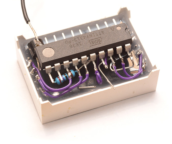
So – let's tap into that brightness circuit, copy the current with another PNP, then drive the digits with a current gain of about 100. I attempted this with a single NPN (think it was a 2n2222), on the common cathode of the display.
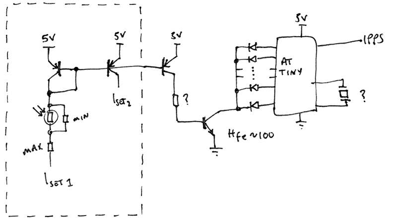
Dashed line represents the existing brightness control circuit on the clock. The question marks cover whether to limit the base current to the NPN and whether to stick a crystal on the chip. Since we've got the PPS signal, we can pull the same self-calibration trick again, so I decided to leave that off. The limiting resistors I chose arbitrarily since I planned to play around with the values. However, that ended up being pretty difficult after my rather shortsighted assembly tactic.
While it's true that it should be possible to stick extra transistors into the current mirror and have more duplicates of the reference current, each of these transistors is going to draw some (small) current from the junction and throw the mirror off slightly. Since the reference current is used directly for half of the display, this means that one half, and the extra digit, appear as a slightly different brightness. We could have the reference current on its own, and have all three sections on separate transistors, or we could replace the current mirror with a FET-based current mirror which shouldn't have this problem, or we could even replace the simple current mirror with one of the more complex circuits that has better performance – but to be honest, I don't want to alter the original MkII clock too much. The cop-out solution is to stick another LDR on the extra digit, and have its circuit completely independent, except for the PPS signal.
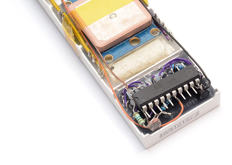
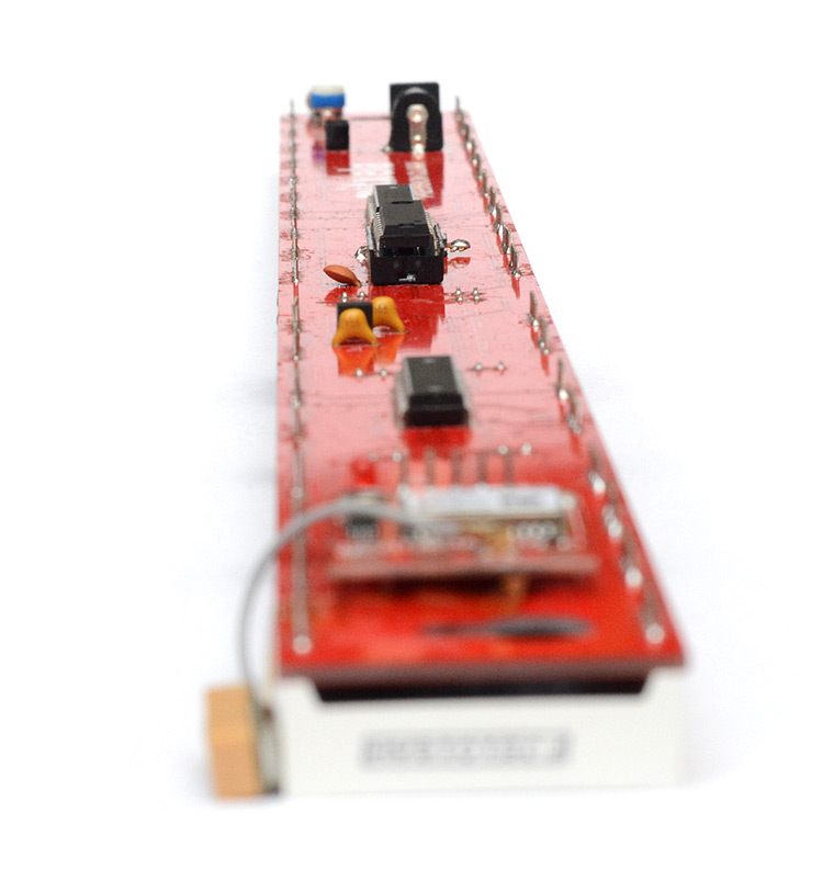
Seen here superglued onto the end of MkII.
It sorta worked. One problem is I forgot to check the Hfe of the transistor before soldering it in place (underneath the main micro). I think it's probably about 150. The effect is that when it's bright, the extra digit is brighter than the rest of the digits, and when it's dark, the extra digit is dimmer than the rest. The correct thing to do would have been designing a circuit which didn't depend on an exact value for the transistor gain. With an op-amp we could have constructed an adjustable current amplifier in order to accurately match the performance of the LED display drivers. A more realistic solution (in terms of effort) would have been to root through the bag of transistors and sort them all by their Hfe and pick the one that's closest.
To conclude this extra-digit adventure, we are left not entirely sure if it's ticking correctly. Filming it at 1000FPS is inconclusive, because the digit changes don't line up with the frame boundaries (sadly this particular camera insists on a fixed shutter speed of 1/1000th of a second when shooting at 1000FPS), and the footage bleeds together. The correct course of action at this point is to buy a 10,000FPS camera.
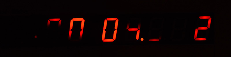
A single shot at 1/1000th of a second, you can see the partially illuminated matrixed part of the display, and in this case the extended digit is switching between 7 and 8.

You may notice that the matrixed section appears brighter than the extra digit, even though at the light levels in the shot above all digits appear the same brightness. This is because the matrixed digits are only illuminated for part of the time, and to a human eye it all averages out.
At 1/4000th of a second we can see even less of the main display, but at least now the extended digit is clear.
I think it might be possible to get clear footage with the 1000FPS camera by reducing the duty cycle on the extra digit: display the digit for 0.5ms, then blank the digit for 0.5ms, and so on. With that, there would be a reasonable chance of the 1ms frames only lining up with one of the displayed digits, and it should be possible to get clear footage without synchronization by just trying repeatedly.
Github
That about concludes this rather lengthy and meandering writeup. The updated source code to the clock was pushed to the existing Precision Clock Mk II repo. The board layout has been pushed to a new repo here.If you would like to buy one of these kits, visit mitxela.com/shop.
Updates
(2019): Since writing this page, the board has gone through a few minor changes. They're explained in the commit messages if you want more detail, but in short:
- Widened the TO-92 footprints to make them easier to solder
- Removed the ground plane around the GPS module to investigate if that had an effect on the GPS reception. It's very difficult to keep the other variables constant here, not least because the reception depends on the weather and whether your neighbours have their TV on. Conclusion was that removing the ground plane didn't help, so I added it back in again.
- Made the linear regulator optional. All the GPS units are 5V compatible now, so it's a bit pointless. But I kept the footprint there, if it needs to be fitted just cut the trace between its legs.
- Added more capacitor footprints
- Added an optional crystal footprint for the ATtiny
What's next? I have an idea of how to improve the reliability of the clock by fitting a temperature-compensated oscillator, and then only listening to the GPS signal if it has a fix. Part of the problem with the current setup, after a fix is lost, is that the oscillators of the ATtiny and the GPS module drift apart. If we chose to ignore the GPS except for when it's completely accurate, the display would be more stable. Rather than make a new PCB, this could simply be placed on a daughterboard that attaches to the existing clock.
Another way to keep them in sync would be to upgrade the GPS module to one of the dedicated timekeeping ones. Most of those have a configurable frequency output, which could either be used to clock the ATtiny directly, or fed into its T1 pin to drive the centiseconds.
For Precision Clock Mk IV, I have an overhaul in mind. Get rid of the display drivers, and get rid of the matrix. There are microcontrollers with a high number of I/O pins, which could allow us to drive every digit independently. The goal would be to have a flicker-free display for video footage at beyond 1000FPS. Not sure if there's any demand for such a clock, but it would be fun to develop!