Precision Clock Mk II
28 Sep 2015Progress: Complete
Note: This page is about the second Precision Clock I built. See also the mark I, the mark II½, and the mark IV.
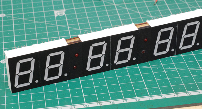
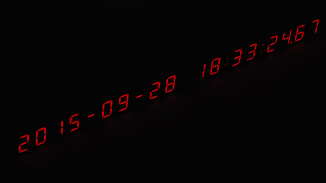
Precision Clock Mk I did pretty well. In fact I feel almost depressed about how reliable it is: when you think about it, it's actuated a hundred times a second, non-stop for the last three months and shows no sign of wear. I wish I could build something mechanical as durable as that. But it had its flaws, first of which being the cheap quartz RTC that needs to be set. It also consistently gained time, several seconds a day. I figured that perhaps the crystal that came with the DS1302 module wasn't matched to the chip, since it has internal 6pF capacitors, but the 32.768kHz crystals sometimes come intended for 12pF. Adding an extra 6pF on each leg improved the time greatly but it still gained about one second a day. Maybe more capacitance? Perhaps a trimmer cap. Or a better, temperature-compensated clock module? Nah, if it has to be set manually, it'll never be accurate enough.Mark II is bigger and better. These are 1-inch-tall digits which cost twice as much as the last lot ( 20p each! Blimey). Individual digits means it's much easier to wire up the hyphens of the date (which I left out of Mark I) in place of the decimal points of other digits driven by the max7219. I also made proper colons between hours, minutes and seconds. They were laser cut bits of plywood, not because I needed the accuracy, but just because I have a laser cutter and it's a thousand times faster than laying it out by hand.
Painted black and with 3mm LEDs it certainly looks the part.
I wired up the first half in the same way as before, with individual wires stripped and soldered for every connection. Took ages.
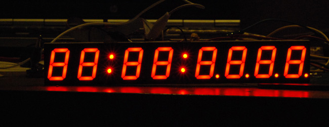
The max7219 chip drives them with constant current, and apart from oblique angles the colons looked too bright. Later on, I rewired them to be driven in parallel to halve the current.
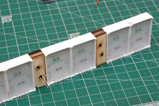
When it came to making the second half, I had the bright idea of using some enamelled wire pulled from an electric motor. There are different kinds of enamelled wire, I learned, but the second motor I tried had the right kind of stuff. A bit thin, perhaps, but the point is its enamel coating will melt and burn away at about 400°C. This means you can just wrap it around each leg and solder away, much faster. I doubled it up just in case the thickness was an issue.
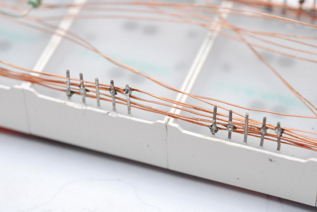
This worked remarkably well and took substantially less time to do.
So, that was the easy bit over. Now back to the timekeeping.
Radio controlled clocks use the 60kHz signal that in this country is broadcast by the NPL. Since this is what wall clocks do, I assumed it was the best way of getting the time. But. You can pick up the time code from GPS. And suddenly I realized there were so many advantages to doing this:
• It's broadcast in the GHz so the antenna is physically smaller
• GPS modules are actually cheaper than the inductor/decoder to pick up the 60kHz signal - £7.50 as opposed to £12
• From a warm start, GPS can get a fix in under a second, 60kHz signal takes at least full a minute
• UART output of cheap GPS modules is very easy to read
• Not that this would ever be noticed by a human, but the GPS time is compensated for the speed-of-light delay. I'm a few hundred miles from Anthorn so the time signal here is what, 2 milliseconds slow? Still, nice to know.
Excellent stuff, and the GPS module is physically small enough to comfortably sit on the back of the LED displays. It didn't take long to get a rudimentary clock working.
There's a myriad different configurations for the module I got, a NEO6MV2. There's actually a 6T version designed for timekeeping but it was dearer. Since configuration is stored on its battery-backed ram, I thought it easiest to just go with the default config from a cold start. This means it outputs, about once a second, a string of NMEA messages at 9600 baud, 8n1. Among these messages is $GPRMC, the recommended minimum data, which tells you the time, date, long/lat/speed/bearing etc. Another useful message is $GPGSV, for satellites in view.
Although it displays the milliseconds, it's only updating them once a second. Interpolation will be needed. But before we go there, an issue arose that hadn't occurred to me: daylight saving time. The module only spits out UTC.
So, to correct for it, the clock needed to a) work out the dates that British Summer Time starts and ends, which is different every year; b) work out if the current date is within those dates; c) add an hour, which means changing the date if we're past 2300 hours.
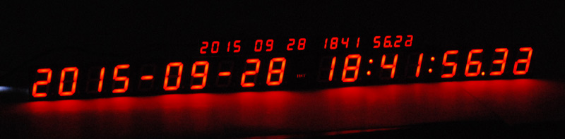
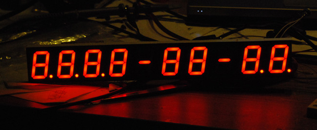
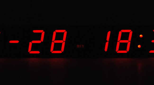
I will admit that coding all of that from scratch in assembler was a bit tedious. I distracted myself by thinking about what should go between the time and date. For a UTC timestamp, it should be a capital T, but that'd be difficult with a seven-segment display. I decided instead to go with this:
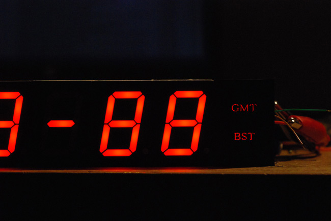
GMT / BST will light up as needed. The letters were laser cut into another bit of plywood that I had fitted acrylic windows to and painted black. The laser removed the paint where needed. The effect isn't quite as good as I'd hoped since the viewing angle is very poor, but I think I can improve it by dribbling some varnish into the etched acrylic to act as a light distributor.
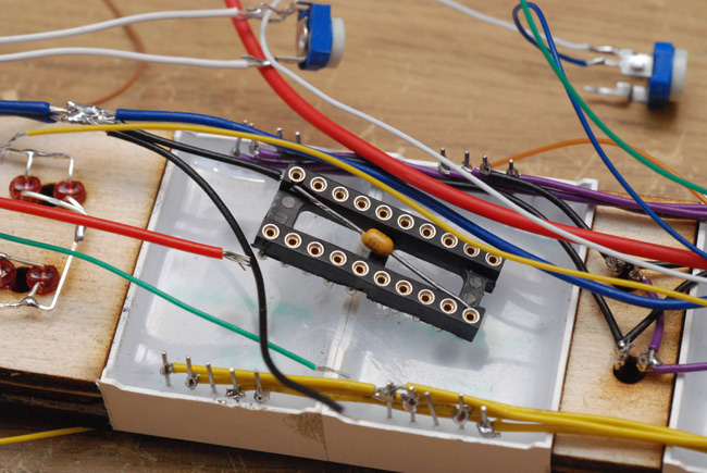
The chip I used to control it all is an ATtiny2313, and I socketed it just because I'd salvaged these cool sockets with embedded filter caps.
So. We get a bunch of NMEA messages, strip the time and date out of them. A 100HZ interrupt increments the centiseconds, and this needs coding so as to overflow properly, even midnight on the 31st of December, or 28th of Feb. The time code is given to the millisecond. I built and coded the clock knowing that the strings came out something like this:
$GPGGA,140408.558,,,,,0,0,,,M,,M,,*49
$GPGSA,A,1,,,,,,,,,,,,,,,*1E
$GPGSV,1,1,00*79
$GPRMC,140408.558,V,,,,,0.00,0.00,210915,,,N*42
That message was before it found any satellites (0 in view). I don't know if it was internally keeping time or if it briefly picked up and then lost a signal. From a completely cold start (off for many days) it took many minutes before it successfully got the date. Soon it finds a couple of satellites.
$GPGGA,141348.300,,,,,0,0,,,M,,M,,*40
$GPGSA,A,1,,,,,,,,,,,,,,,*1E
$GPGSV,1,1,02,27,,,25,08,,,27*74
$GPRMC,141348.300,V,,,,,0.00,0.00,210915,,,N*4B
When it gets to four satellites, it has a fix, and will fill in all those blanks with data. Once it has found a fix, it will find it again almost instantly if it's been off for less than 4 hours. That's a hot start. What I forgot to think about was when it's been on for a while, even indoors on my shelf, it's quite possible for it to find lots of satellites, and that satellites-in-view message expands to multiple pages. u-blox, who make the module, have a piece of software "u-center" which decodes all this data and plots where the satellites are in the sky.
But there's a problem. Having written my interpolation nicely, I watched the clock as BBC Radio 4 beeped the hour, and disappointingly found the clock to be over half a second slow. And I put it on a window sill to get more satellites, be sure it had a fix, and it got worse. It took some thinking to realize that of course, the baud rate is 9600, that's over 1 millisecond per byte, and the NMEA messages were now over 400 bytes. How annoying.
I solved this issue by using the timepulse from the module. The data sheet had said that the configurable timepulse was only available on the 6T module, but a 1PPS output is actually output on all of their modules. I hadn't found it when I scoped, because it's only output if it has a definite fix. Then, the rising edge is aligned with the 000 millisecond mark.
Had I known this earlier, the interpolation code could have been a little simpler, but at least it's easy to add this. The INT0 interrupt is just two instructions, to set the deciseconds and centiseconds to 99, which then falls through into the timer interrupt that immediately overflows it to the full second. Then, at the half second mark, the NMEA message finishes and the full date and time are synced, ignoring the millisecond data. Easy, excellent, and listening to the beeps on Radio 4 it aligns perfectly.
Back to the hardware, I went to the effort of making a current mirror circuit and a single LDR to do the auto-dimming. This is, after all, just two transistors and means that the entire display is always at the same brightness. The minimum brightness, in absolute darkness, was actually too dim to read, so I slightly brightened it by placing a 10 megaohm resistor in parallel with the LDR. I didn't have that problem with Mark I, so maybe it's to do with the voltage drop across the transistors. The max brightness is set by a trimpot, about 20K. The LDR itself is now facing sideways at the leftmost of the display, instead of upwards like before. This means it doesn't overreact to the spotlights over my desk. Overall the auto-dimming is very successful.
Possibly the BST/GMT lights could be a little brighter. To even them out I'd used two LEDs in parallel side by side, but maybe that was a mistake. Or maybe not, they should be at least as bright as the colons. Perhaps the acrylic was too thick. Then again, we don't want it to be too distracting, so I spose slightly dimmer than the rest is ok.
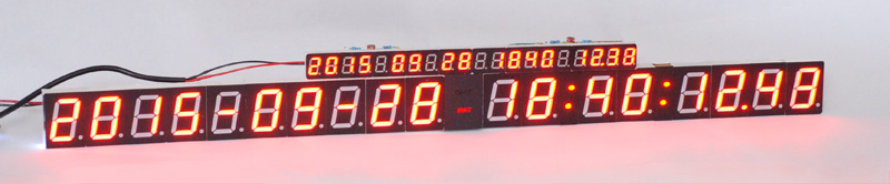
Now for a comparison with Mark I...
One last question is if, and at what frequency, the colons should flash. Once per second felt too fast, so I settled for once every two seconds, slightly staggered with each other. Perhaps they could in some subtle way indicate how many satellites it has in view. Hmm.
I could even add a button or two to cycle through the rest of the GPS data. May be useful, perhaps. There's also a jumper on the back to disable the auto daylight saving time, in case the rules ever change on that.
The back of the clock is nowhere near as neat or interesting as for Mark I. Click for full res.
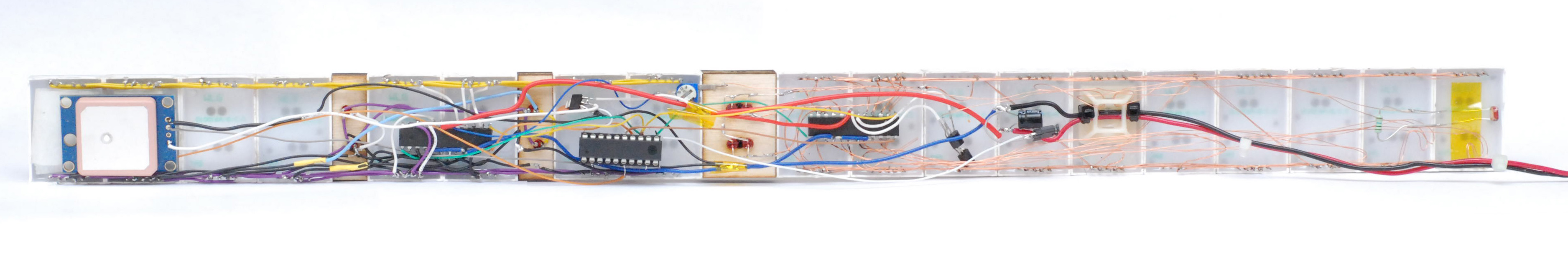
From left to right: GPS module with the brown timepulse wire soldered directly to pin 3 of the chip, first MAX7219 chip in a tangle of wire, 3.3V regulator just above the ATtiny2313, then the brightness adjust trimmer, slightly tidier wiring around the second MAX7219, the two PNP transistors for the current mirror, reservoir cap and the GMT jumper which has fallen out of where I squished it, cable clip for the power leads, and finally the light sensor with 10M resistor. I may go over all that again with some tweezers and glue now that it's finished, since it certainly could be a lot neater. And/or add a rear cover, since it isn't particularly pretty.
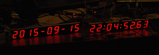
In conclusion, I now have a clock that is precise to the centisecond and accurate to beyond the centisecond, or if it cannot get a GPS fix, accurate to within a second. Autodimming brightness levels, no need to set anything, and hopefully should function for the next 85 years. The code will break at the year 2100. People would be disappointed if it didn't.