
Precision Clock Acrylic Case
29 Oct 2025Progress: Complete
An acrylic case for the Precision Clock Mk IV. Perhaps this isn't worthy of its own project page and would be better served as an addendum, hidden away in the depths. But it's a while since I've posted anything. The last few months have been spent trying to organise production of more clock kits, which is great, I'm delighted that it's popular, but I ran into so many tedious problems and delays that it (almost) doesn't seem worth it.
In an attempt to take my mind off of things, I figured I'd build another bespoke clock. In truth I've done this a few times, throughout the chip shortage I entertained myself by building, amongst other things, comically large precision clocks which have yet to be published.
To be clear, if all you want to do is increase the contrast of the 7-segment displays, the easiest way is to fit a red lighting gel over the face of the clock.
From a distance this looks great, and if you're careful you can tape it in place such that the hinge still works.
It's difficult to capture on camera, especially under the studio lights, but you can take my word for it that there's a marked increase in contrast, for comparatively little effort. However, up close, it does just look like you've taped a lighting gel over it.
Plenty of people have built nice cases for their Precision Clocks. I keep reminding myself to set up some kind of gallery of them. A few enthusiasts have built some really nice wooden cases for their clocks, but perhaps my personal favourite is the work of Just Andersen, with this design inspired by the Roku Soundbridge 1000:
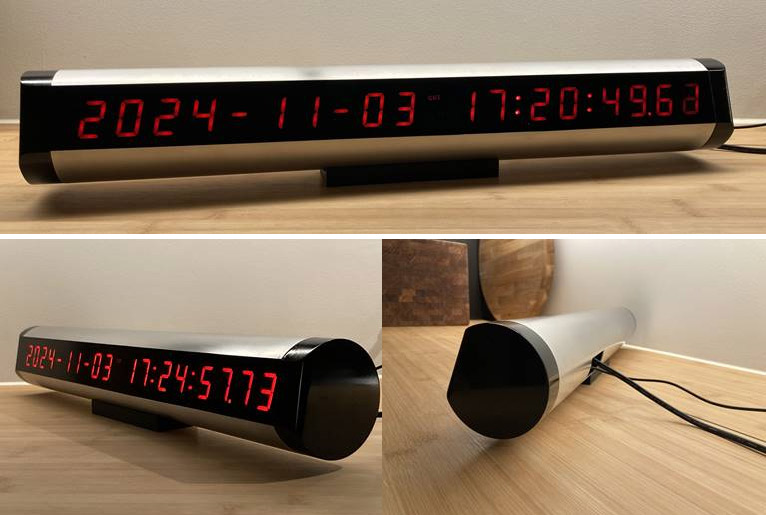
That's an 80mm diameter aluminium tube, with delrin endcaps and smoked acrylic window. Gosh it looks good!
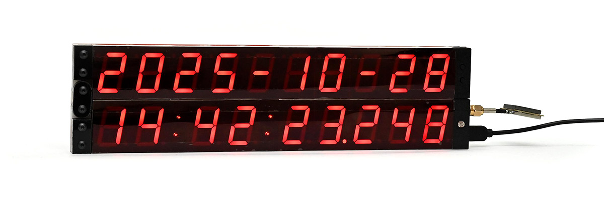
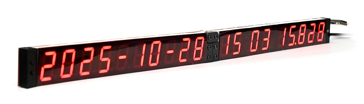
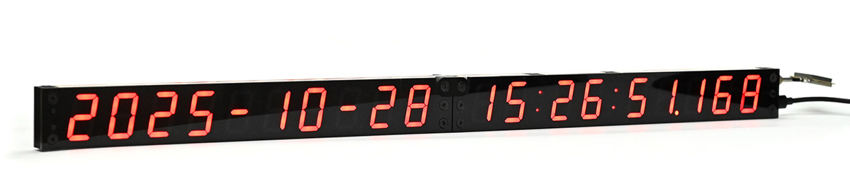
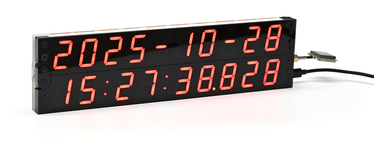
With the release of the Mk IV, I've already received a few pictures of nice cases built for it, but all of them, by necessity, lock the clock in a fixed orientation. A key feature of the Mk IV is that it can fold in half like a clapperboard, and unfold to give us the full aesthetic of an ISO timestamp. Idly I wondered if it were possible to build a smoked acrylic cover for the clock that still lets it be reconfigured, to augment the articulated joint rather than hinder it.
Soon a plan began to form.
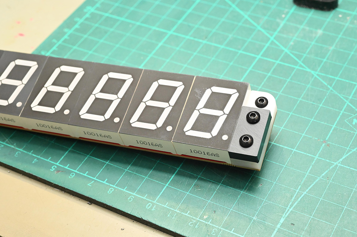
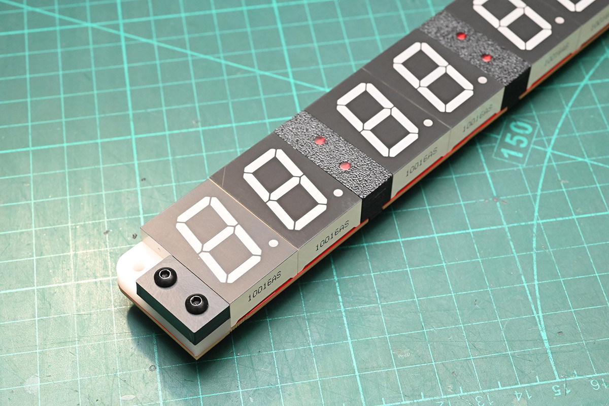
I started by sanding some of the laser cut hinge pieces.
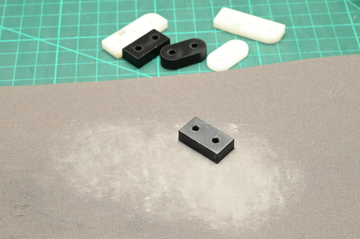
The correct technique is to lay the paper on a flat surface (ideally a surface plate or piece of glass) and rub the part against it. With the current supply of 7-segment displays, the stackup of the hinge parts ends up slightly proud of the top surface, so I needed to shave off half a millimetre to get it flush. It's not much to remove but even on this relatively coarse 400 grit paper it takes a while. Intermittently we can check the progress.
Hmm. The matt texture is quite appealing. Compared to the raw laser-cut surface, which is a mix of shiny and melty, a quick sanding seems like a worthwhile upgrade even for a regular clock assembly. I might have to add that to the instructions.
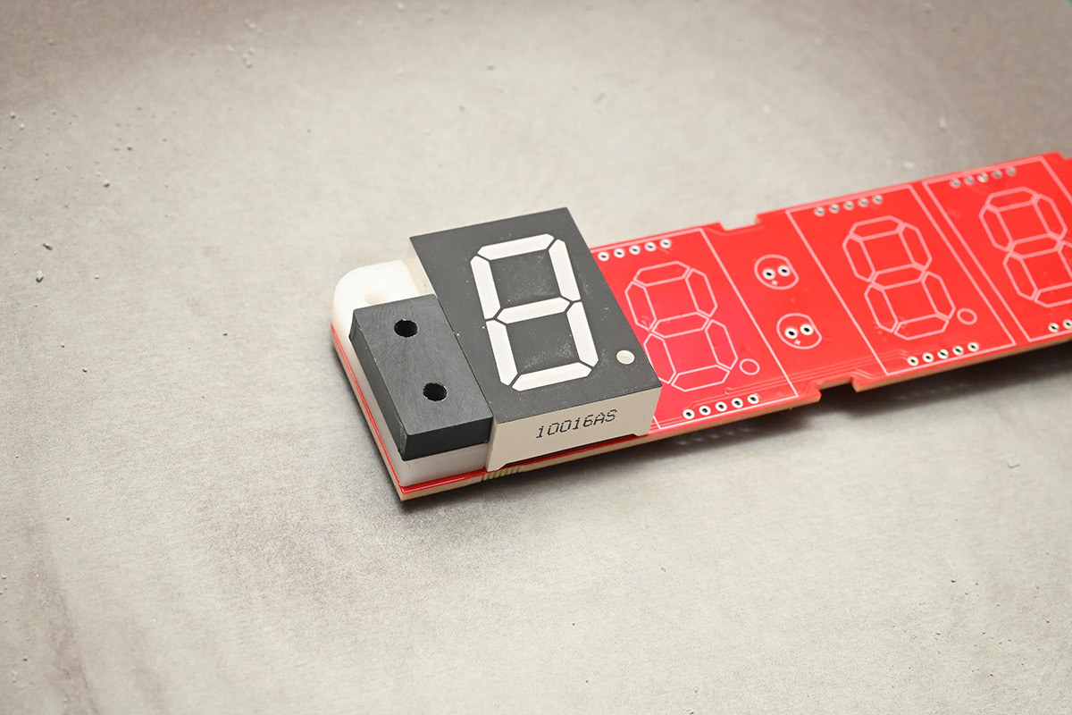
The hinge design relies on the digits to act as an end-stop, and different manufacturers of digits have slightly different plastic mouldings, so it's critical to assemble the hinge part first, then squeeze the adjacent digit up to it. It's a shortcoming of the clock design which only became apparent much later. So, to assemble this bespoke clock, I did a temporary hinge assembly to hold the digits, which will be undone after they're soldered.
Also notice the protective films have been peeled off. Normally I suggest leaving them on, trimming any excess, but here we won't need the protection. I'd forgotten how susceptible the bare surface is to fingerprints. The finish comes off easily if you scrub it, and smears horribly if it comes into contact with IPA or flux cleaner.
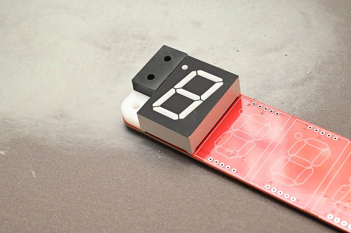
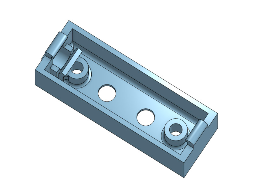
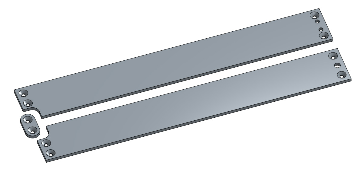
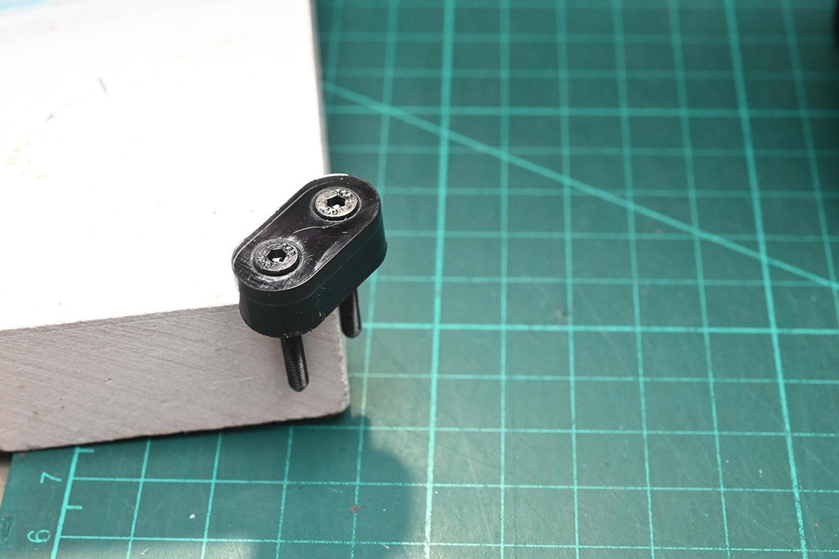
I dreamt up some alternative 3D printed parts, with additional holes that can be tapped for M3 bolts. Between this and the hinge pieces, we should be able to securely hold our acrylic cover. With the internal structure that holds the magnet, it was trickier than expected to squeeze these in, in a way that didn't foul the switches.
I acquired some longer switches: 15mm tall instead of 12mm.
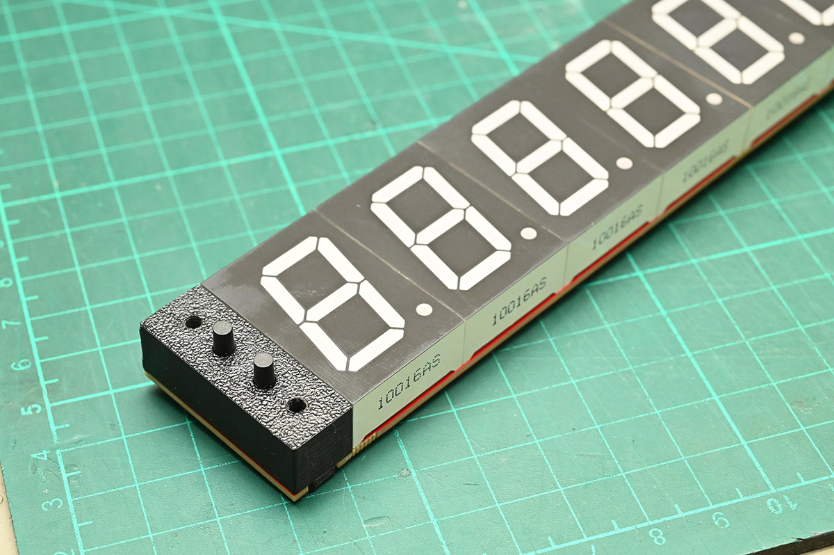
The part number for the original switches was TS02-66-120-BK-160-LCR-D, where the 120 indicates the length, so a 15mm version would be TS02-66-150-BK-160-LCR-D. In my impatience to build this, instead I grabbed some random 15mm switches which turned out to have a higher actuation force. Once upon a time, I did some experiments with different switches and decided 160g was the most satisfying for the clock. Perhaps I'll order the correct ones and swap them out later.
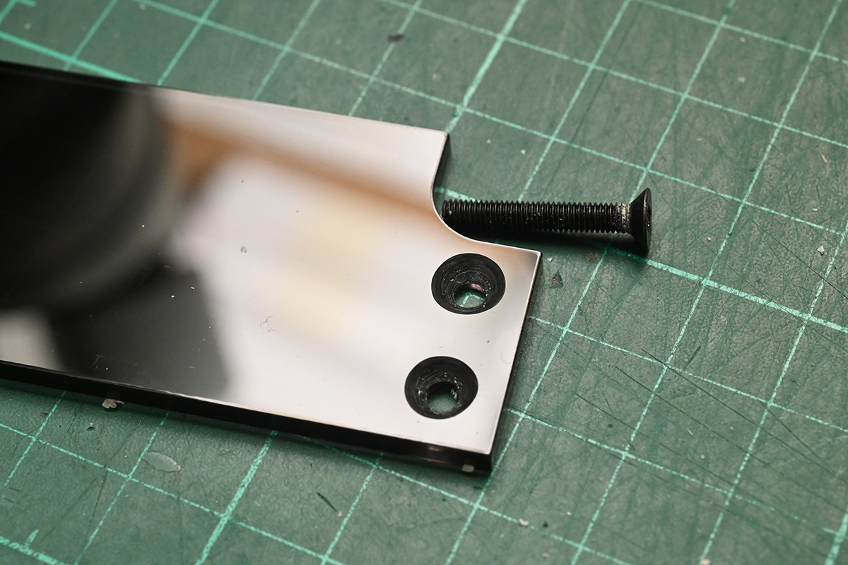
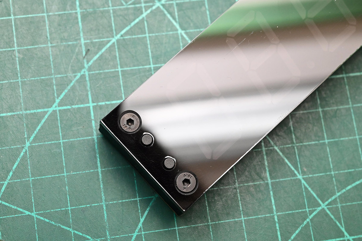
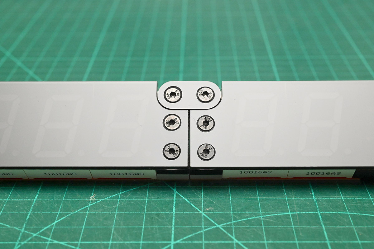
A minor bother with the Mk IV clock is that the bolt heads protrude out from the face. For this bespoke cover, I think we can figure out how to get them flush.
Acrylic cuts beautifully with the laser, but those countersinks will have to be performed by hand. I grabbed a brand new countersink tool and lubricated the bit with beeswax.
To compensate for the kerf of the laser, I cut a part, measured its real dimensions, offset the design and then cut the part again. It conveniently leaves us with these test bits to practice on.
The cut edge has a bit of a wobble on the part on the right, due to the lacklustre belt tension on this ageing machine. Dropping the cut speed (and power) fixes it; the part on the left is basically perfect.
Applying the kerf offset to the whole design, we can then cut out the real deal, and very carefully sink some counters.
I think, were I to do this more than once, I'd set up a drill press with a depth stop, rather than eyeballing it with the handheld drill.
Hey – this doesn't look too bad. Not too bad at all.
Now for more sanding...
...and assembling the time side of the clock using temporary bolts on the hinge.
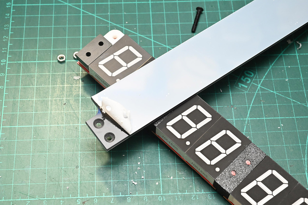
We then disassemble the hinge, and fit our countersunk smoked acrylic cover over the top.
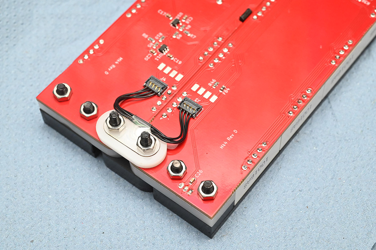
As part of the update to Revision D of the PCB, I controversially replaced the LDR with a phototransistor. I've bitten my nails about the decision ever since. The fact is, LDRs simply make the best light sensor, but they're technically illegal at least in Europe because they contain cadmium. I eventually found a nice phototransistor that behaves almost as well, and has the form factor of a flat-top LED.
One unexpected bonus of the new light sensor is that it fits perfectly into a 5mm hole, compared to the awkward, inconsistent oval of an LDR.
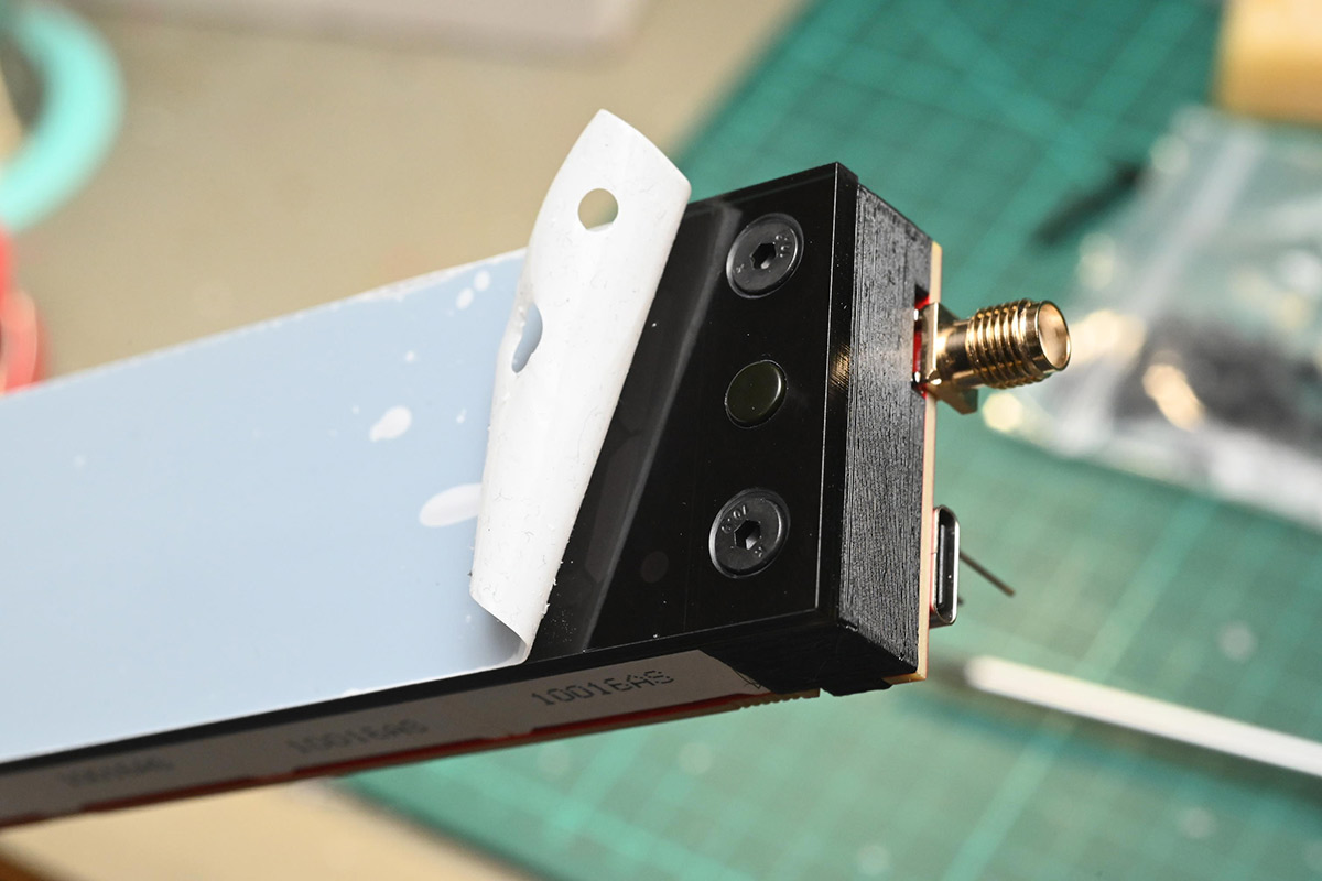
I ordered the short countersunk bolts especially. If one were trying to retrofit this cover to an existing clock, you'd need to unsolder the light sensor and extend its legs. Probably easiest to just buy a fresh one.
Another update to Revision D of the PCB is that it now has a USB-C port. I was somewhat taken aback by people's disparaging reaction to the micro-USB. Back when I designed the clock, pre-pandemic, I did a spot survey on what USB socket to give it and the majority of responses favoured micro-USB. Opinions have changed since then. Probably would have been less embarrassing if I hadn't waited so many years before releasing it. Anyway, changing the socket was trivial.
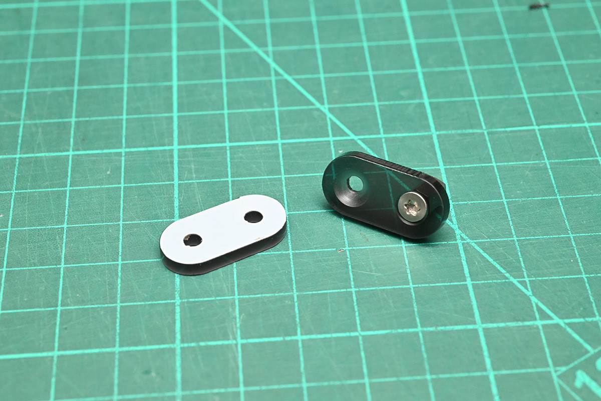
Finally we sand the hinge linkage, adding the countersunk acrylic on top, with a nice greasy thumbprint.
Right before countersinking, I had a mind to turn this part upside down. The laser kerf is conical, and flipping one part is a way to make them mate more closely. This is pretty thin material though (3mm) so it's probably unimportant, and if we're worrying about tiny visual differences, the underside of the cut edge may not match the top.
I had to use 25mm bolts for the hinge assembly, the ideal length would have been about 21mm but it didn't seem worth cutting them down. To assemble the hinge, a layer of paper towel helps us avoid scratching the face.
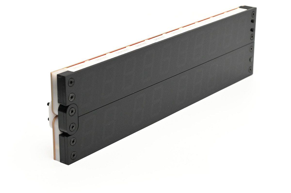
An immediate bonus is that the acrylic bolsters the end points of the hinge action, instead of relying on the digits and delrin. Actuating it is noticeably nicer than before.
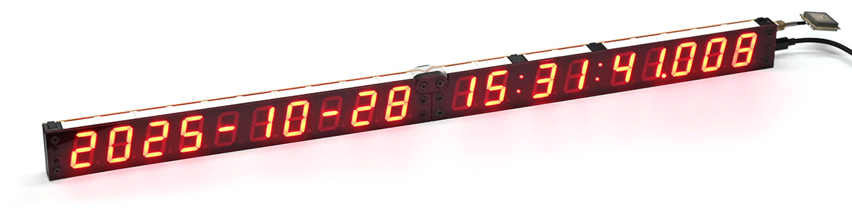
Hot damn. It does look good. Annoyingly so – now I am looking at the unmodified clocks with distaste.
Oh dear, am I going to have to change the kit and the instructions, to make this smoked acrylic cover the default?
The additional thickness also makes it more stable on the desk. At least in the folded position, it's less likely to get knocked over.
About the only downside is that the maximum brightness has dropped a fair amount. Whether that's actually an issue depends on the use-case, outside of high-speed photography it probably doesn't matter. Even in a brightly lit outdoor scenario, the boost in contrast is probably worth it.
There are different grades of smoked acrylic: I went for the darkest one, to get the most effect, but perhaps a lighter shade would offer a compromise. Another option is to use translucent red acrylic, and get something more like what we had with the lighting gel. To see how this looked, I built yet another clock, exactly the same design as before, but in deep red tinted acrylic.
Honestly it doesn't look nearly as good, but it is a lot brighter than the smoked version. It is however very hard to convey the effect on camera. For a fairer comparison, I took three clocks outside and snapped them next to each other.
In the middle we have an unmodified clock, at the rear is the smoked acrylic, and at the front is the red tint.
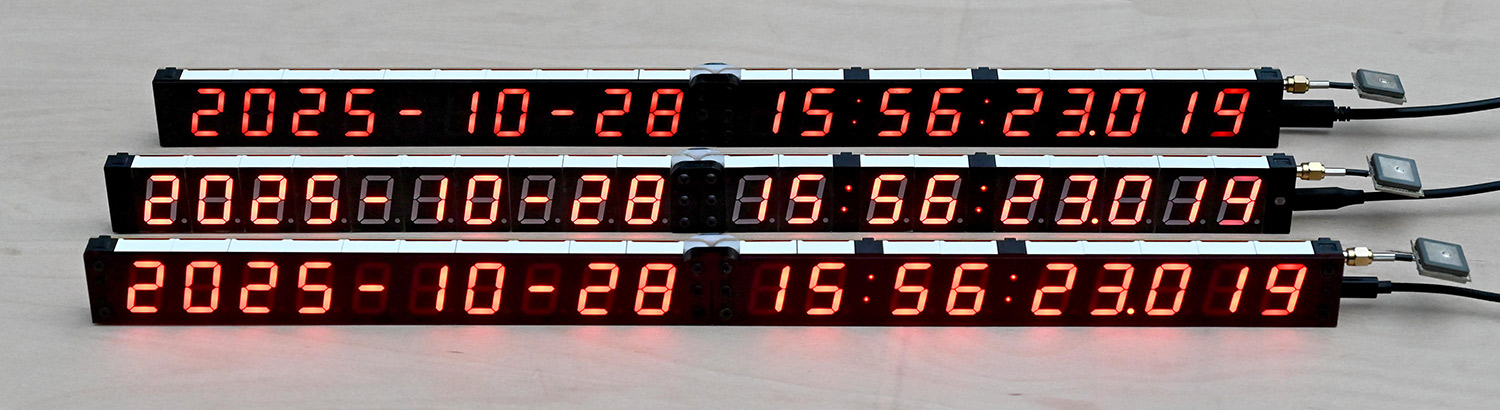
The last digit is part-way between 3 and 4.
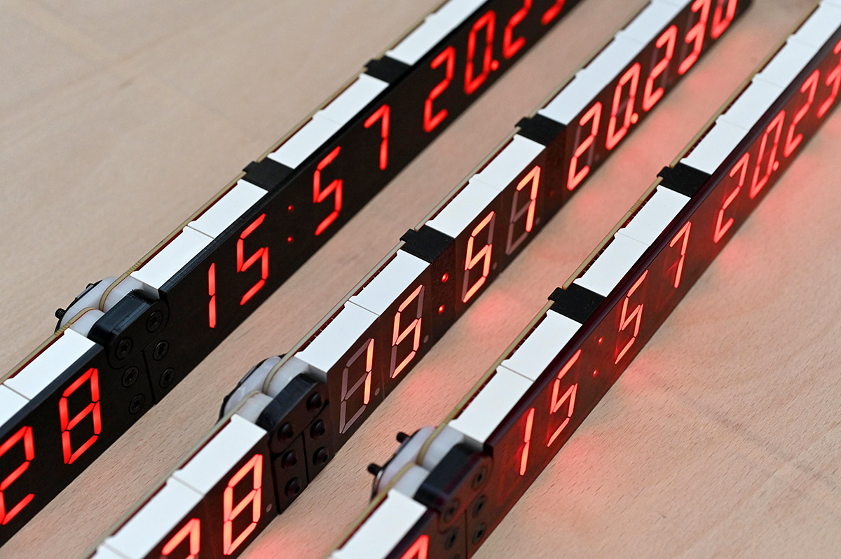
The unmodified clock definitely still holds the edge in terms of brightness, with the red tint in a close second.
I would have also brought out the one with taped lighting gel too, but I was running short on USB batteries to run them.
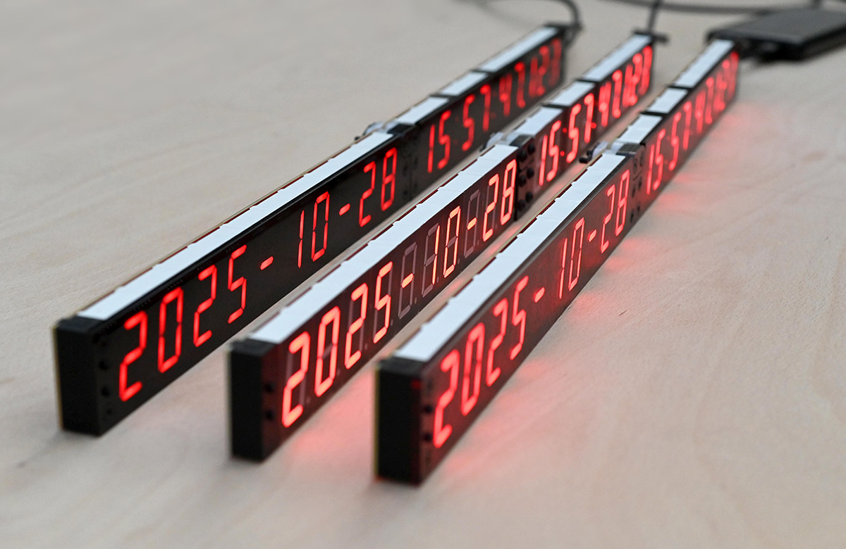
I think smoked is the clear winner though.
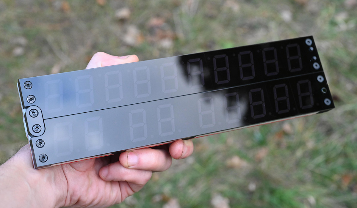
It's hard to convey just how much the shiny black surface enhances the look and feel of the clock.
Conclusion
I dreaded posting this, because I don't want to devalue the existing clock offering. But you gotta admit this is a neat upgrade.I think for most people, either the lighting gel, or a case that fixes the orientation, are probably good enough. Nobody needs this swish upgrade. I'm already struggling enough to source the parts for the clock kit, so adding more parts, or offering an upgraded version just sounds like more stress for me.
Annoyingly, it's not that easy to take an assembled Mk IV clock and upgrade it later, as it requires desoldering the switches and the light sensor, replacing or extending the legs of the light sensor, new 3D printed parts, and more bolts. One might be able to get away with just drilling holes in the existing 3D prints.
For now, I've chucked the relevant design files in the cad folder of the repo. Tools required are a nice sharp countersink bit, an M3 tap, and sandpaper. In addition to laser cutting and 3D printing, you'll need new switches with a 15mm actuator height, and countersunk M3 bolts (2 x 25mm, 4 x 20mm, 4 x 6mm). If you're adapting a Revision C clock, you may want to adjust the hole for the light sensor before lasercutting.