Precision Clock
7 Jun 2015Progress: Complete
Note: This page is about the very first Precision Clock I built. See also the mark II, the mark II½, and the mark IV.
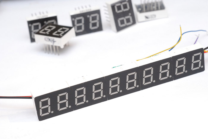
I had a dream when I was very little about LED 7-segment displays. I dreamt that I had many, many of them and that they did interesting things. I wanted an enormous calculator with a ludicrous number of decimal places. There is something enticing about that red glow. This dream was pretty much forgotten about until the other day, when all of a sudden it dawned on me that 7-segment displays are no longer the impossibly expensive items childhood me perceived them as. In fact they're impossibly cheap - 20 digits for £2 including shipping. Hoorah!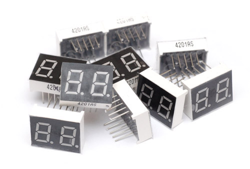
Now I probably should have put more thought into this before ordering them. I figured I'd build a very precise clock, and that being in pairs like that would work well, letting me put a space between day/month/year and so on. Groups of four are available, some even have colon markings for clocks. This would have saved me some wiring time, since when these actually arrived I decided to ditch whatever layout I'd planned and stick them all together into an enormous row.
I considered turning a group upside down to get a colon but I didn't like the look of it.
To drive the displays I'd ordered some MAX7219 chips. These are shift registers/LED matrixers specifically designed for this sort of thing, they'll even decode BCD to the correct segments. Amazingly, including shipping, I got five for £1.46. Each will drive 64 LEDs, or eight digits. A date/time code to the precision that I want (YYYY-MM-DD HH:MM:SS.SS) would fit nicely into sixteen digits. I felt like there was nothing to lose by leaving unconnected digits in between to space it into the 20 digits available. This'd be ten digits under each MAX7219. Had I ordered single digits, I could have wired it so that the control of the decimal point of some numbers, like the year, would be used to control the hyphens of the digits inbetween the year and date. But I was getting impatient and just ploughed ahead.
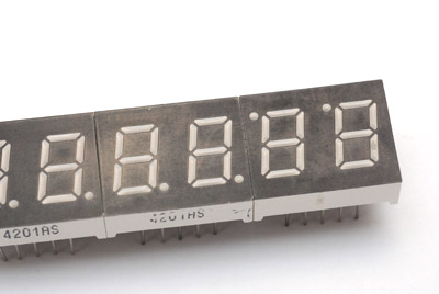
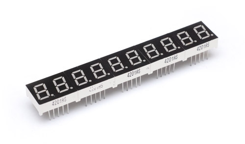
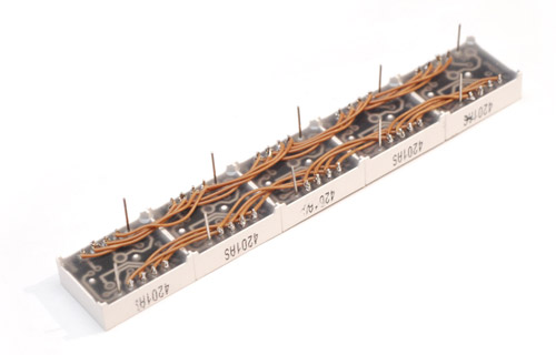
Superglue was used to stick them into groups of ten.
Guess we better start by wiring all the anodes together.
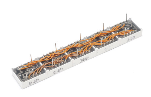
Cathodes yet to be trimmed. Next I cut the legs real short on the MAX7219 and soldered some power wires in place. These'll run through the middle underneath the chip. 128 LEDs, each consuming ~10mA, we could see more than an amp running through here. Unlikely that they'll all be on at the same time though, and I'll probably be dimming them somewhat.
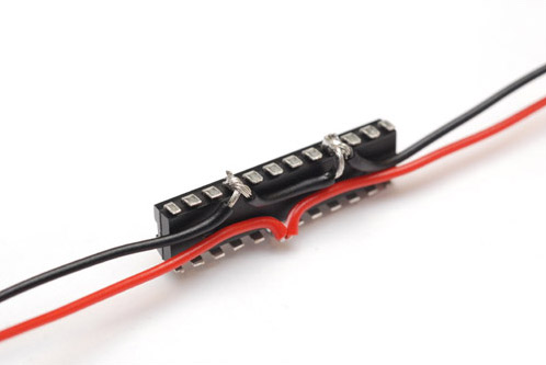
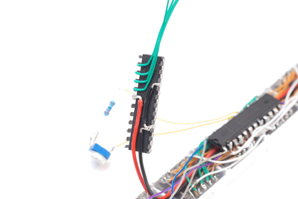
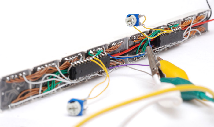
Commence fiddly wiring. Greens are the anodes for each segment, whites are the cathodes for each digit. Blue, purple, grey are the serial control and the yellow lines are to a resistor which controls the display brightness. Brightness can also be set digitally, changing the scanning duty cycle. The data sheet explains this pretty well.
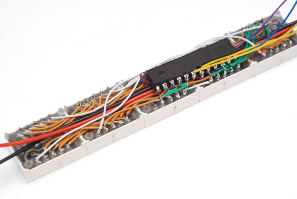
All pretty well concealed on the back - very neat.
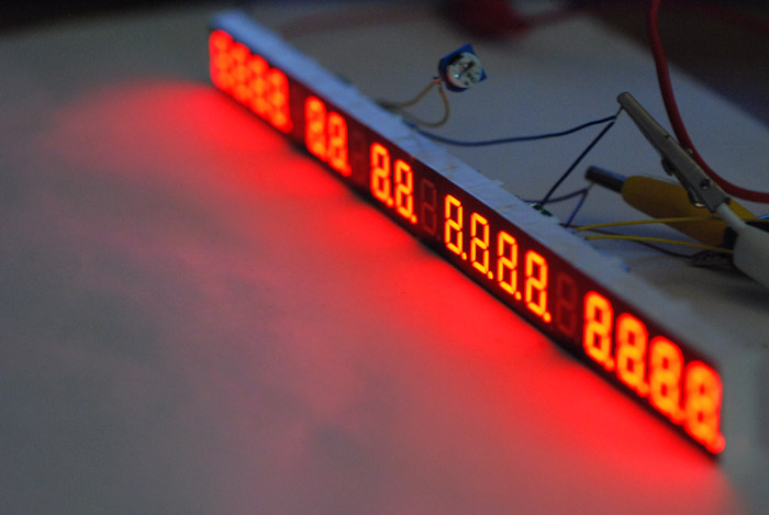
Couldn't resist wiring it up to test at this point. Quite satisfying really. Display test turns all the lights on...
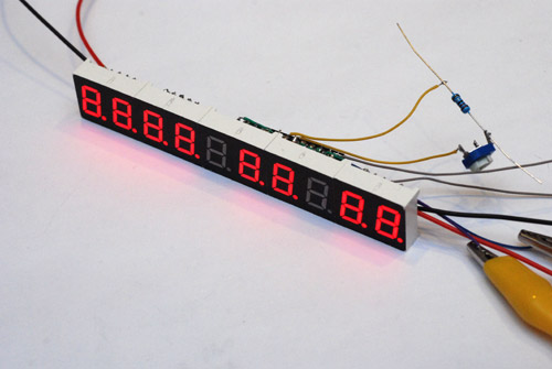
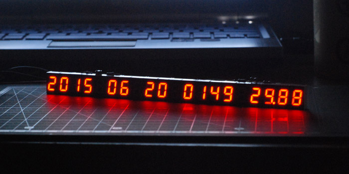
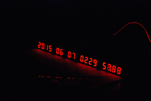
... and here's how the date will look on it. It's hard to capture the glowy redness under a camera flash.
OK. Now rinse and repeat for the other side.
Once you get into a rhythm, it doesn't take all that long. Only a few hours. But seriously, this side was quicker, as I had foresight on my side. No more trying to shove wires underneath the chip after it's stuck down.
It's starting to remind me of the high-density wiring you see on satellites and particle accelerators from the 1970s. A little.
It's getting exciting now.
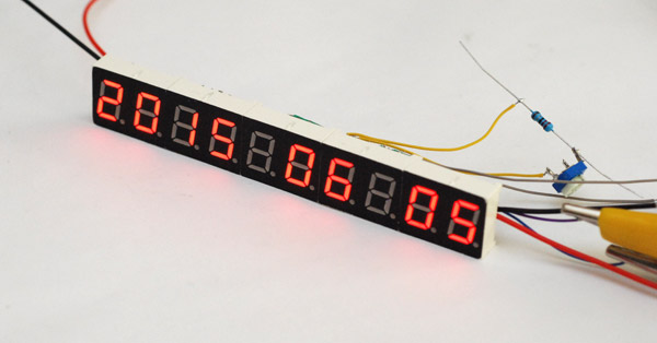
And some quick coding later, we have a working clock. I'm not sure whether to display (or flash) the decimal point between hours and minutes. You can tell it's ticking since the last few digits have blurred together on this half-second exposure. Minimum brightness with the room lights off. Centiseconds is the perfect resolution, I think: fast enough to be unreadable, but slow enough to see it flickering. Yes, this picture was taken at half past two in the morning after a wild Friday night with a soldering iron.
Delicious, but we're far from done. I am slightly regretting those blank digits which mean the display can only be used as a clock. I may have to order more, to make best use of the MAX7219s I have left over. In the mean time we have to consider practicalities. The display is currently controlled by an ATtiny85 with an 8MHz crystal as that was all I had. I used a timer with a prescaler of 32 and an output compare value of 250 (or 249 from zero) to give a 1kHz interrupt and then some simple bitbanged serial data as I find it's usually quicker for this sort of thing than trying to work out what all the control registers do for the universal-serial-interface.
To be a clock, we need to keep time, and the 8MHz seems to have stayed reasonably accurate over the one day of testing so far, but ideally we shouldn't have to set the time on power-up. Standard practice is to use a DS1302 or similar real-time-clock module (I've ordered one, 99p including shipping) which has a battery backup. You just talk to it when you want the time and date and it gives it to you. But we still then need to initially input the time, so some kind of control panel will be required. I am thinking of tactile switches, with a resistor ladder going to an analog input. We are, however, running out of pins on the attiny85 and may have to upgrade. Remember that the 8MHz crystal takes up two, and the serial bus takes three. We can probably use the same pins to talk to the display as to the clock module, possibly even the chip select pin too, as the DS1302 is active high and the max7219 is active low.
Another concern is display brightness. We can make a fully analog control using the resistors, but we need one for each half of the display. Possibly a transistor current-mirror circuit could make one pot control both. If we fit a switch array, simple up/down brightness buttons would be trivial. If an analog input is available, we can use a light sensor to do the dimming automatically. In fact, if we didn't want an override for automatic dimming, it may be possible to use a purely analogue solution, wiring an LDR straight to the reference pins of the MAX7219. I shall have to try it.
I'm more concerned right now about setting the time and date automatically. Obviously a desirable solution is to pick up the 60kHz atomic clock signal. You can get a radio module designed for this for about £12 but that moves this silly project into actual money territory. It would be cheaper to get an ESP8266 and pick the time code up over wifi. That, again, has issues since we'd need a way of inputting the wireless access details to begin with. Maybe it could broadcast its own configuration network on power-up. Another option is USB, but it would only be worth it if it was completely painless, not some driver headache.
Many options, many decisions, more to come (when the parts arrive).
Update
The DS1302 arrived, and I decided this would just be a quartz clock after all. One of the deciding factors is that the antenna for a 60kHz radio wouldn't fit on the back of this without sticking out significantly.
So, after getting it to interface to the clock chip (there's a 'write protect' register, and a 'clock halt' register that need undoing on powerup) there was that other matter that I'd been dreading - how to set or adjust the time without the aid of a laptop. I pondered for a little and then figured I'd add a keypad. If we're to stick with the ATtiny85 we don't have many pins left. It may be possible to use the same chip select line for the display and the clock chip, but it didn't work immediately and I didn't want to waste too much time on that. We still have one pin left to do the inputting. (With the clock module tackling the long term accuracy, there's no longer a need for the ATtiny to have an external crystal.)
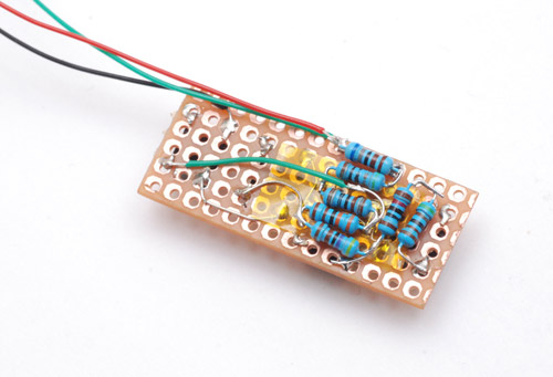
When I made my tic-tac-toe game I used a bunch of resistors and an analogue input to make the keypad use one pin. At the time I had virtually no concept of how electronics worked so I never worked out why it was so flaky. My solution was to add a calibration step which readjusted the values on each powerup. But now I know better. The resistors should go between power rails and act as a potential divider, then you always get a fixed voltage, or fraction of the reference voltage. Here's a nice site with an explanation - turns out this is a common technique.
I thought for a long time about how to mount the switches, but eventually caved and stuck them on some protoboard. The four on the left make a D-pad, and the rightmost button will be a freeze button to enter/exit time-setting mode.
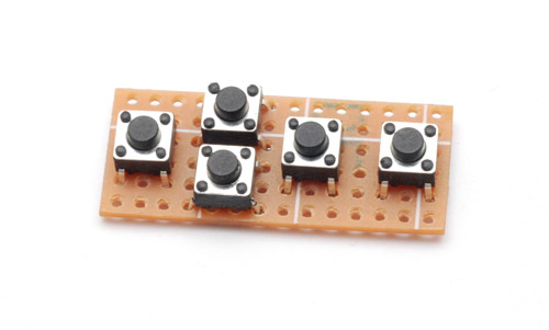
Didn't have quite the right resistors to hand so some bodging was needed. Kapton tape is always useful.
I pushed them all to the side like that to try and fit into the gap in the wiring where the controls are going to go. It sort-of worked.
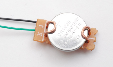
The CR2032 battery that came with the clock module was too large to be stickable to the back of the clock. I bought a CR1225 instead (if you weren't aware, the 'CR' is the chemistry and the numbers refer to diameter and thickness). I made a simple holder for it.
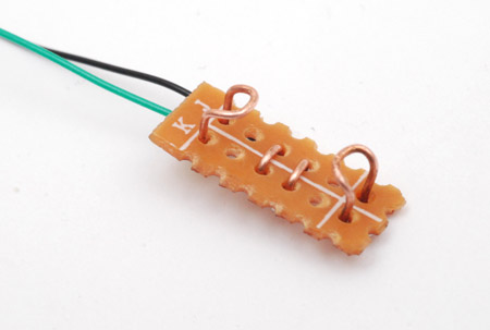
It works rather well.
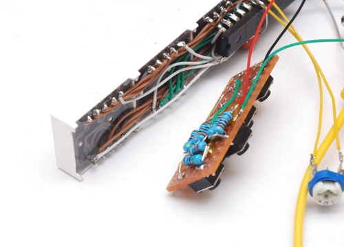
Now for the fiddly assembly. I stuck the crystal straight to the legs of the DS1302, which got the same treatment as the earlier chips. I made a half-hearted effort to keep the serial lines away from it in case it affects the timing. For the ATtiny85, I bent the legs outwards instead of snipping them, to allow me to fit a test clip over it and reprogram if the need ever arises. I suspect it will at some point.
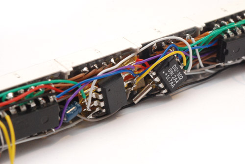
There's a reservoir cap showing, I also added 100nF filter caps to each MAX7219 chip which really improved their performance, actually. They were cutting out randomly when the brightness was at maximum, but fine when they were dim. The filtering means they work well at all levels. Annoyingly it does actually show filter caps for each chip when chaining them together in the datasheet.
Here are some wide images - click for full resolution.
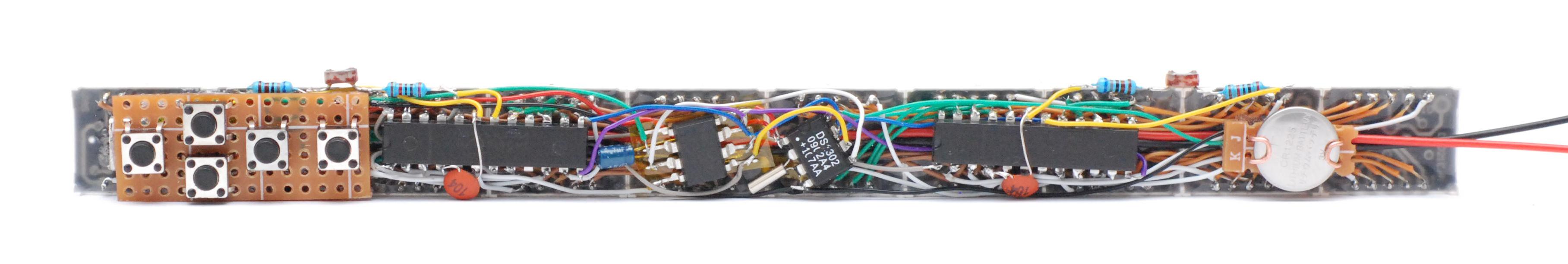
Pah. Printed circuit boards, who needs them? The buttons do stick out a fair bit, as does the battery, but on the whole it's a pretty compact creation. The time-setting routine is as follows: press the freeze button, and the clock stops with a digit flashing. Left/right changes which digit flashes, and up/down does increment/decrement. Unfreezing waits for the button release, so it's very easy to synchronize with an accurate time source. It doesn't (yet) prevent you from typing in nonsensical values, such as the 31st of Feb or 2600 hours. This would require bags more effort and the interface code is already longer than the rest of the code combined. Writing nonsensical numbers to the clock chip results in 'undefined behaviour'. We shall see how that goes.
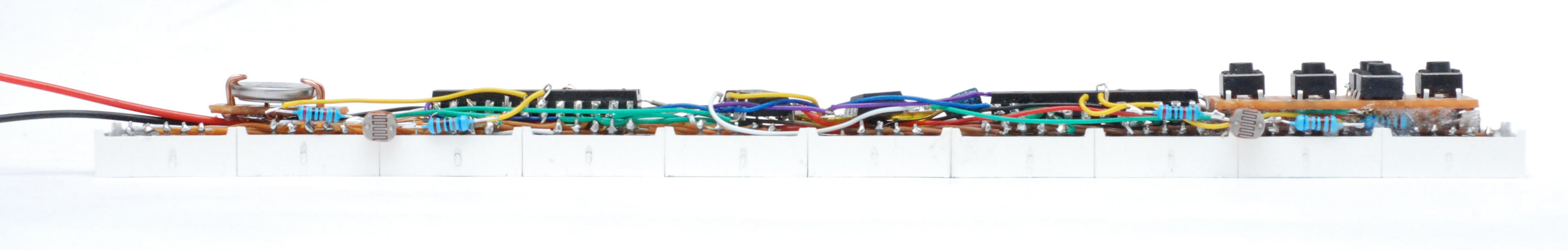
The last thing to do in terms of hardware is the brightness control. After some testing I was happy with placing an LDR in series with about 27KΩ (to limit the max brightness) straight into the MAX7219's Iset pin. I didn't bother with the current mirror, just used an LDR for each chip. It may have been tidier with a current mirror, since the LDR could have gone basically anywhere. I put them sticking up like that to try and ensure that equal light hits both.
I had in mind an additional brightness adjust using the keypad but I don't think it's neccessary. When it's bright, the whole clock consumes around 140mA. Waving your hand over it lowers that to 70mA, and the room lights off at night drops it to 8mA, which is perfect. It may be that this analogue solution would benefit from a correctional curve, since most of the sensitivity appears to function at the lowest light levels. I don't mean a digital correction, I mean placing a calculated amount of resistance in parallel with the LDR, the same way you can approximate a log pot from a linear. I suspect the current/brightness/human eye sensitivity relation to be nonlinear - more investigation needed.

Right. Well. That was fun. I'll consider doing the atomic clock in the future. The future... hmmm... time is ticking away. Quite visibly.