Fun with Photomultiplier Tubes
16 Jun 2016Photomultiplier tubes (PMTs) are the most sensitive light detectors you can get.
They are also just about the only vacuum tubes which are not obsolete.
One application for photomultiplier tubes is in conjunction with a scintillation crystal, which emits photons when hit by ionizing radiation, producing a very sensitive radiation detector. And one application of this, is a gamma camera.
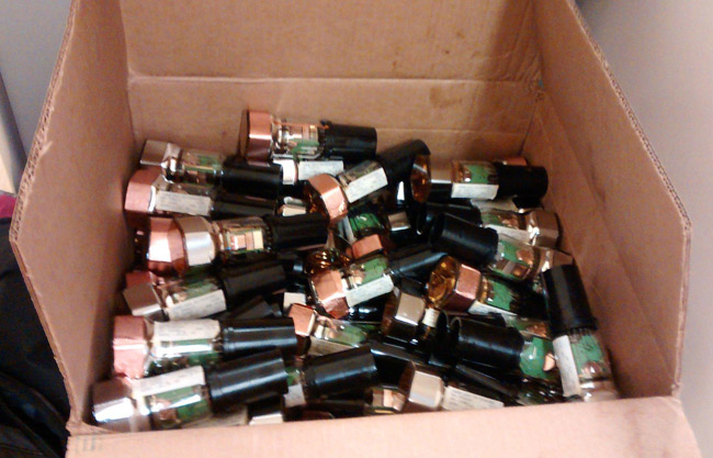
Gamma cameras take an image (usually of a patient pumped with radioactive material) by combining scintillation plates with arrays of hundreds of photomultiplier tubes. The important point is that, like all medical equipment, it needs upgrading, and if one knows the right people, one can get one's grubby hands into a box of over two hundred PMTs!
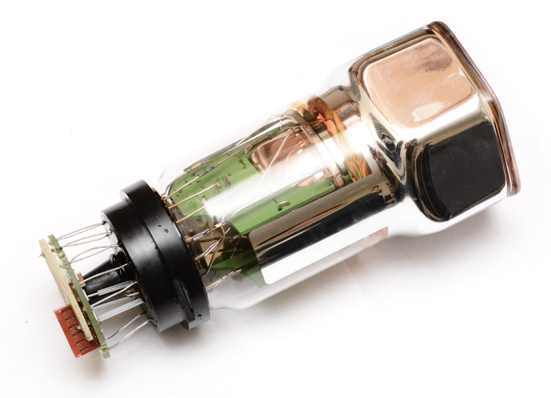
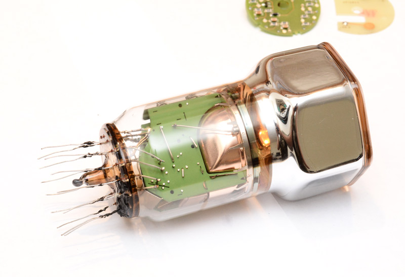
Here is an individual tube.
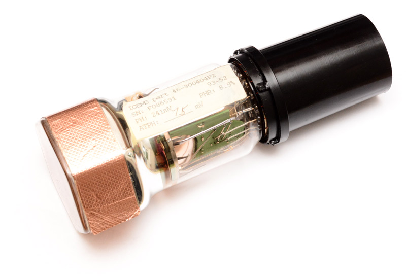
The label reads: IGEMS part 46-300404P2
The manufacturer is GE, and I gather these were made round about the year 2000, but there's almost no information available about this particular tube on the net. No datasheets, no pinout, nada.
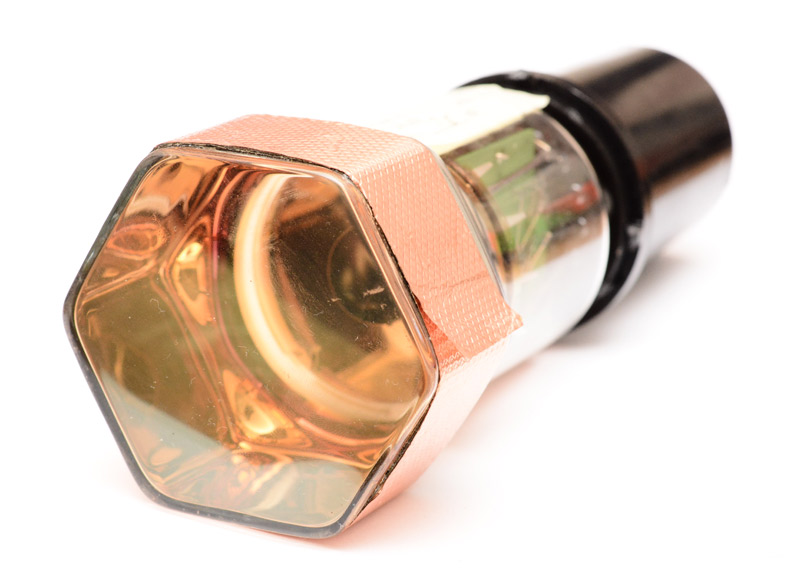
The front is 6cm across, the length is about 17.5cm.
Obligatory 'How PMTs Work' Section
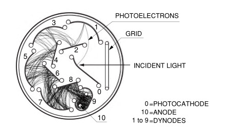
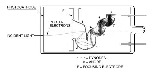
The textbook picture of a PMT involves a Cathode, Anode and lots of Dynodes in-between. It starts with the photoelectric effect, light causing an electron to jump out of a material, and then high voltages electrostatically accelerate the electrons into the dynodes, each time gaining energy and with each collision knocking free more electrons. The cascade ends with the anode collecting the charge and turning it into a signal.
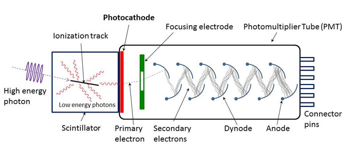
That's the theory anyway. In practice it's a little more convoluted - special photocathodes to maximize emission from certain wavelengths, and bizarre dynode geometry for the best balance between linearity, dark current, temperature stability and so on.
An excellent PDF file is available from Hamamatsu, a manufacturer of PMTs, here. It serves as both a manual and reference for actual designs of PMTs beyond the usual simplified diagrams.
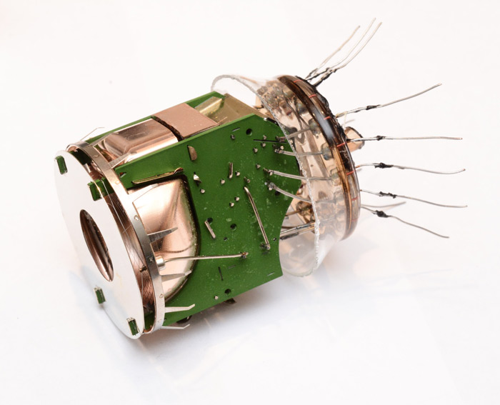
Teardown
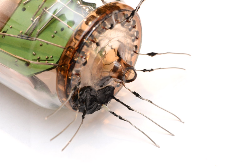
Since we have several tubes to spare, it is mandatory that we tear at least one of them to bits. To bits!First step is removing the plastic tube at the base. This comes off by breaking or levering back the tabs around the rim.
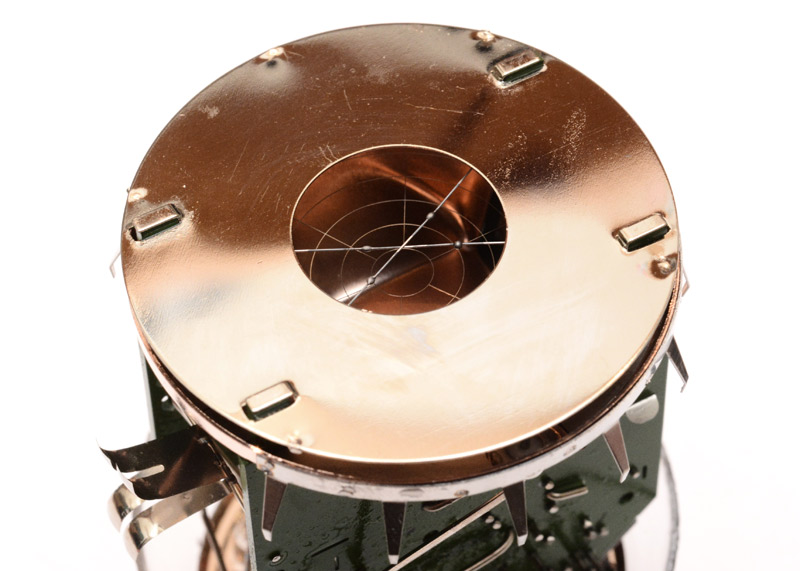
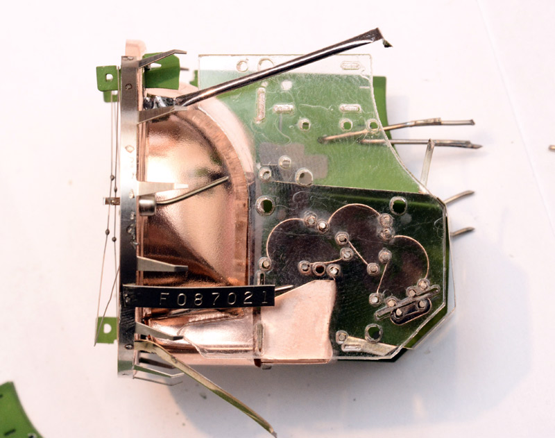
The label has been removed, underneath it is just an extension of the internal silvering. There are springy brushes in contact with it, this is actually the connection for the photocathode. So it seems it the entire silvered head and the glass front is all at the same potential.
There's a connector for a ribbon cable and also two gold test pads. Presumably the high voltage comes in on the test pads since the ribbon cable isn't rated for it.
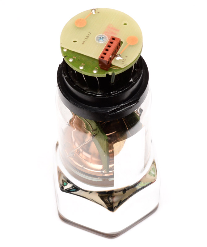
The test pad board was just soldered in place and a screw through the middle. The next board is more interesting but nothing more than jumpers on this side.
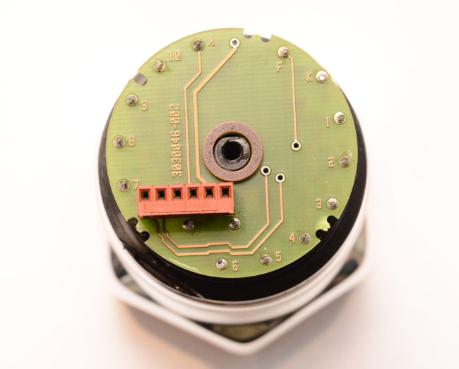
I snipped all the legs to remove it.
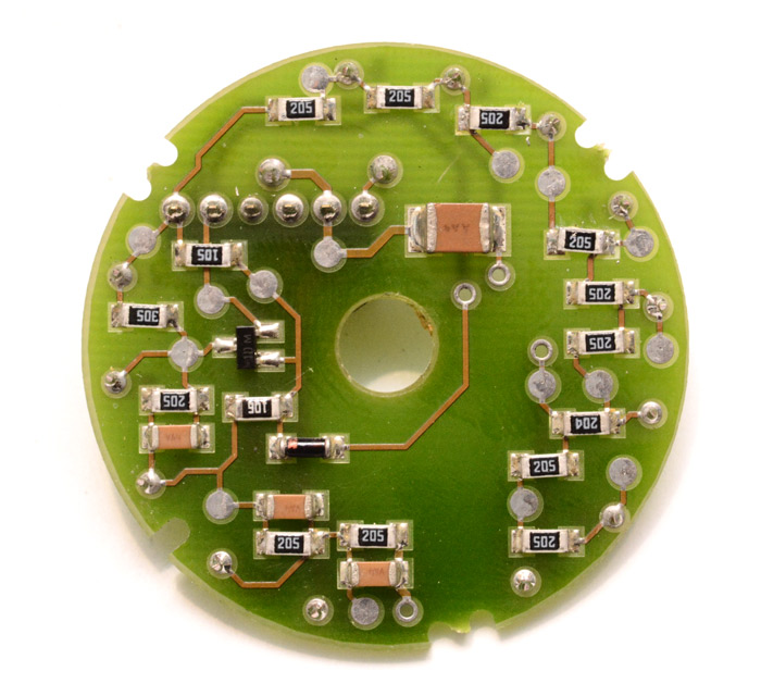
Obviously it's a little more than just a resistor network. We'll return to the circuit later.
The black rim was filled with some kind of silicone potting compound. To my surprise, it was possible to just lift this off, with all of the legs sliding through.
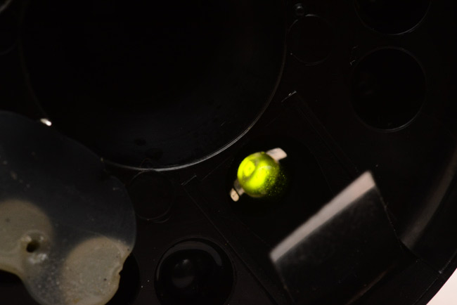
Something I almost missed, in the black base, there is an LED embedded. It was hiding under a silvery tab, I would guess some kind of aluminized plastic or mylar which cuts out 99.x% of the light.
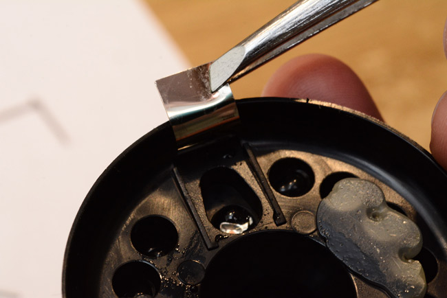
With the tab bent back and 3 volts pumped in, yep, that's an LED. Obviously it's for testing the thing is working correctly, but evidently PMTs are so sensitive that the full brightness of the LED would have no diagnostic value.
Back to the tube. Time to break the vacuum.
The base here, that's actually brown tinted glass. But the rest of the colour in the tube, the orange at the front, was a coating which disappeared within seconds of breaking the vacuum.
Totally transparent now. Looking at one of the intact tubes, you can see it was actually a coating, not some gas filling. Around the collar there's a stripe of it, although it's very difficult to capture on camera, you can just make it out here:
It's my understanding that the coating is the photocathode. According to Hamamatsu, the most typical photocathodes used in scintillation counting PMTs are Bialkalis, which are made of two types of alkali metals. Chapter 4 of their manual lists lots of photocathode materials and their properties.
Did the photocathode evaporate/sublimate? Or did it oxidize in contact with the air? I cannot say.
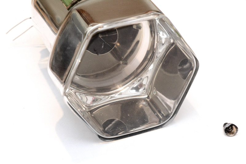
Next step of the teardown is to cut the glass. I used my normal glass-cutting technique, diamond grinding wheel under running water. Took about 30 seconds to go all the way around, then we can pull out the internals.
The reason for the running water is to both cool the cut and stop glass dust going everywhere. One slight disadvantage is that the insides had now been misted with water. Please forgive some of the following pictures if they appear to be a little moist.
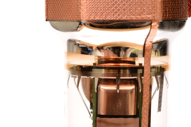
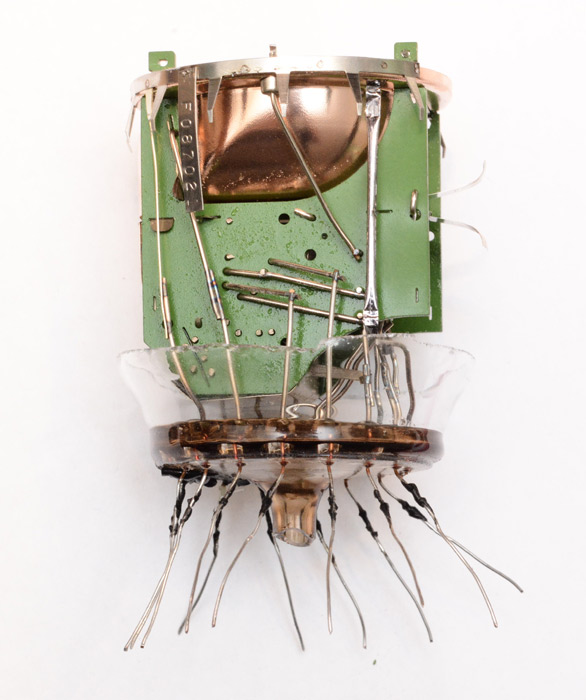
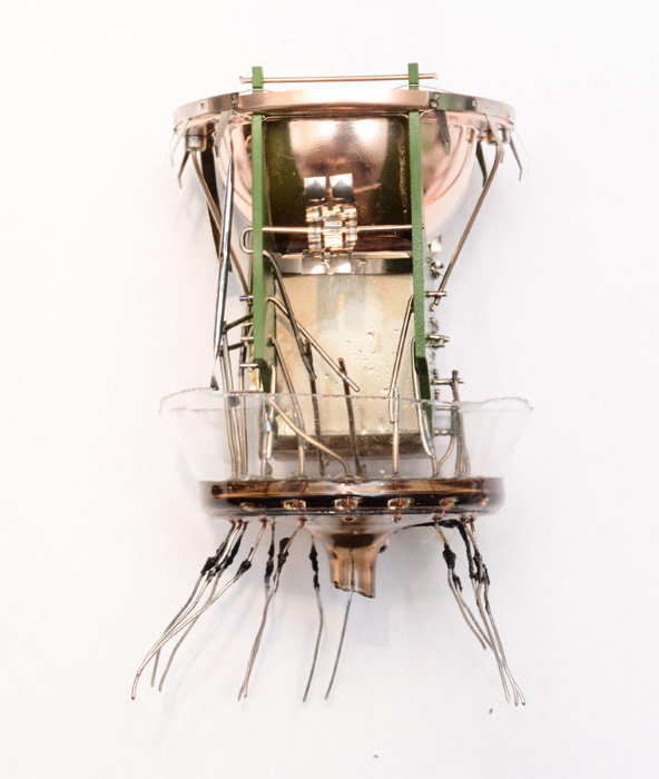
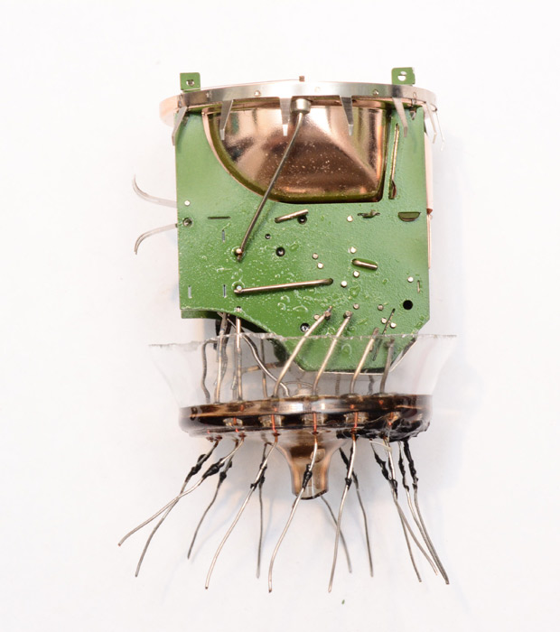
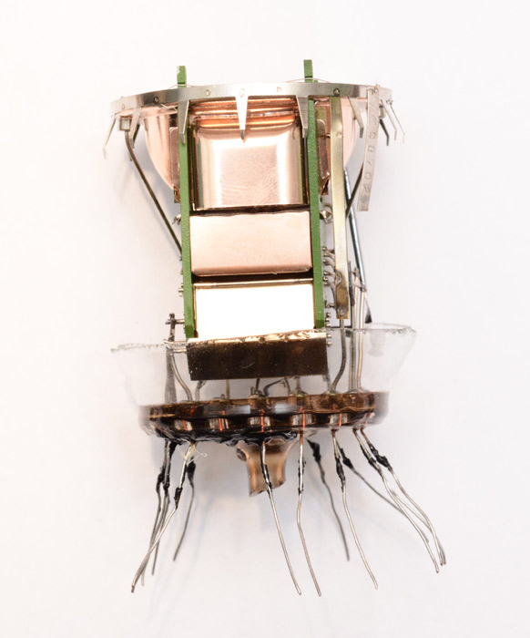
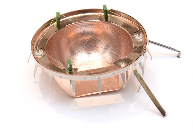
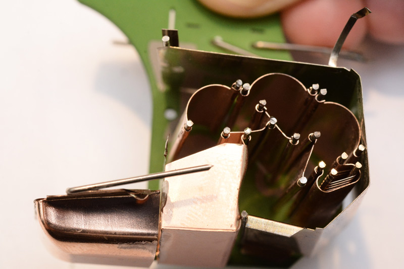
Here's the main unit.
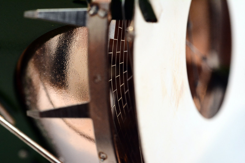
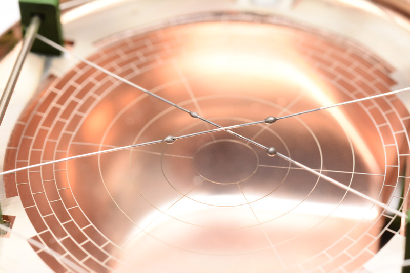
The front part I am going to call the focusing plate, and looking through it you can see the spider's web of electrodes inside.
Peeking around the side you can get a glimpse of how the web gets denser towards the edges.
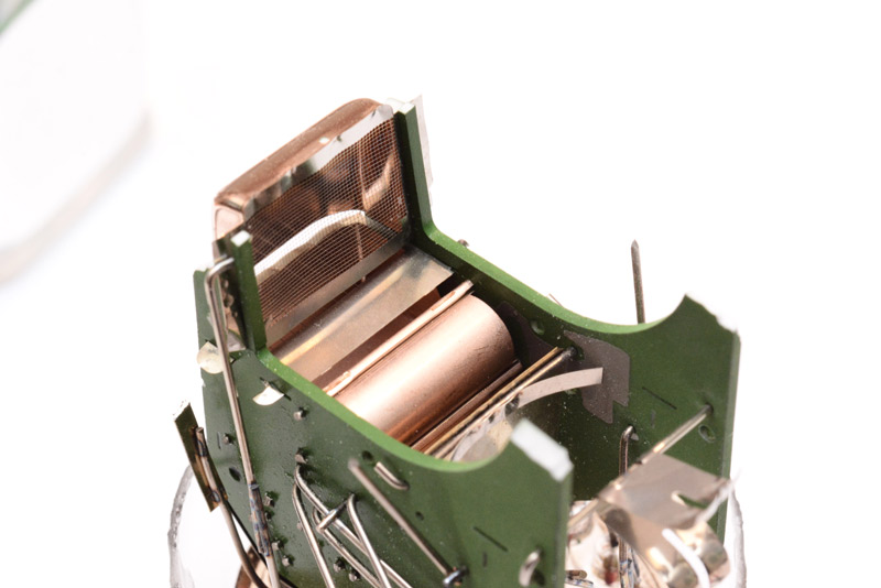
Time to remove the focusing plate, which was intricately spot-welded to bars going through the green support boards.
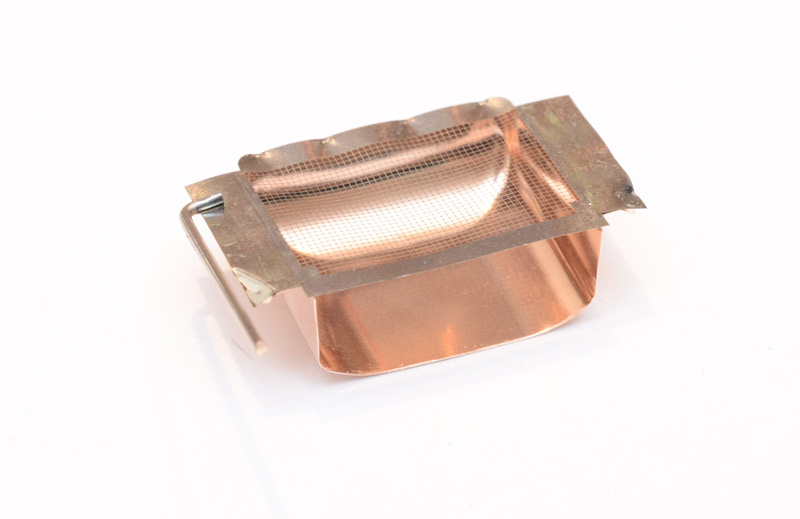
Inside we can see that the mesh over the second dynode is even finer.
I don't know what the chemical on the wires is. Maybe I will research this later.
Before going any further, I thought I'd take a few profile shots.
Incidentally, all of the joints are spot welded, not soldered. Possibly to avoid tin whiskers? Or maybe just for durability.
In the picture above, the connection on the left, I think I severed it when I was cutting through the glass. It's some kind of foil rolled into a tube, why, is another question I cannot answer. One end is connected to the first dynode, the other seems to go nowhere.
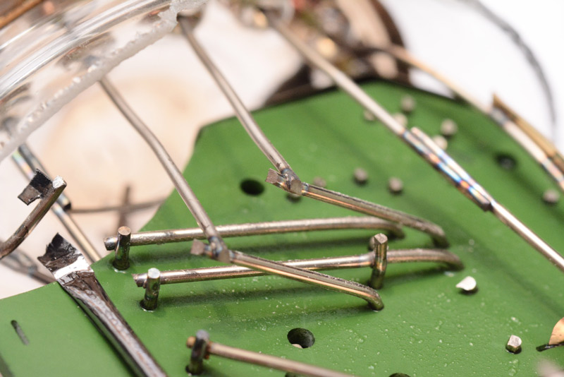
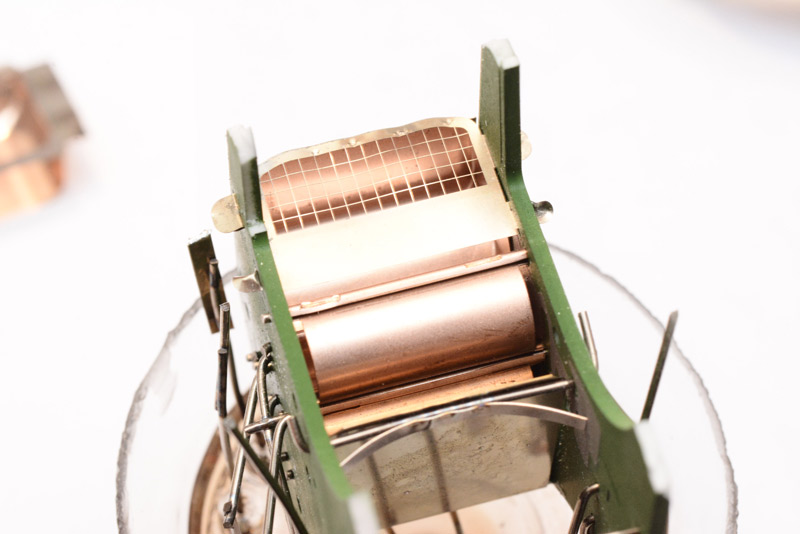
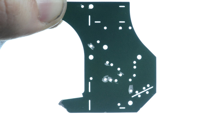
To remove the focussing elements and the first dynode, I decided to cut the green support boards. These turned out to be made of some kind of ceramic, not FR4 or fibreglass like I had thought. It's brittle, white on the inside and has a musical ting when you hit it.
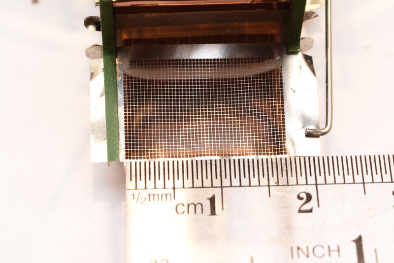
For a sense of the scale of the mesh on the second dynode:
The first dynode and its focusing wires, in isolation. Unfortunately as I cut the green board, one of the supports shattered, but you can still see the main structure. There are insulating rings around the posts the wires connect to, so it's obviously at a different voltage.
Then the second dynode.
I gather the dynodes are Beryllium Copper, and may even have (or had) a coating of some kind to maximize electron emission.
The mesh over the third dynode is much more coarse.
Time to start cutting all those wires and remove the lump of glass at the bottom.
The task now is to pull one of the green sides away to get a look at the internal structure. Unfortunately, once I'd trimmed the wires enough to do that, it all fell to pieces.
In the shot below, I have tried to balance all of them in their correct places, but they tend to flop around. This is with the second and third dynodes in place. You can see that the final part, the anode, is like a wire ladder.
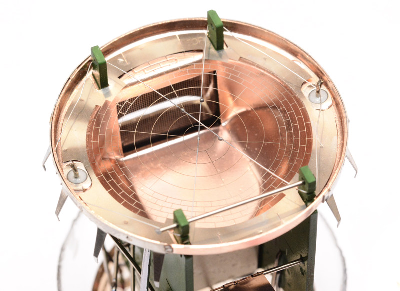
I was thinking, hmm, wouldn't it be good if these could be held in place by the support board, but we could still see them? Then we'd get to see how they're normally held, like. What we need is a transparent support board. If only that were possible...
I held up the part to be silhouetted against the sky as you can see. Then photoshop > levels > drag the black point all the way to the right, then image > mode > bitmap. Calipers on the original to set the scaling right, then import into moshidraw and getOutline. Acrylic in the laser cutter and in a matter of seconds we have a transparent replacement of it. Awesome eh?
Ta-da!
Annoyingly there are some fingerprints on the inside surface that I can't get rid of, but it was so fiddly get all of the wires into the right holes that I don't want to pull it apart again. Also, don't forget there's a possibility that dynodes 4 through 7 are in the wrong places, since they fell out during the initial teardown. I'm reasonably confident that's the correct assembly though.
That about concludes the teardown, now let's see if we can make sense of the circuit and get one of these things working.
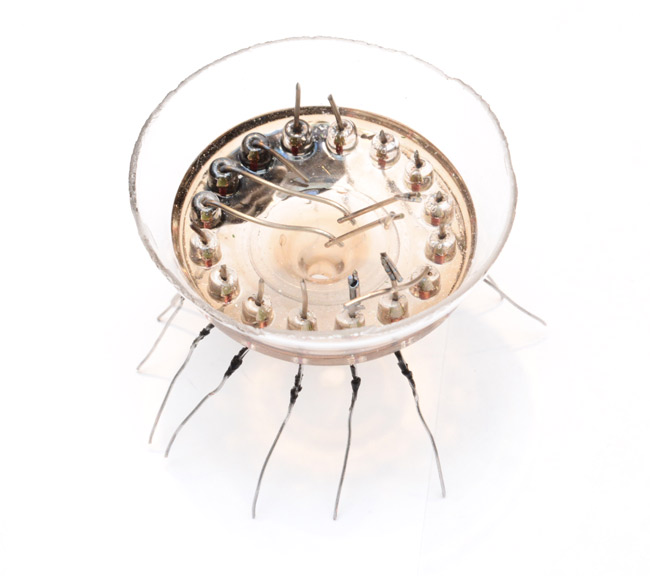
The Circuit
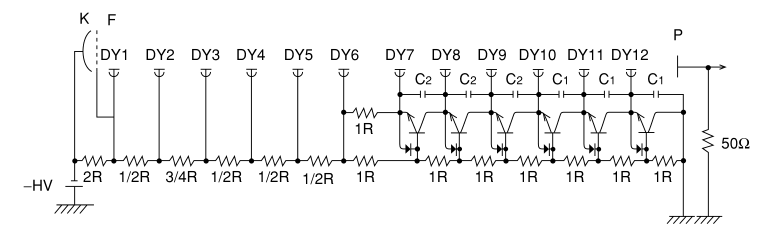
To use it we need to know what voltages to stick where, and since there seemed to be no info available, the only thing to do is to trace out the circuit.Interestingly this tube seems to be a hybrid design. The geometry isn't listed in the Hamamatsu booklet, but has similarities to two (or even three) of their diagrams. From the book, here's the Circular-cage Type:
Which looks pretty similar, but the front of ours looks more like the Box-and-grid Type:
There is also a Mesh Type, and there are certainly lots of meshes. See section 4.2.1 of the Hamamatsu PMT handbook. Similarly the circuit does not correspond to any one diagram. The standard layout is just a string of resistors to divide the voltage evenly, but in order to keep the idle current sensible (remember that you're applying hundreds of volts) these resistors need to be very high-valued. If there's light enough to cause a substantial amount of charge to bounce around the dynodes, the voltage of the last few dynodes can 'bend' with the light levels. Sticking capacitors across the last few resistors is the standard remedy for this, but according to the book there are several other techniques as well.
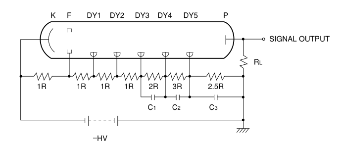
Here's another look at our circuit:
Just in case the reader is not familiar:
- Black rectangles with white numbers are resistors. The numbers are similar to the colour codes, in that the last digit is the exponent, so 205 is 20 x 105 = 2,000,000 = 2 megaohms.
- Orangey-pink rectangles are ceramic capacitors, they don't have values printed on them.
- Shiny black with orange stripe is a type of diode, at a glance there's no way of telling what it is, at this point I would guess a zener.
- The three legged part could be a transistor, or a diode, or anything else that fits in that package.
The markings on the three legged part are difficult to determine, it looks like it says "1D M", but the D is severed and it could be a 1 followed by a backwards C. But the space/slightly different font size implies that M is a date code, and if the part number is 1D it would make this a BC846 – NPN transistor. (Surface mount transistors have a ridiculous and extremely dense marking scheme which you just have to look up.)
Since there's just the one transistor, my first assumption was that it behaved as a buffer on the anode output. This is quite common, and the Hamamatsu book has a lot about buffers and preamplifiers, section 5.3.
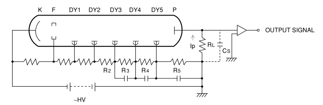
RL is the load resistor, used for turning the charge collected into a predictable voltage. There are many more diagrams of the different amplifier configurations. 'S a very good PDF.
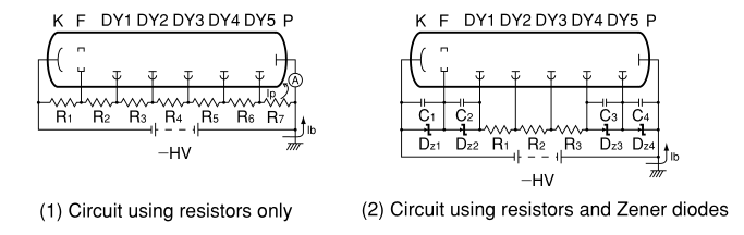
There's only one diode, too. Zener diodes are used for predictable voltages, in fact they are basically the simplest voltage regulator. Sticking them across every dynode is sometimes done.
Could it be a zener on only the last stage? Hmm. The only way to find out is to trace out the circuit. So I did.
The other side of the circuit is just jumps, so I drew them on here. D1, D2, D3, D4 are the first four dynodes, labels Dn were not actually traced out, but it's pretty obvious which dynodes they go to. The row of pins is the header connector.
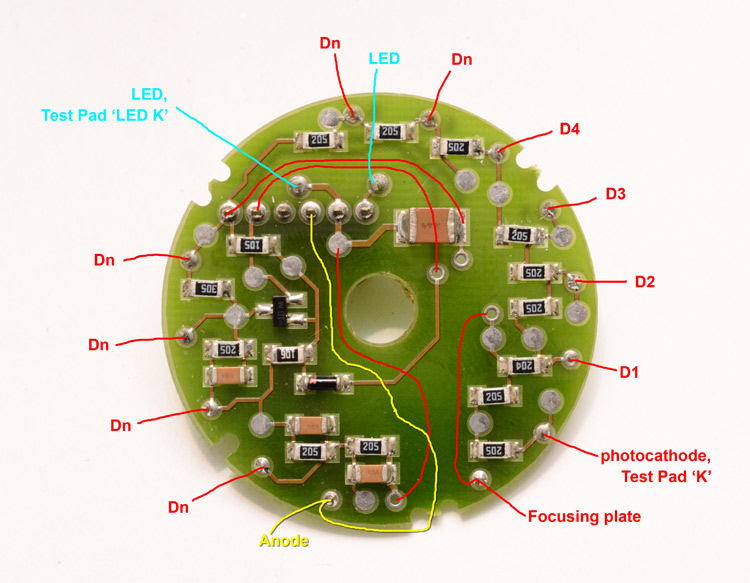
The obvious thing that strikes me is that the anode is completely unconnected to anything else, which actually is all we needed to know. This doesn't tell us whether the PMT is grounded-anode or grounded-cathode, but since the LED and the header connector are at the same potential as the last dynode I think we can assume it's grounded-anode. So the test pads are Ground and Negative-high-voltage, the anode connection is the signal out – we probably could have guessed that without tracing it out. But now we know the pinout.
The other thing is to actually understand the circuit, although I'm sure it will just work, I finally spotted this diagram of voltage regulation, using transistors and diodes:
From Section 5.1.7, and it actually mentions scintillation counting as the application. The "use of transistors in place of the voltage-divider resistors at the later stages can improve the output linearity degradation resulting from the divider current limitation."
Well there you go. So it seems we have just one node regulated like that, capacitors on the last three and resistors for the rest. Let's fire it up.
Power supply
In order to shout "it's ALIVE!" we need to pump it with high voltage. Obviously.
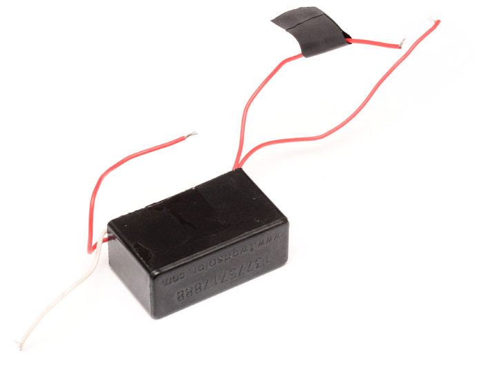
It also needs to be a very clean power supply because of the sensitivity of the device. I immediately knew what to choose:
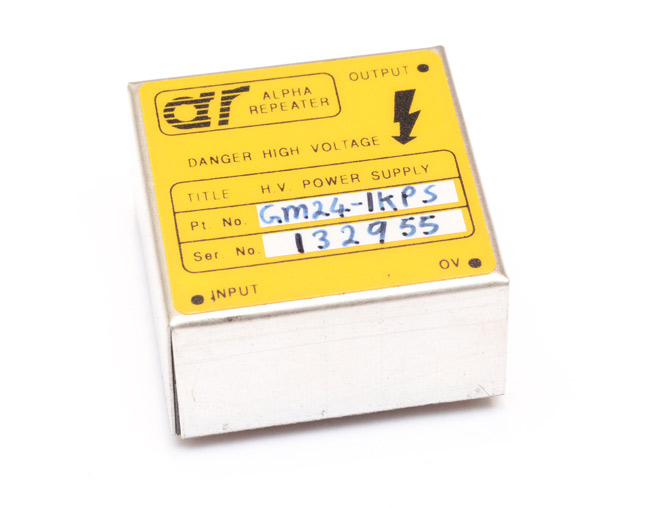
This little wonder is a step-up module (a boost converter) which takes a few volts of DC in and spits a few hundreds volts of DC out. I grabbed it at first since it came from a DAP meter (Dose-area-product meter, essentially a glorified geiger counter) which also needed to measure very small signals with a huge DC bias.
Like most of these high-voltage modules, it's entirely potted so as to keep an air of mystery about it.
In order to get a negative high voltage, well, the simplest thing you can do is power the module from batteries and connect the HV output to ground, and use the 0V terminal as the HV supply.
I wasn't entirely sure what the in and out voltages should be since it wasn't marked, but vaguely recall the device I pulled it out of fed it 15V, so starting small, I gradually raised the input up to that. The output followed but saturated somewhere around 300V. In retrospect, now I'm writing this, I think I may have just been drawing too much current from it because of the way I measured the voltage.
I'm uncomfortable sticking a good chunk of a kilovolt into my multimeter so I set up a potential divider to measure a known fraction. The resistors I have are probably only linear up to about 100ish volts, so I stuck ten of them in a line and just measured the voltage on the last, multiply by ten to get the full voltage. Without really thinking I'd used resistors of a few kilo-ohms, which actually means there were tens of milliamps flowing at hundreds of volts, which is multiple watts, far more than this little unit was made to cope with.
Anyway, I did test one of the tubes out at 300V and found it definitely responded to light, the first thing I noticed was the flicker of my laptop screen, and changing its brightness noticeably changed the duty cycle of the waveform. Excellent! But we needed higher voltages really.
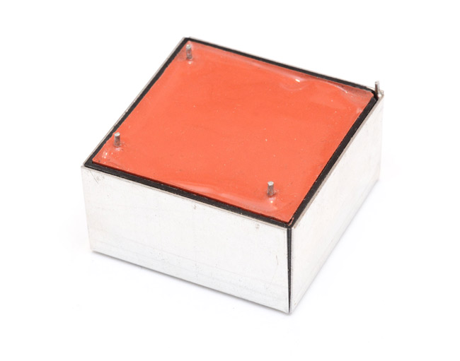
I rummaged through my drawer and found this, which had even fewer useful markings (none), but I seemed to recall being a 3V to 700V unit. As it turns out, I was wrong, and it's a 3V to 7000V unit.
Its actual intended use is for electric ignition type scenarios. The way these work is totally unregulated, the voltage just continuously rises until it either breaks down the air in a glorious spark, or breaks itself. The speed of the arcing is based on the distance it has to arc, varying from a few sparks a second to a continuous buzz at about 1mm apart.
(I have another module which claims to go up to 400kV, which cannot be true, since a good rule of thumb is 100kV per inch of arc. The arcs were nowhere near four inches long, more like half an inch.)
While I still had 700V in my head, I managed to destroy a multimeter in the process of working out the polarity of the output wires. With no load (or 10MΩ, or whatever the voltmeter's impedance is) it just built up voltage until it arced internally. D'oh. The correct procedure is to put a load resistor across it. Like I mentioned above, to have high-voltage resistances, just string a bunch of them together in series.
Since the frequency increases as the load resistance decreases, and the voltage decreases with it, using the correct amount of resistance I was able to get 600V continuous out of the unit, with a ~1kHz ripple. One benefit of this module is that it's isolated, that means we can generate a negative high voltage while powering it from a grounded bench supply. The only disadvantage is that if we accidentally knock one of the leads from the breadboard, the voltage will shoot up until it arcs. Or electrocutes you. Or blows up.
The Multiplying of the Photons
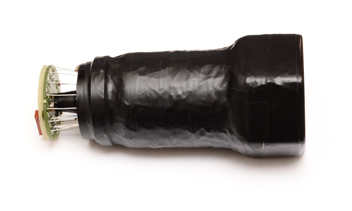
I wasn't sure whether to make a video of this, or take pictures, or what. The problem is it's so bloody sensitive that it needs to be in complete darkness to work, which doesn't make for particularly interesting footage. But here's the set-up. First, to block all other light, I wrapped it in a few layers of aluminium foil, which is a very good and cheap light-blocker.
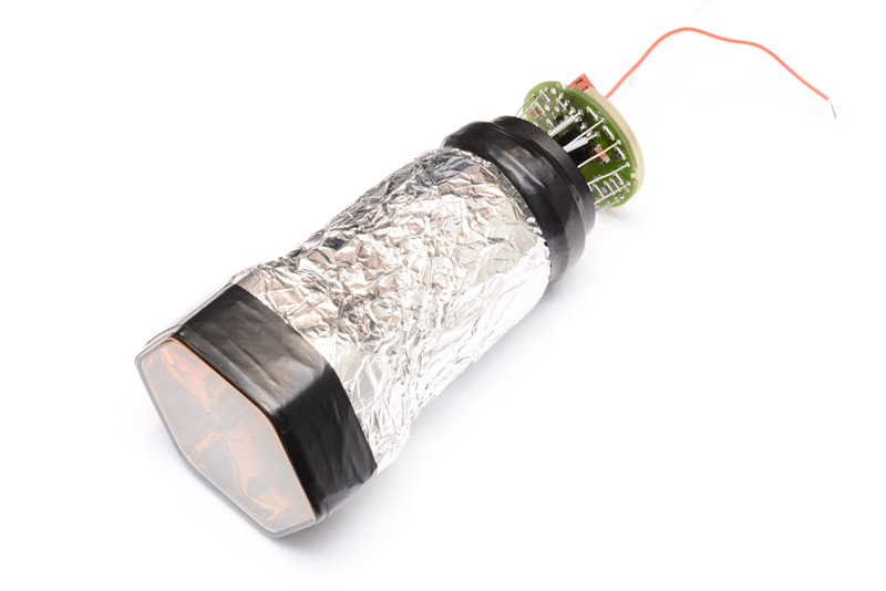
Then I wrapped all of that in black tape, since the foil was now at the photocathode potential, which would have made touching it an unpleasant experience.
To listen to the anode, one lovely diagram in the Hamamatsu book showed this:
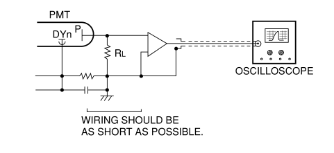
Cute. I didn't bother with anything like that. Straight into the oscilloscope and let the input impedance be the load resistance.
Boy is it sensitive, and I had to unplug the power supply for my laptop which was throwing off too much EM noise. The ripple of the 600V power supply was an issue, and the first thing I did was just smooth the anode output with a 100nF capacitor to ground, which combined with the 1MΩ input of the scope gave a lowpass of about 1.5Hz, or if you use the 10x impedance then 0.15Hz. Enough to cut all the noise out but also smooths most of the pulses away. Also since this is not AC-coupled, i.e. capable of DC measurements, the capacitance behaved more like an integrator than smoothing.
Better to remove the noise at the source, but the highest-rated capacitors I had were only 160V. I eventually found five high-voltage capacitors of the same value (1μF) and strung them together in series, which gives a 200nF, 800V capacitor. (If they were all different values, we would not be sure of the voltage being divided equally between them.) This actually worked really well and the ripple dropped to an acceptable level.
The picture below is pretty busy. But the breadboard has five resistors as the load and sensing (the oscilloscope probe is connected to the first, to keep an eye on the total voltage) and then the five capacitors, which are only connected across the output of the high voltage module, their legs are in alternating rows of the breadboard to the resistors.
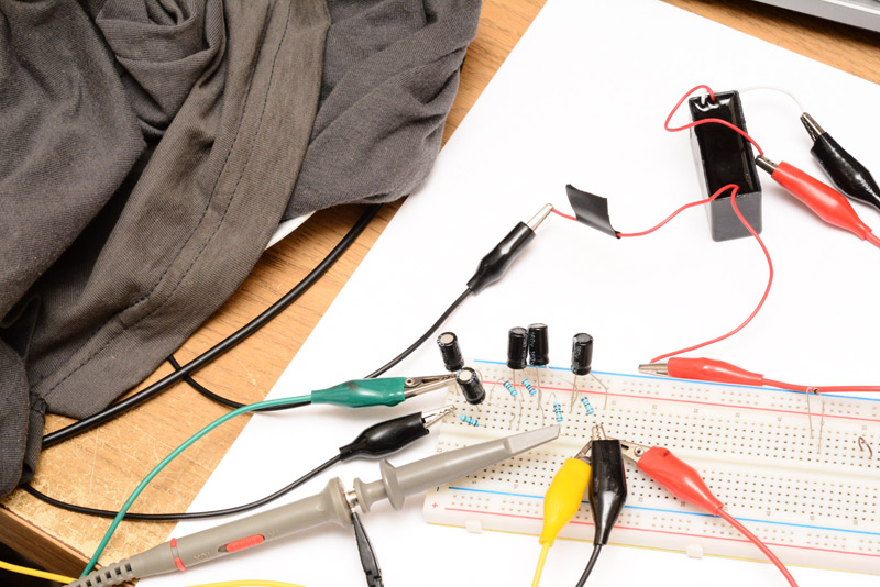
The pile of rags on the left is what I'm using to keep light out of the PMT, which is facing directly down, flat against the desk.
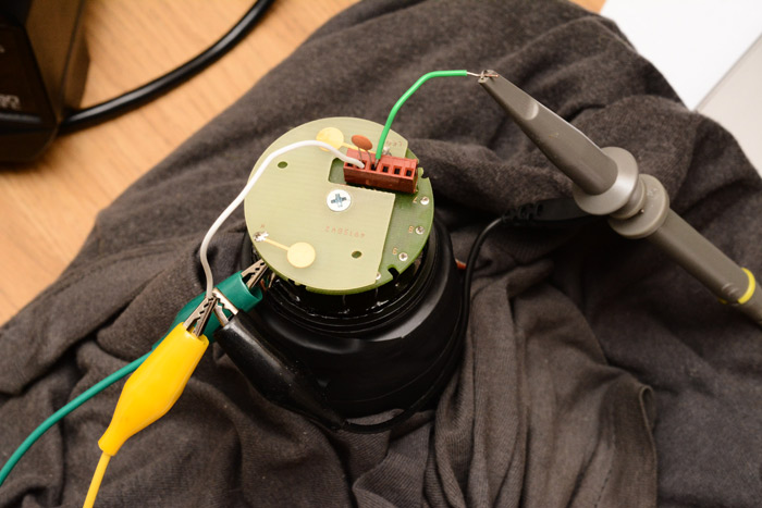
High voltage, ground, and the anode to the scope. 100nF from anode to ground still (as I lowered the light levels, and turned the scope amplification up, the ripple getting through became significant again). Eventually I had enough black cloth on it that shining a torch at the mound made no effect on the output.
Hooray! And after all that, I didn't really have anything of amazingly low light to look at. But one thing I had wanted to confirm was the triboluminescence effect. When you rub crystalline substances together, they emit a teeny-weeny amount of light.
I put a small spoon of sugar on a plate, then laid the PMT on top, and built up my rag cloth covering over it until I was satisfied there was no light. The dark current was producing about 4mV.
Then, lightly touching the back of the tube so that the sugar crystals were rubbed together, whoosh! multiple pulses, between 5 and 50mV in height. Triboluminescence confirmed.
I connected the output to my speakers and turned up the gain, and then you can actually hear the pulses. To be honest as I agitated the sugar it just sounded as if I had a microphone in contact with it.
What else to look at? I'll have to think about it, since I spent so long looking at and playing with this tube and yet have nothing really to do with it. I need to try and get hold of a scintillator.
In the mean time, what should we do with the rest of the tubes?
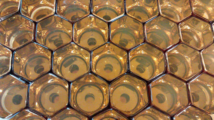
Since they tesselate, the current plan is to turn them into an incredibly tasteless coffee table.