
Phase-locked Inverter
12 Jun 2019Progress: Complete
Intro
I was contacted by someone who was trying to build a Groundhog Day Alarm Clock. This, being a prop from the film, is a 1970s Panasonic flip-clock that only ever plays Sonny and Cher's "I got you babe" when the alarm goes off. They had followed a tutorial on how to build this, using an Adafruit Audio FX sound board, so there isn't much to say about that.

However, the eBay flip-clock they had started with was a US model, designed to run on 115V 60Hz. A simple UK-to-US power adapter, like the one being used to run this clock so far, is just a transformer. So it takes the UK 240V 50Hz, and outputs 115V 50Hz. Since the clock has a synchronous motor and uses the powerline frequency to tick at the correct speed, the result is that the clock runs about 16% slow, which is completely unacceptable.
There are a lot of different ways to solve this problem:
- Find a commercially made 50Hz to 60Hz adapter, if it exists. I can't imagine we're the first people to run into this problem. But, a quick search didn't turn up anything usable and at a usable price.
- Adapt a 60Hz inverter from something else. If we got hold of an Uninterruptible Power Supply (UPS) intended for the US market, we could take out the 60Hz inverter and run it from rectified UK mains. This wouldn't be very accurate for time-keeping, since it would just be based on the inverter's clock source which is unlikely to be good at all, but it would be a lot better than 16% slow. Another annoyance is that this would be a big high-power inverter, whereas the clock only needs a few watts. It would be nice to have a solution that could fit inside its case.
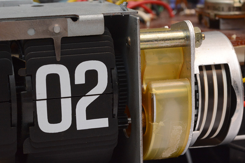
- Alter the mechanism to work on 50Hz. There are multiple approaches to doing this. The speed that the synchronous motor spins at is based on the frequency and the number of poles. It is not possible to rewire the motor to have a different number of poles, but maybe we could buy one. Another option would be to take a look at that gearbox on the output shaft, and see if we could find a different set of gears for it that would work. This would probably be quite a difficult thing to do. The motor's rotor has a spiral pattern on it, which is visible through a small window on the front, and gives a visual indication that the clock is ticking beyond the once-per-minute display updates. It would be nice not to ruin that.
- Replace all or part of the clock mechanism. If we could find another (possibly broken) Panasonic clock intended for the European market we could salvage its motor, its gear train or even its entire split-flap mechanism. I didn't have much hope for this though, because there are a lot of different flip-clocks with slightly different designs that probably aren't compatible, and if there were an easily available donor clock that ran on 50Hz then the project probably would have started with that to begin with.
- Go all-in and build our own 50Hz to 60Hz inverter from scratch.
The reader should not be too surprised to learn that I went with the last option.
Reverse Engineering
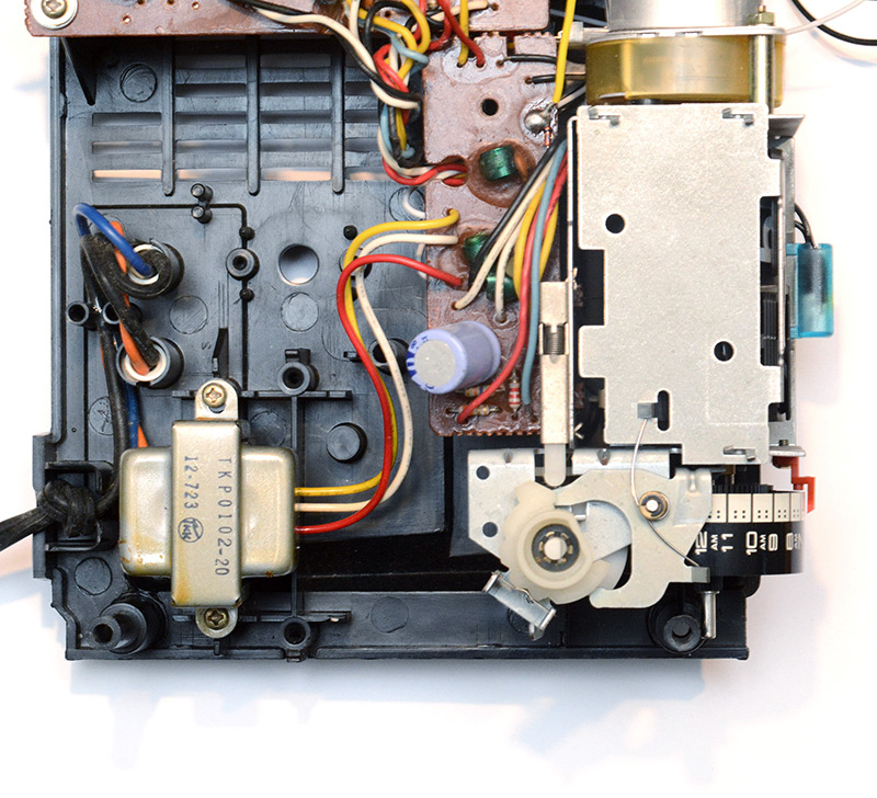
We'd already done a bit of poking around inside the clock. Most annoyingly, the sticker on the side of the motor was missing. This would normally tell us the details of what we need to drive it with.
The mains power comes in to a small transformer which has three output wires. The middle wire is a centre tap. The transformer is isolating so it's safe to poke around while it's switched on, and I measured the outputs to be 24VAC, or 12VAC between one end and the centre tap. Without looking too closely at the board, it's quite common to label the centre tap as "ground" and use the two phases to produce a dual polarity supply, e.g. +15V and -15V.
I did the measurement on the oscilloscope and it's important to remember that 12VAC refers to the root-mean-square (RMS) voltage. The peak-to-peak voltage is much more. Assuming a perfectly sinusoidal input, the peak-to-peak output is the RMS voltage multiplied by 2√2, so 12VAC is about 34V between peaks, and 24VAC is about 68V peak-to-peak. It was these voltages I measured on the scope, and then I worked backwards to get the transformer output.
The transformer feeds into a small board that has nothing but a few filters, made from capacitors and little coils of wire (inductors, or chokes). This is just to remove noise from the power coming in. From there the clock motor is driven directly from one phase and the centre tap. So, it's 12VAC we need to give it.
I did some searching and found someone else's repair video for a very similar clock, and their model still has the sticker on the motor. It was difficult to get a clear screenshot of this, here's the best I could manage:
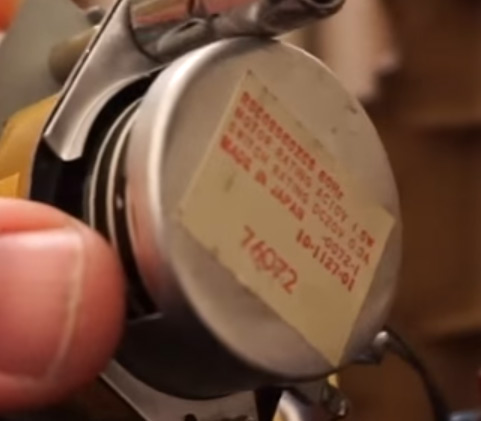
[unintelligible part number] 60Hz
MOTOR RATING AC10V 1.5W
SWITCH RATING DC20V 0.5A
MADE IN JAPAN
[more part numbers]
This is all we need to know, but I did investigate other parts of the clock. The radio is fully functional, with the dial directly turning a variable capacitor. The alarm has a snooze function. The electronics are quite old, no integrated circuits. In addition to the radio, there is a chirping siren alarm mode, which gets faster in a weird analog way. The modes are selected by an electromechanical switch that forms an integral part of the flip-clock alarm mechanism.
Right, let's get hacking.
Inverter plan
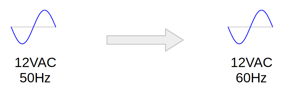
We want to take a 50Hz 12VAC input and have a 60Hz 12VAC output.
Actually it's a little more complicated than that. Rather than just a 60Hz output, we want the output frequency to track the input accurately. The mains frequency is carefully controlled so that clocks stay on time, but throughout a day it drifts up and down a bit. The question of cheating, by sticking a quartz crystal on our inverter and using that for timekeeping, has been noted, and duly dismissed. The right way to do it is to make the inverter output track the input frequency drift.
If you are not familiar with it, there are many pages online explaining the details of how the utility frequency is controlled. The idea is that while it deviates slightly from the nominal frequency, the long term average is much more stable than what you would get with a crystal oscillator.
Critically, what we care about is the phase error. Even if the frequency averages exactly 50Hz, the total number of cycles can be different to a static 50Hz waveform for the same period, and so the clocks would still drift. There is a very good page about monitoring the phase error on the European power grid by Pieter-Tjerk de Boer here.
So, our waveform output needs to track both the frequency of the input waveform, and its phase.
We are essentially building a phase-locked-loop (PLL), and our circuit needs to both rectify and measure the input signal. From there we synthesize a new waveform and send it to the output driver.
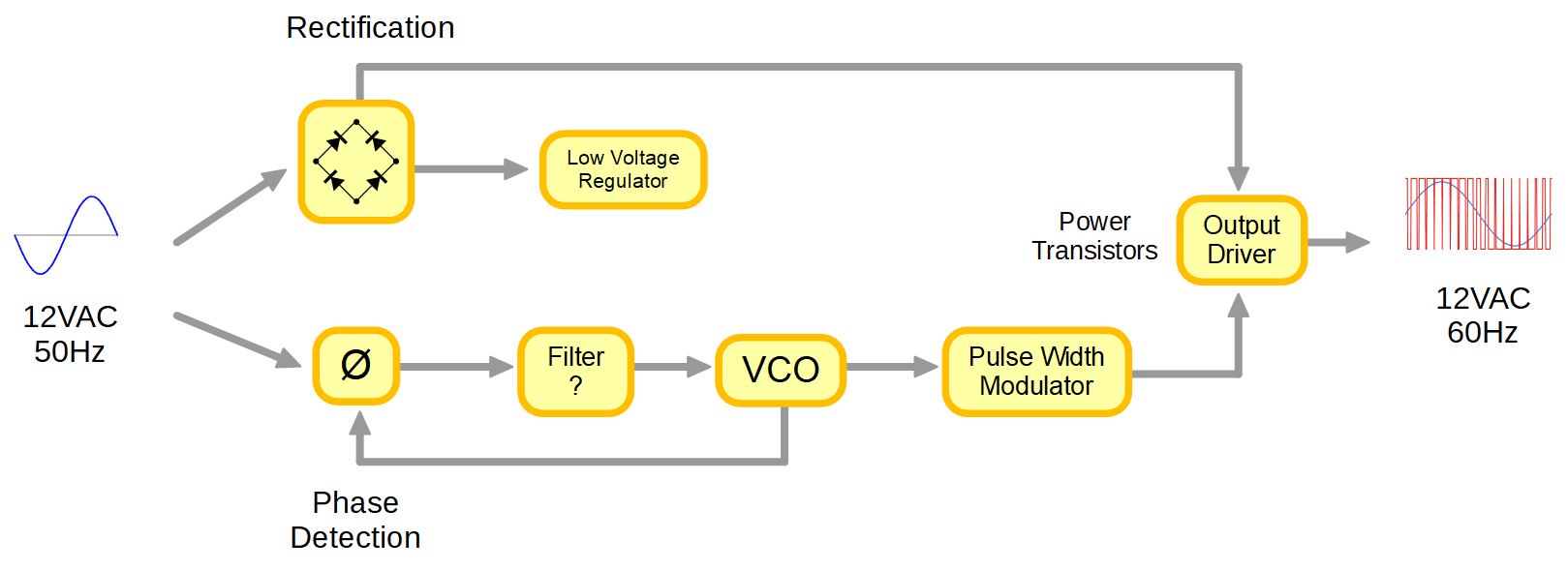
It would be possible to do this all using discrete components, but since we are living in the 21st century we'll be doing all the gubbins in the middle with a microcontroller.
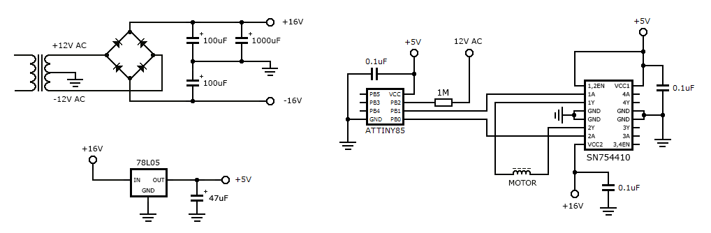
Rectification is done using a diode bridge, which is pretty standard stuff but the way that we wire it up will depend on how we want to do the output driver. The output driver will also be a bridge circuit, which adds a pleasing symmetry to the design.
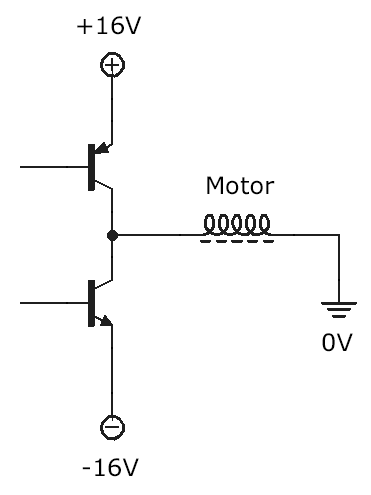
Since we have a centre tap, which the motor is already connected to, the conceptually simplest design is to construct a half-bridge driver circuit. We rectify the full swing of the output giving us a +/-16V supply. The half-bridge is constructed from just two transistors, one sources current from the positive supply, the other sinks current into the negative supply.
A problem is that our synthesized waveform will be at a much lower voltage, so we also need to add level-shifting transistors. Something like this could work:
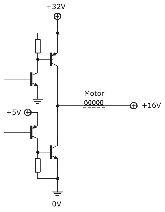
Now a further problem appears. The schematic above will work fine if the low voltage is referenced against the negative rail – for instance, we just stick a 5V regulator between the power rails and consider the negative rail to be ground. It's all isolated anyway, so the concept of ground is relative. But if we do that, it introduces problems for the phase-detection part. That bit will be considerably easier if the circuitry is ground referenced on the centre tap, which allows us to count the zero crossings.
Rather than mucking about with more discrete transistors it's simpler to grab an existing motor-driver IC which does the level shifting for us (along with having built-in protection diodes). I have a bunch of SN754410NE chips in a drawer which are described as "quad half-bridge drivers". These only do the type of level shifting I'm describing above, and if our driver chip's ground pin was connected to the negative rail then a ground-referenced microcontroller would not be able to talk to it. However, we don't need to worry about this, since if we have multiple half-bridges on the chip, we may as well ignore the split power supply and drive the motor in the conventional H-bridge way.
Two half bridges make an H-bridge, so now instead of alternately connecting one terminal of the motor between rails, we ignore the negative rail and alternately connect both terminals between the positive rail and ground.
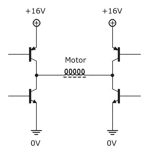
(Level shifting not shown, for clarity.)
This gets us the same result but in a way that we can control, and keeping the phase detection around the zero crossing makes the next bit much easier.
Clamping Diodes, Phase Detection and the Loop
For protection against electrostatic discharge, all microcontrollers these days have clamping diodes on their pins, which let voltages beyond the range of the power rails escape.
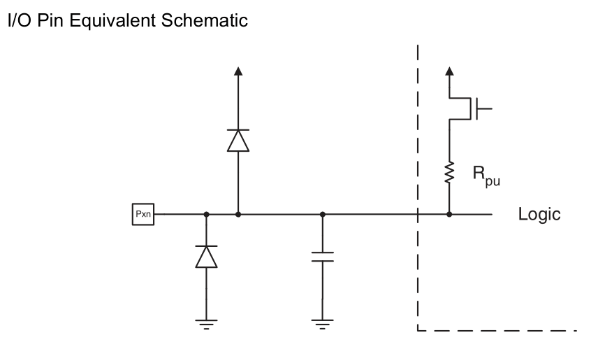
The presence of these diodes allows for all kinds of interesting hacks, and sometimes confusion if you don't know they're there. In our case they're going to let us measure the large swing of the AC voltage while running the microcontroller on regulated 5V. All we need to do is connect the signal via a resistor to limit the current flowing through those diodes. I used a 1MΩ resistor, but in retrospect that was overkill because the voltages aren't huge, and 1M is easily swamped by the internal pull-up resistor (which can be disabled). 1M also means that scoping the pin significantly affects it unless you set the probe to x10 mode.
In this case we're only measuring a few tens of volts outside the normal range, but the same technique can be used to connect directly to the mains (680V peak-to-peak) without a problem.
The input is at 50Hz and the output is at 60Hz. So for every 5 input cycles, we want to generate 6 output cycles. We will be synthesizing a sine wave in software, and there's no reason not to go with a conventional lookup table of 256 bytes. The PWM will be averaged out by the coils in the motor. It may even be possible to drive it with a square wave, but there is a self-starting mechanism I don't want to interfere with. A synchronous single-phase motor normally will spin in either direction, and if you want it to spin only one way (as is the case with a clock) extra components are needed. It could be a mechanical pawl that stops it starting in the wrong direction, but the rotor spins very freely in either direction when the clock is powered off. More likely, there is a capacitor and/or additional coils which provide the shove in the right direction.
With the plan in place, I assembled a circuit. I chose an ATtiny85 as the microcontroller because it has multiple timers, is very cheap, and of course I'm intimately familiar with it.
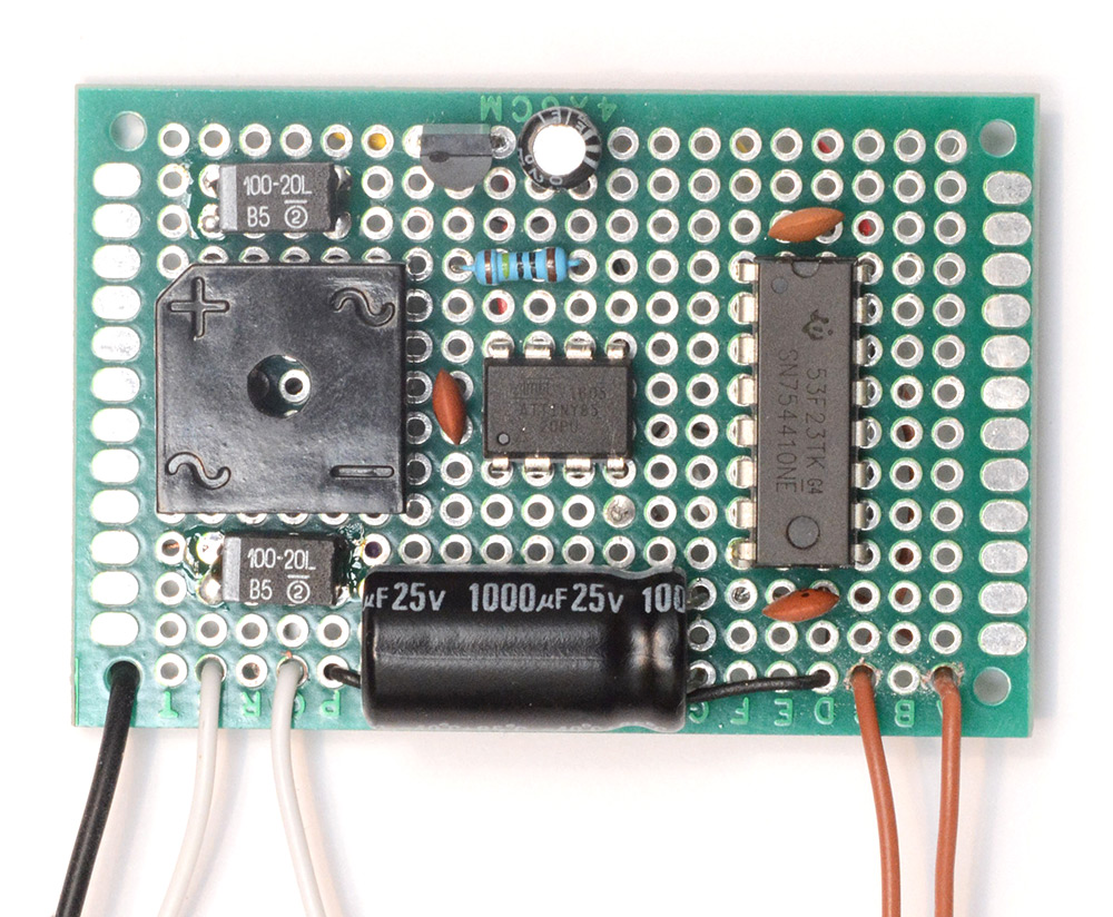
Input on the left and output on the right. I used a single component diode bridge but it makes no difference if you build it from discrete parts. Those very small tantalum 100uF capacitors were left over from a previous project.
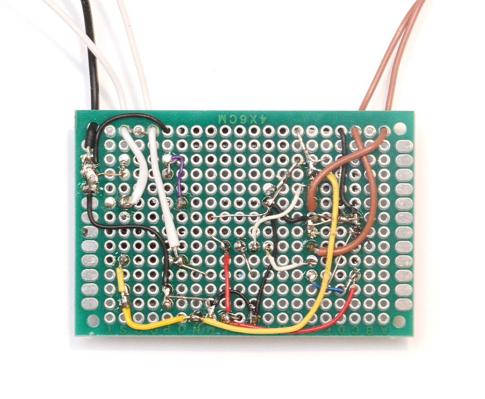
As usual, I built and tested the circuit first, then drew the schematic later.
Note that the differential PWM output of the ATtiny will be "fighting" itself as it reverses the polarity of the motor continuously. For a more advanced way of driving the motor, it's possible to construct a 3-level PWM which modulates the output with an off state, in addition to the two polarities. I figured that if we need to do this I could adapt the circuit later, either by more advanced software (setting both pins high, or both pins low, would send no current through the motor) or by doing something clever like generating a lower frequency output and sending it to the enable pin of the H-bridge. However after constructing the circuit I found the simple way of driving it worked just fine.
Experiment One
The difficulty in debugging something like this is that it's really hard to tell if the clock is ticking correctly. For a start, there's a certain amount of jitter introduced by the mechanical flip-digit display, simply because of the manufacturing tolerances of the digits. But more importantly, we expect there to be about a minute of variation in the phase of the 50Hz signal, and I don't have another synchronous clock to compare it with. So even if our circuit works perfectly, we have to wait at least a day or so before we can confirm it.The ATtiny's Timer0 is set to count the rising edges on its input pin, and an interrupt fires when it reaches the compare value. The value is set to 4, since the zero-state consumes an edge, so the interrupt fires every five rising edges.
Timer1 is used to generate the differential PWM output. The PWM frequency was chosen to be around 36kHz, slow enough to minimize switching loses but fast enough to be outside of human hearing.
For amusement and investigative purposes I first tried an extremely simple program that equates to a PLL with no feedback and no filter. We generate the 60Hz wave based on our internal clock, and when the interrupt fires, we zero its output phase. The frequencies don't quite match, but the total number of cycles is correct.
It's times like this I do yearn for a modern scope with digital storage. Trying to scope such a low frequency waveform is hard because it's outside of the working range of the phosphor. I ended up shooting longish exposures of the scope screen and looking at the images. In the following pictures you can see the discontinuity – I've exaggerated the frequency difference to make it more obvious.
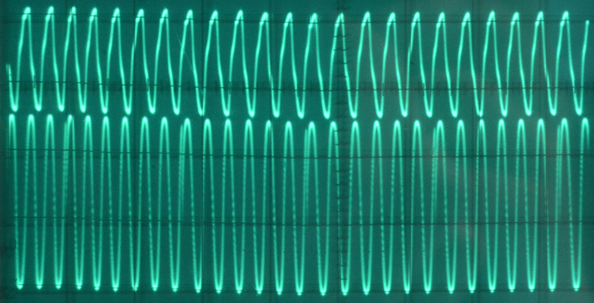
The top trace is the 50Hz waveform from the mains (I'm actually just holding the probe with my hand). The lower trace is the output of the ATtiny, which is being scoped through a low-pass filter. Here's a closeup of the discontinuity:
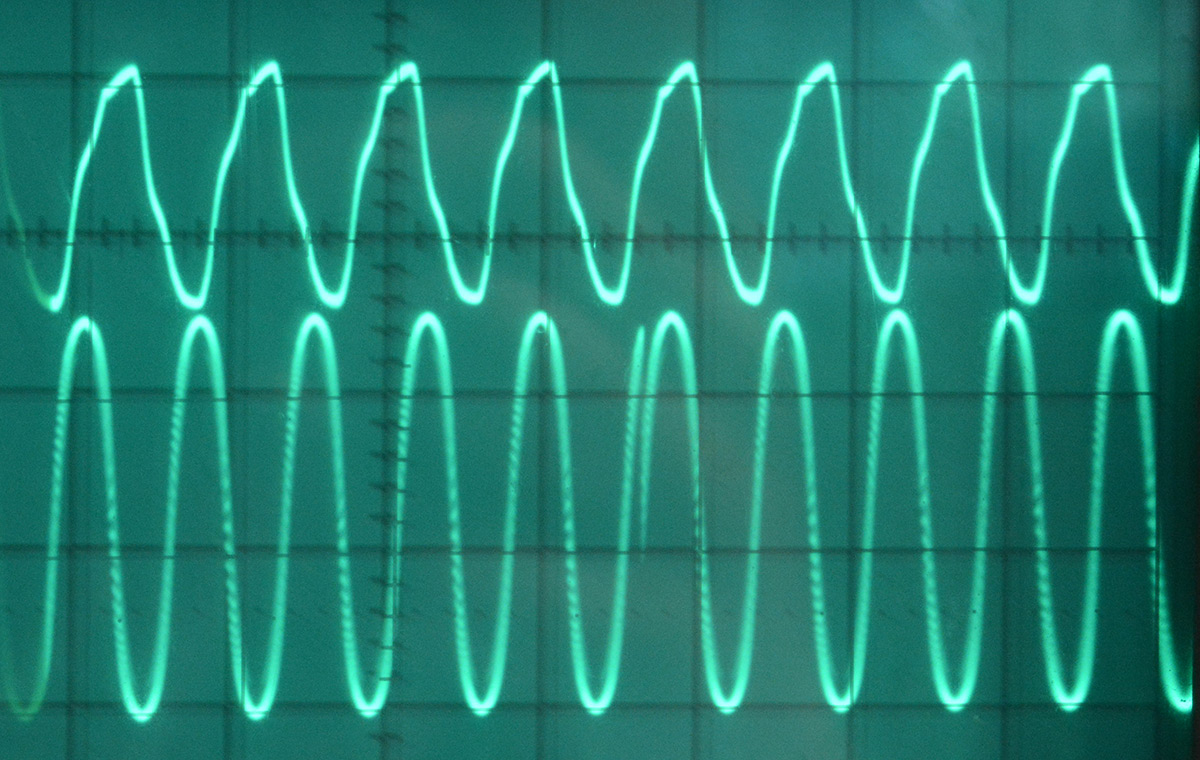
So, it's generating six cycles for every five that come in, but the waveform is horribly distorted. How will it perform? Surprisingly well, and the clock seemed to keep reasonably good time. I left it overnight and found that the next day it had lost about a minute, which is still within the extremes of the expected drift, but by the end of the second day it had lost two minutes. Presumably at the points where the frequencies were most different, the motor was occasionally skipping a step.
Obviously this simple approach isn't sufficient, so let's try it properly.
Experiment Two
The sinewave lookup table is 256 bytes. The ATtiny is running at its default of 1MHz, so for 60Hz output we need to advance the table pointer once every ~65 cycles. I used my usual technique of setting the high byte of the memory pointer to the table, and leaving it as a constant, only incrementing the low byte (ZL). This pointer low byte is then used as the third byte of a 32-bit fixed point counter. The lower two bytes are the fractional part, and the highest byte counts the total number of cycles.So, this gives us a 16-bit value we can add to the 32-bit number to finely control the output frequency. In the interrupt, which is fired every 5 cycles of the input waveform, we check if our number of output cycles is more or less than exactly 6, and adjust the phase-increment value accordingly.
The "filter" is that we check if the phase of the input waveform lines up with the phase of the output waveform, and if they're within about 10%, we lock them together. Without this step, the output wave jumps all over the place before the lock is acquired.
There is a subtlety here to watch out for, since we are using the pointer as part of the same counter for how many cycles have taken place, we cannot simply zero it at the end of the interrupt. Instead we need to remember the phase of the output wave at the end of the interrupt, and work that into our calculation at the start of the next interrupt.
I hope that explanation is reasonably clear. The end result is that the output wave runs freely until it locks in step with the input wave, then the discontinuity smoothly disappears as the frequencies line up with each other. This process (from cold) takes about one second, and from there the wave should track both frequency and phase of the input correctly without any perceptible distortion.
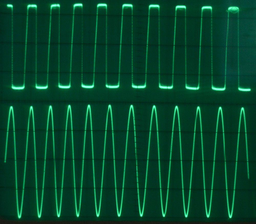
In the above image, the top trace is a scope of the ATtiny's T0 pin, where we can see the effect of the clamping diodes. The lower trace is again a low-pass filtered probing of the PWM output. The apparent waviness of the traces is an artefact of the fact I didn't put the camera on a tripod. This was a ¼ second exposure, and was subject to camera-shake. But we can clearly see a distortion-free sinewave where every six cycles aligns with five of the trace above. Excellent!
The circuit was left to run for a few days, and I periodically checked on its deviation. Happily, it varied between being fast and slow, and remained within about ten seconds of the correct time, which is well within the expected jitter. I also found, in my very subjective assessment of the situation, that this version generated less heat than the first attempt. I suppose with a stable frequency all we're doing is keeping the motor at speed, whereas in the first experiment, with the discontinuity every six cycles, it was constantly trying to speed up and slow down.
This was an enjoyable, mildly pointless, mildly educational project. I should do more of those.
Source Code
I have put a repo up on github, but since it's so short I will paste the code here too:.include "tn85def.inc" rjmp init .org 0x000A ; TIMER0_COMPA cp ZL, r21 cpc r20, r22 brcs slow fast: sbiw Y, 5 rjmp endint slow: adiw Y,5 endint: clr r20 cpi ZL, 30 brcc far1 clr ZL far1: cpi ZL, 256-30 brcs far2 clr ZL far2: mov r21, ZL reti init: ; Timer1 - Differential PWM output on PB0 and PB1 ldi r16, 0b00000011 out DDRB,r16 ldi r16,(1<<PLLE|1<<PCKE) out PLLCSR,r16 ldi r16, (1<<PWM1A|1<<COM1A0|1<<CS12) out TCCR1,r16 ldi r16,128 out OCR1A,r16 ldi r16,255 out OCR1C,r16 ; Timer0 - Count waveform cycles on PB2 ldi r16, 1<<WGM01 out TCCR0A, r16 ldi r16,(1<<CS02|1<<CS01|1<<CS00) ; Clock source = T0 rising edge out TCCR0B,r16 ldi r16, 4 out OCR0A,r16 ldi r16, (1<<OCIE0A) out TIMSK, r16 ldi ZH, high(sineTable*2) ;const clr r0 ; const ldi r22, 6 ; const clr r20 ; YH:YL is used as fractional phase increase ; Main loop takes 10 cycles, lookup table is 256 bytes, target frequency 60Hz, CPU is approx 1MHz ; Starting value = (2**16) * 10 / (1e6/60/256) = 10066 ldi YL, low( 10066 ) ldi YH, high( 10066 ) sei main: add r18, YL adc r19, YH adc ZL, r0 adc r20, r0 lpm r16, Z ; 3 cycles out OCR1A,r16 rjmp main ; 2 cycles .org 0x80 sineTable: .db 128,131,134,137,140,144,147,150,153,156,159,162,165,168,171,174 .db 177,179,182,185,188,191,193,196,199,201,204,206,209,211,213,216 .db 218,220,222,224,226,228,230,232,234,235,237,239,240,241,243,244 .db 245,246,248,249,250,250,251,252,253,253,254,254,254,255,255,255 .db 255,255,255,255,254,254,254,253,253,252,251,250,250,249,248,246 .db 245,244,243,241,240,239,237,235,234,232,230,228,226,224,222,220 .db 218,216,213,211,209,206,204,201,199,196,193,191,188,185,182,179 .db 177,174,171,168,165,162,159,156,153,150,147,144,140,137,134,131 .db 128,125,122,119,116,112,109,106,103,100,97,94,91,88,85,82 .db 79,77,74,71,68,65,63,60,57,55,52,50,47,45,43,40 .db 38,36,34,32,30,28,26,24,22,21,19,17,16,15,13,12 .db 11,10,8,7,6,6,5,4,3,3,2,2,2,1,1,1 .db 1,1,1,1,2,2,2,3,3,4,5,6,6,7,8,10 .db 11,12,13,15,16,17,19,21,22,24,26,28,30,32,34,36 .db 38,40,43,45,47,50,52,55,57,60,63,65,68,71,74,77 .db 79,82,85,88,91,94,97,100,103,106,109,112,116,119,122,125