
Oscillator Calibrator
6 Feb 2020Progress: Complete
The internal RC oscillator on an ATtiny is reportedly calibrated to within 10%. This is an embarrassingly awful tolerance, and suggests that timing-critical hardware such as UART cannot be trusted to work when running on the internal oscillator.
Like most people, I've assumed this tolerance to be nonsense and in reality the chips are calibrated to much finer amounts. But due to the unfathomable success of my Precision Clock Kit I've spent the last few months flashing and testing hundreds of chips, and to my utter astonishment as many as 1 in 5 ATtiny chips fail to decode UART correctly.
My growing pile of "unusable" ATtiny chips is one thing, but the problem I really want to tackle is the uncertainty. Is my stock of 25 chips enough to fulfil 20 orders? I'm sick of not knowing the answer before individually testing them.
The OSCCAL register lets us trim the internal oscillator to within 1% of target frequency. You would expect the manufacturer to provide a routine of some sort to do this for us, or at least for there to be a standard program within the AVR community to perform the calibration. Eventually my frustration with the lack of a straight-forward fix for the problem crossed that threshold into do-it-all-myself territory.
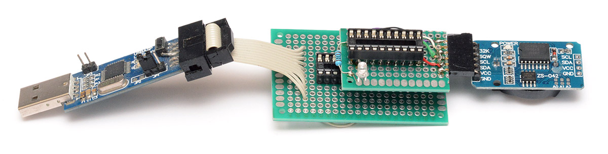
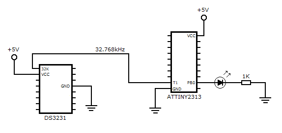
The circuit above is a stack of sockets with multiple purposes. The lower board is my ATtiny flashing arrangement, the USBASP pins are splayed out to provide an ISP connection to the chip, and a crystal is fitted to ease the process of first-time flashing. The upper board attaches a DS3231 real-time clock module. This was originally soldered together as a daughter-board for the precision clock, to improve the behaviour when it loses GPS signal. In this application, we're only using one pin, the 32kHz output.
Be very aware that there are two types of DS3231 RTC. The DS3231SN is the original, which has a claimed accuracy of ±2ppm. It operates by measuring the ambient temperature and switching a capacitor matrix in and out of the loading on the crystal, to maintain a fixed frequency. The DS3231M is a newer, cheaper chip which uses MEMS technology. The MEMS oscillator runs at a high frequency and is divided by a number derived from the temperature sensor, so the seconds pulse is produced correctly and ticks within ±5ppm. But the auxiliary 32kHz output is not temperature compensated and in my experience is way off the mark. Many sellers make no distinction between the chips when they're sold on these little breakout boards, but for this application the DS3231M is useless.
Lastly there's an LED on pin PB0, to visually indicate the state of the calibration.
Note that the calibration may give different results at 5V compared to 3.3V, so run at the appropriate voltage for the intended application.
The calibration procedure goes something like this:
- configure timer 1 to be clocked by the external pin T1. Enable the interrupt at timer overflow, i.e. 65536 periods, or every two seconds.
- let the main loop run freely, counting the number of cycles elapsed
- at the interrupt measure the error amount in the elapsed cycles, and adjust OSCCAL in the right direction
Every time we adjust OSCCAL, we keep note of the direction we're changing it in. At the point where the direction changes, we know we're on the boundary of the ideal value. We let it run again until we've got two direction changes, and from there we can look at the individual errors, and pick the best possible value.
By starting with the value loaded into OSCCAL at the factory, it only takes a few iterations to hit the ideal value, but if we wanted to speed it up we could change the overflow interrupt to be a compare match, and run at maybe half-second interrupts, probably without losing any accuracy.
Once it's finished the calibration, the value is written to the EEPROM and the routine flashes the LED to signal it's complete. It's customary in many situations to set the first byte of EEPROM to be the new calibration value, but when it comes to loading this value, it's important to check it's valid and not some erroneous number. In my case, I'm only ever using the EEPROM for this purpose, so it only needs to check that it's not erased (0xFF). If there's a risk of other data being written to it*, you could add additional checks such as writing a magic number before or after it.
(*A classic example is a reset or fault condition while the application is writing to the EEPROM. It's quite possible the target address becomes zero, but the write continues, so the value at address 0 in the EEPROM gets overwritten.)
Finally, in the makefile, after running the calibration we need to ensure that it stays put by writing to the EESAVE flag in the high fuse byte. In my case that's a value of 0x9F.
The source code and compiled hex file for ATtiny2313 are available in the PrecisionClockMkII repo, both here and on github.