
MIDI Music Box
17 Mar 2018Progress: Complete
There are two ways to put MIDI files in your music box: the easy way, and the hard way. I tried both!
Background: the paper tape
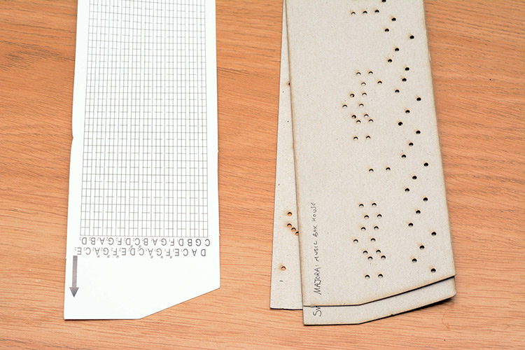
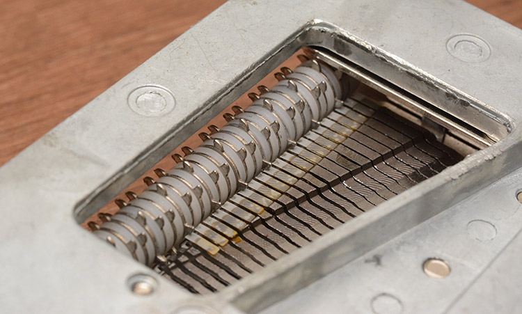
This is the bit I didn't build. A ready made music box mechanism with 30 tuned tines to its comb, and blank paper tape for you to punch your tunes into.
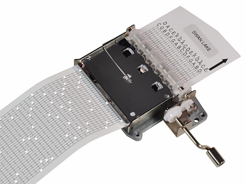
I really wonder how many people have actually gone to the trouble of punching an entire tune into the tape. Few things could beat it in terms of tediousness.
Midi To Moshi
It was the work of an afternoon to concoct a script that takes MIDI files as input and spits out .mdr vector files – the format used by MoshiDraw, that drives the dirt-cheap laser cutter I have.This amounted to taking the script I used to transform MIDI files for playback on the ATtiny85 (itself ultimately a butchered edition of jasmid) and mangling it together with my SVG-to-Moshidraw script.
On the off chance that someone else out there has a laser cutter with Moshidraw 2015 and also a 30-note punched-card music box mechanism, the script is available for your perusal here.
It was a fairly obvious decision to cut out the outline of the tape too. Trying to line up the laser onto an original tape would have been a nightmare (and also, we would have quickly run out of them). But, perhaps a development would be to unplug the stepper motor for one axis and connect a roller in its place, that would let us feed the whole paper strip through regardless of its length.
The 30 note scale is not fully chromatic, only the middle 1½ octaves are, and the rest give you some extended range for certain keys. The lowest note is labelled a C, so I went with that, but by the sound of it the whole labelling scheme is a fifth away from what the box produces.
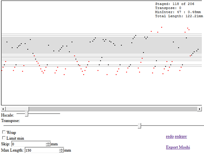
With the lowest and highest notes only provided for certain scales, the need to transpose a tune before committing it to paper is evident. The midi-to-moshi tool visualizes which notes will be played by overlapping them on the grey area (the notes available on the music box) and highlighting the notes outside of this in red. Since there's a chromatic region, we have the option of jumping these up or down by an octave if it's important that they sound, but in many cases this can weirdly distort the melody, so it's not always a good option.
There's also an adjustment for horizontal scale. I didn't quite work out the minimum possible distance between notes of the same pitch, but it's somewhere around 8mm. Closer together than that, and the second note won't sound.
As demonstrated in the video, these laser cut paper tapes worked brilliantly, except for the fact that I had to cut them out in <30cm lengths and tape them together. That tape was ultimately the demise of the first mechanism: the thickness of the taped part adds a lot of resistance to winding the handle, which is why eventually the teeth on the pinion gear stripped out.
Left with a broken music box mechanism, I embarked on the more daring journey.
Imagining a Mechanism
There are many concerns that face us. The very first question: what will provide the motive force to pluck the metal comb? Solenoids would be best, in a sense, because they are essentially silent. Just an electromagnet that pulls a metal rod, with a spring to return it to place. Buying thirty solenoids would be quite expensive, although there's the possibility of making them ourselves. They also need really beefy power supplies.But more of a concern is how we can squeeze all the motors together, because the pitch of the comb means there's just 2mm between each note. Unless we had very, very small solenoids, we'd need to have some kind of linkage system that transports the driving force from the distant motors down into the densely-packed comb area.
Another concern is the plucking action itself. It is not sufficient to simply whack the metal comb, the pluck needs to displace the tine, and then release it. A simple push action could do this, but then, some more complicated movement would be needed to draw the plucking rod back to its original position without hitting the tine again. Conceivably we could just hold it forwards, and pull back, plucking it again, when the next note was needed. But this necessitates equivalent pushing and pulling force, which would imply two solenoids per note – yikes!
I was also against directly plucking the comb because of geometry. The plucking action is at 90 degrees to the comb plane, so we either need to transfer the force through 90 degrees by linkages, or mount the motors above or below it. The sound quality depends enormously on being able to couple the comb firmly to the table it's sitting on (playing the music box in your hand is almost inaudible).
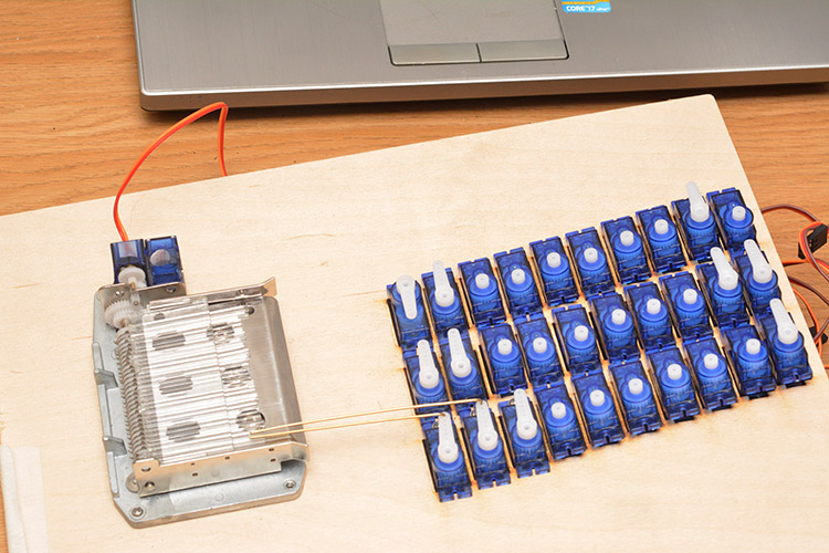
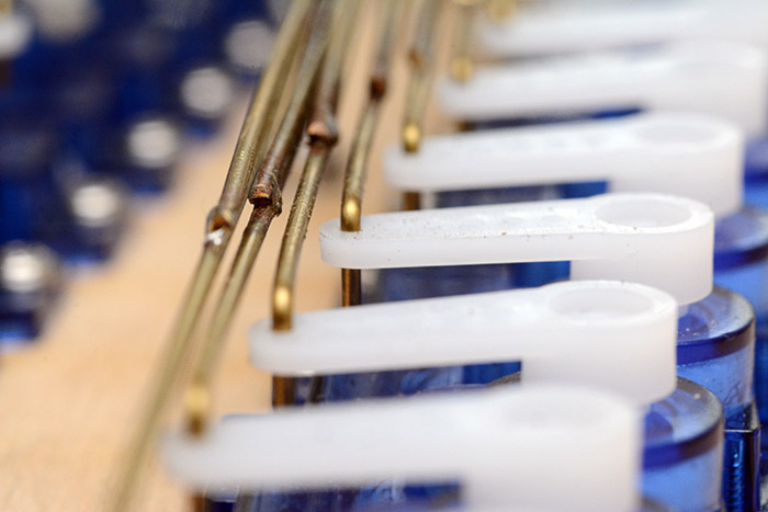
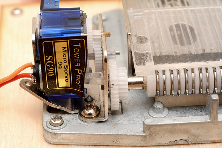
So, solenoids? Stepper motors? Ultimately I decided to go with hobby servos, because the 9g ones are available for £1 each, which includes, of course, positional feedback, and the driving transistors, so they can be controlled directly from a microprocessor. The disadvantages are that the gear train is relatively noisy, and the servo arms still need some mechanism to linearly pluck the tine.
The original mechanism has a series of metal wafers on a shaft with plastic spacers. The shaft rotates, and the wafers are gently dragged around by friction, until the protruding tabs hit the paper tape. When a hole in the paper tape passes above, the wafers can rotate a little more, and from there the hole in the tape will catch the tab and continue to pull it for the rest of the quarter-turn. The tab 90 degrees away from the one being pulled is the one that plucks the metal comb.
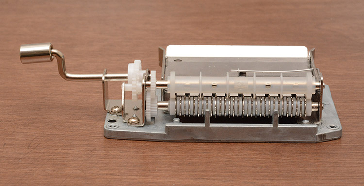
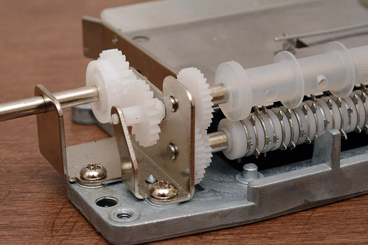
So, if we keep that whole assembly in place, minus the paper tape, assuming the shaft is still driven we can pluck any note with a single forwards action. Using the wafers and friction drive of the original mechanism lets us both turn the force through 90 degrees, and also avoids the double-pluck problem, as the wafers only rotate in one direction.
If you have watched the video, you'll know the arrangement I ultimately went with, but there were many iterations before I settled with that design.
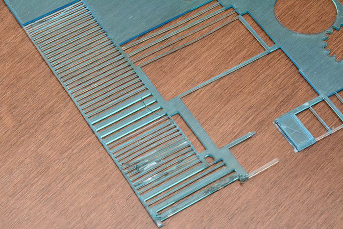
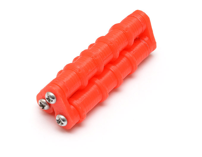
I laser cut plastic fingers to actually do the pushing of the tabs, I used nominally 2mm thick acrylic. The pitch of the comb is 2mm too. So I should have ended up with lengths of plastic which were a perfect 2mm square in profile, but there were a few things that hindered this. The acrylic turned out to be only about 1.8mm thick. Also, there's the kerf of the laser to contend with, which depends on how well it was in focus. And, cutting out lots of fingers next to each other causes the plastic to warm up and deform.
Well, the solution to the first problem is to keep every finger upright, so the uncontrollable dimension (the initial thickness of the sheet) is in a plane that doesn't matter. The second fix is to account for the kerf. This is hard, because if the width isn't spot on the error will accumulate. Because it's only 2mm, I didn't think there was room for any supporting structure between the fingers, so it's only the fingers on either side that hold any given finger in the right place. Well, having cut out a few fingers that were too wide, and a few that were too small, I measured the ratio between their inaccuracies and interleaved them in a ratio to counteract it. I think it was three fat fingers, followed by one thin one, followed by another three fat ones, etc. By doing this I had perfect control of the error. A snagging point is that the fingers now have specific places, so removing all of them means taping them together so we don't lose their order.
The other problem I mentioned, about the plastic deforming due to heat, is easy to compensate for. At the very simplest you could just wait for it to cool down between cuts, or space out the pieces (which is wasteful of plastic), but the best solution is to change the order in which they're cut out. Something like 1, 5, 9, 3, 7... is enough to let things cool down.
Sometimes I feel guilty for being wasteful of acrylic. Not this time.
Metal Linkages
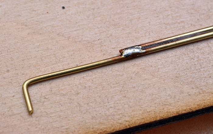
At this point we had plastic fingers that when pushed and pulled back, made a note sound. Now we needed to drive these fingers, in a way that lots of motors don't interfere with each other. I had a rough idea in mind and cut out a prototype.The point about using 1mm brass wire is that it's flexible. The hobby servos move in an arc, and the fingers move linearly. If the acrylic fingers were long enough to be attached directly to the servos, they would probably snap, because they're pretty brittle. There is also the question of height alignment, and the coupling to the servo which needs to be free to rotate. Having brass wire lengths, which are bent to slot into the servo arm, solves both problems.
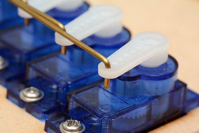
I did as much as was needed to confirm that this mechanism would work with two notes. To attach the brass wire onto the plastic fingers, I used superglue. This amounted to carefully dribbling a tiny bit of glue along the top of the finger and letting the brass lie on top of it. Too much glue, and it would dribble between the fingers and fuse them together. To get a good join the brass has to sit flat, which means a lot of bending back and forth to get it perfectly lined up. My experiments here confirmed that this would basically work, as long as the force was mostly in the right direction.
So. Time to assemble 30 of them?
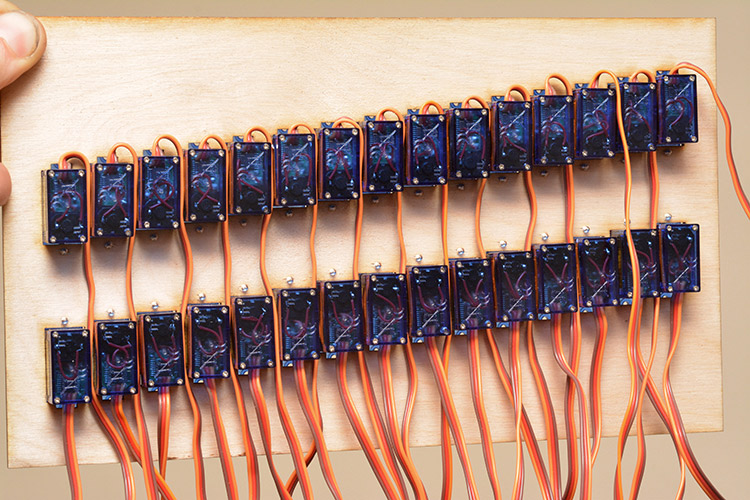
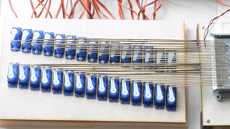
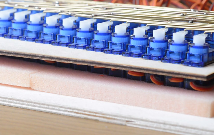
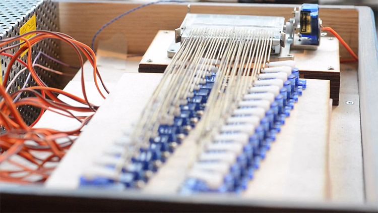
Here's the first full attempt. The laser cutter makes it very easy to position servos in exact locations. I figured it was about three servos wide, if we turn the third one backwards, and then copied and pasted the row ten times, shifting it by 2mm each time. Soon it became apparent that there wasn't much slack allowed in the alignment, since I'd hoped to have all of the wires gently bending inwards, but really they needed to be as straight as possible. Not only so that they don't bend and deform as they're pushed, but also so they don't crash into the wires on either side. Hmm.
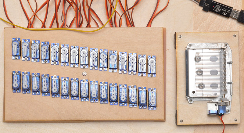
I eventually cut out the alignment shown in the final thing, with two columns of fifteen servos. They're facing opposite directions, and stepped at 2mm like before. This means the outermost hole in every servo arm is directly in line with one finger. (It's best to use the outermost hole, to minimize the lateral motion due to it being an arc, although this does reduce the torque available.)
The 1mm diameter brass wire came on a reel, and so before it can be shaped into linkages, it had to be straightened. I started off doing this between my thumbs. It is a strange and useful skill to be able to straighten wire between one's thumbs, and it takes a fair bit of practice to get the hang of it, so I take pride in being able to do it. But, after the first few metres, my thumbs were sore as heck!
I do, believe it or not, own a 3D printer. It's cheap and cheerful and I barely ever use it. Not because I fundamentally dislike the lack of hands-on craftmanship in 3D printing, but because it's so damn slow. I own both a laser cutter and a 3D printer, and the laser gets used at least once a week – the 3D printer hasn't been used in months. So, to try and balance this out a bit, I figured that someone must have designed a wire-straightening jig I could print out. And they had! A few hours later (during which, I had continued to straighten the wire by hand) I had a 3D printed wire-straightening jig.
And it didn't work, at all. Must have been designed for a much thinner type of wire. So, I ended up straightening the rest of it all by hand anyway.
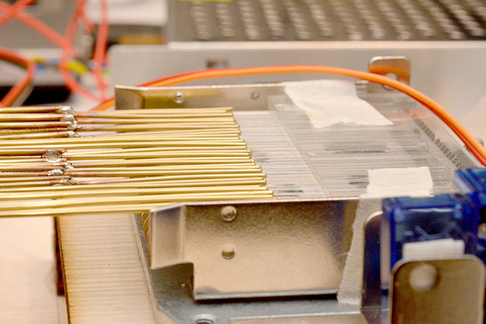
A problem we faced now was that the very furthest servos had such a long bit of wire that they're too flexible, and were likely to buckle instead of pushing straight. Anticipating the problem, I soldered reinforcements onto the longest wires to stiffen them. This was, to put it mildly, slightly tedious.
But even with only four or five mechanisms assembled, I could see this design was going to work, which was incentive to complete the rest. And while we're at it, there's the rest of the electronics to worry about.
The plastic fingers are all held in place by a framework made of yet more laser cut acrylic. As you can maybe see in this next picture, the top piece is slid in place under rails that were superglued in place. The masking tape here is used to stop the plate sliding back and forwards. With the linkages glued to the fingers, sliding the plate out is the only way to dismantle the mechanism. Later, I tightened the rails a bit so that the tape isn't necessary.
Control Board
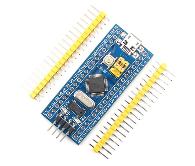
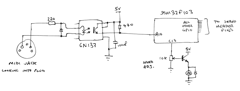
Servos are controlled by a form of pulse-width modulation that's on the order of milliseconds. So, we could potentially use a tiny microcontroller and a bunch of port-expanders or multiplexers. But things are much simpler if we find a microcontroller with at least 31 GPIO pins – one for each servo, and one for the MIDI input. Since I was playing with one not long ago for a different synthesizer project, and I appreciated how incredibly cheap it was, I went with one of the STM32F103 boards you can get for pennies on eBay.
Given how popular it is, I suspect there's a bunch of friendly IDEs available to work with this thing that handle everything for you. So I probably made life hard for myself by starting with arm-gcc and setting up the toolchain almost from scratch. But that's a problem for a different project page. The software here should be very simple. Just wait for MIDI note-on messages, and send the relevant servo through a timeline of positions.
To my surprise, the software turned out to be something of a nightmare. I do prefer assembly for embedded programming, but no one seems to do that when it comes to ARM cores. So I stuck to C, and infuriatingly one of the main problems I had turned out to be an unexpected compiler optimization that was affecting the timing in an unpredictable way.
I initially had power supply problems, since an individual servo can draw a lot of current, maybe half an amp or more. And we've got thirty of them. Upgrading the power supply to a 60W 5V supply seemed to fix a lot of issues, but still some problems remained. I eventually gave the thing a 150W 5V power supply, just to put my mind at rest that it's not the power supply that's the problem.

It's surprisingly easy (and not particularly expensive) to get hold of this type of mains power supply that steps down to low voltage and high current. They're probably used a lot for things like LED lighting installations. The 30 Amp module cost about £15.
I doubt the thing ever draws anywhere near 60W, let alone 150W, but it's all about peak draw rather than averaging. I was tempted, a little at least, to add a capacitor onto each servo, as close to the motor as possible. While this might have fixed it, it would mean a lot of tedious work compared to just getting an overkill power supply.
To be honest one of the main improvements was when I stopped putting servos to sleep when they're not in use. If you stop sending them pulses, they'll go dead and effectively use no power. Inherently you'd think that it would be a good thing for them to be sleeping when not in use, there's enough friction to keep them still and there's no lag when it comes to powering them up again. But there is a problem when all your servos are off and a big chord comes in, because that's a massive sudden draw on the power supply and it might not respond so quick. Having them all on all of the time means the change in current draw is much less drastic when the mechanical load changes.
It also helps to keep them warm. I found that the torque available (and noise produced) depended on temperature. On a cold day the servos can't push as much – or more accurately, take longer to reach their position under a fixed load. That means the timelines for their motion need to dwell at certain places for a little longer, but the performance improves as it warms. It also depends greatly on the individual servos, there was a huge variation between them. However, with the servos always powered up, they are likely to stay warm once they've reached operating temperature.
Talking of timelines, as I mention in the video, originally I had a much more complex motion in mind, but ended up cutting it to be as short as possible to minimize power usage and reduce dead time before the note can be repeated.
The last servo
One more motor is needed, to do the job that was originally done by the handle. Our choice of reusing the wafers for the mechanism means they need to be driven whenever a note sounds to reset the wafer position. Previously this was done by the same shaft that rotated to push the paper tape onwards.Since I'd bought the servos in bulk it made sense to use the same again but modified for continuous rotation. This is pretty easy, you just unscrew the base, pull the thing apart, cut the limiting bits and decouple it from the potentiometer. I got rid of the control board too since we just want it to run endlessly.
There's a whole train of gears inside each one, and to my delight one of those gears meshed perfectly with the remaining gear train of the damaged music box mechanism. It doesn't provide much torque, but it doesn't need to since we're no longer driving the paper tape. Then there comes a compromise: how fast should it spin? The faster it spins, the quicker we can play notes in succession, but the louder the motor noise will be. I decided to concoct a simple adjustable-speed drive circuit in order to defer the question for later. Here's what I came up with:
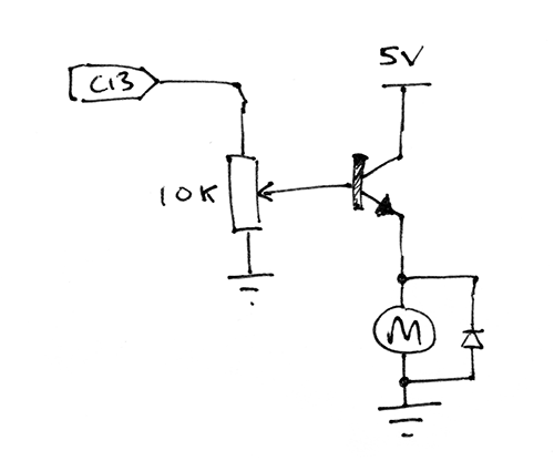
Though I planned to drive this continuously, that would get a little annoying and probably wear it out, and we do have one spare pin on the microcontroller. It has 32 GPIO pins, 30 of which are running servos, and one is receiving UART data. The last one (Pin C13) is hard-wired to the on-board LED. That should do nicely, and also means the LED blinks as notes come in (or more precisely, turns on when notes stop coming in).
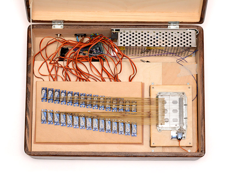
The circuit board, built on protoboard, just breaks out all the GPIO onto header pins with power rails for all the servos. The only other circuitry is the speed controller for the last servo motor and the optoisolation for the midi input.
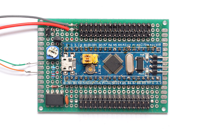
Note: it was a mistake to space all the pins that close together. The plugs on the end of the servos are very slightly wider than they ought to be, and so having fifteen of them directly adjacent causes a lot of problems plugging it all in. It was possible to jam them all in, in the end, but it means that hot-swapping a servo is an unpleasant ordeal.
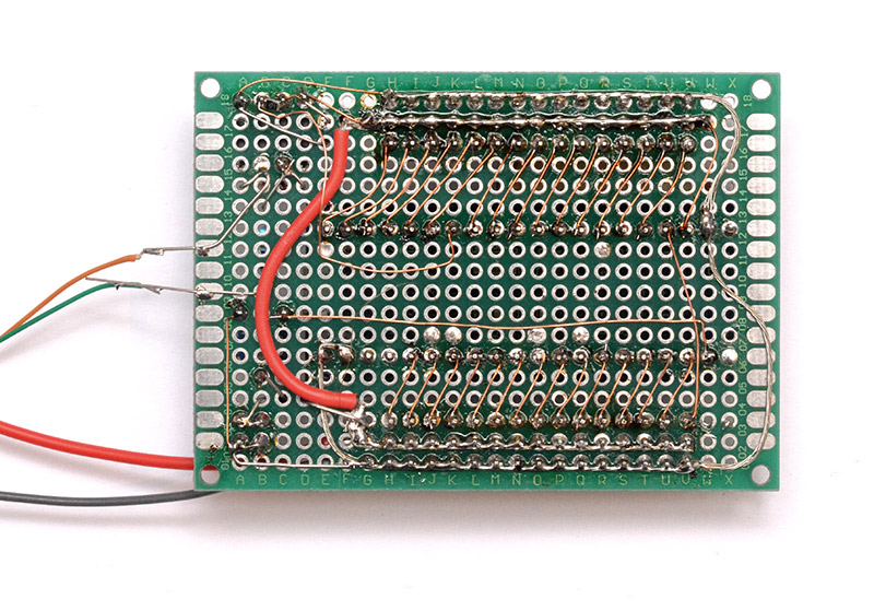
These shots were taken before the final construction. I ended up adding even more redundancy to the power rails, given that there could be 30 Amps pumping through there.
Calibration
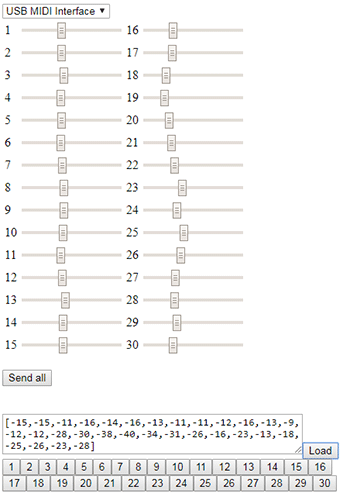
Thinking back to this stage of construction, I can't believe I actually thought there might be a fixed position value that could be sent to a servo and have it predictably go there. I sent the 50% position command to every servo and found there was as much as 30 degrees variation from one servo to the next. Not only that, but it varied a fair bit between powering up the same servo (although, in retrospect, this was likely due to power supply issues and software problems). The servo arms can only be attached at certain positions where the splines line up, so the only way to get all the arms to point the same direction is to send each servo a different number.To do this in a way that didn't induce insanity meant making an automated script. There's no EEPROM or non-volatile storage on the chip, but we can hold the numbers in RAM and once they're finalized write them to the flash. I added a MIDI decoding step which both updated the calibration in RAM and moved the servo to that position. Then, a program on my laptop can have a slider that moves the servo in real time to the right position.
The MIDI message I chose wasn't SysEx as you might expect, because that's a real hassle. Instead I chose probably the least-used MIDI message ever: polyphonic aftertouch on channel 10. Polyphonic aftertouch is already pretty rare, but having it on a channel dedicated to drums makes no sense at all. The status code is then 0xAA. This lets me always be ready to recalibrate, but without having to fear that a random midi file could mess it up. And the fear would be genuine, because there's enough power here for the whole set-up to tear itself apart. On multiple occasions I accidentally sent all servos to their zero position, which means they rotate far enough to rip the finger linkage apart. Quite a stressful thing to witness!
The calibration tool, obviously is a javascript monstrosity with 30 html5 sliders. After using it, I can copy and paste its text output straight into the C code for permanent storage. The process like this is pretty quick. After the fourth or fifth calibration, the set up and the software became stable enough that I haven't had to calibrate it since.
I did once (erroneously) think that it'd gone out of calibration again, when I found half of the fingers were too far forwards and the other half were too far back. This scenario suggests that every servo has gone to a lower (or higher) number systematically. But it wasn't that, in fact it was entirely mechanical: I'd knocked the support board for the servos and it had rotated around the central bolt.
The reason I'd only tied it down with one bolt was to try and cut down on noise. The servo plate is mounted on foam, with just one mechanical link to hold it in place. Perhaps two bolts would have avoided this, but would that have provided as good decoupling of sound?
Sound Quality
I had, as you can see, mounted the main servo board completely separately to the rest of it on a layer of PU foam. There's a single bolt in the middle to maintain the position, which is just loosely fitted to avoid coupling too much. It's really surprising how much of a difference having a good mounting makes to the sound quality. If you pick up an unmodified music box mechanism and wind it in your hands it's almost inaudible, but pressing it against a wooden table gives the sound a substantial volume.
Similarly, pressing the midi mechanism against a table greatly improves the sound quality, but it really leapt forwards after I added a sound peg. The main mechanism is supported by four legs (which were built out of the rectangular cutouts produced by all the servo holes). Jamming a fifth leg in the middle, much like the way a violin has a sound peg under its bridge, gave an amazing improvement to the tone.
While playing around with this I tried wedging a piezoelectric plate between the sound peg and the board. It was one of the cheapo 20p piezo buzzers you can get, but it functions perfectly well as a contact mic. There's a bit of an art to placing a contact mic, the sound it picks up varies a lot on where it's placed, and the other thing to be careful about is the amplification. At first I plugged it straight into the line input of my Zoom H2N, which has an input impedance of a few kOhm. This gave a really poor bass performance because the output impedance of a piezo buzzer is negligible. Plugging the mic into my headphone amp first gave a much better performance, since the input impedance there is the 50KOhm input attenuator.
In the picture above, the thin purple/blue wire at the back is the lead to the contact mic. Since it's a differential signal (and a tiny one, too) it's important to have a very tightly twisted pair, or there'll be loads of noise picked up by the amp circuit.
The only annoying thing about this contact mic is there's a buzzing noise it picks up. I think it's the plastic tabs that are on the backs of some of the tines to stop the wafers dampening them. The buzzing isn't audible at all to an ordinary listener. Still, the convenience of the contact mic is worth it, since for shooting the video I could rotate the box and move the camera and not have to worry about varying sound quality.
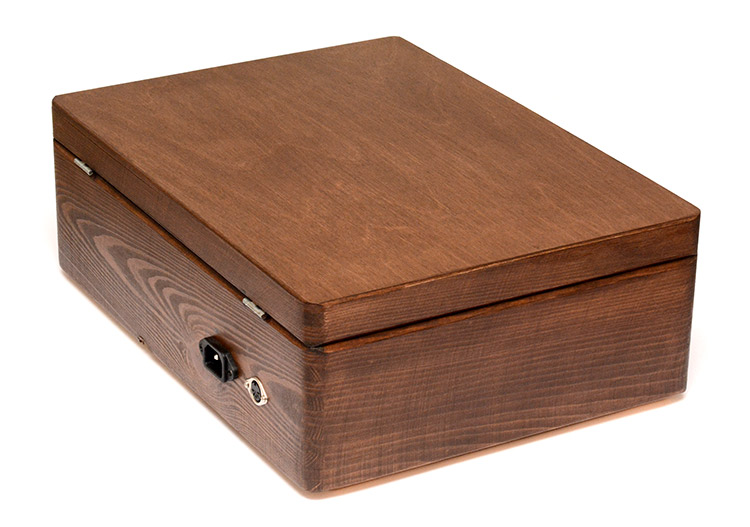
The Box
For the enclosure I didn't put in too much effort. I found a wooden box of approximately the right size, built a little frame inside it to hold the mechanism, and stained and varnished the outside.

Potential improvements
Belt drive
With the foam mounting for most of the servos being pretty effective, it'd be neat to have the last one mounted there too. A belt drive is the obvious solution as it would be poor at transferring vibration. I do have a collection of small toothed belts (pulled from printers and scanners of course) but they're all far too long for this application. Unless I can come up with a reliable way to splice toothed belts, we'll need to invest in a fresh one with the right dimensions. I don't know where you can buy tiny toothed belts, all I could find were the type you get on 3D printers, which are both too wide and not intended for continuous rotation (the join wouldn't be able to fit through the pulley).There's always the option of an elastic band, but I get the feeling that we could sink a lot of time into adjusting the pulleys there and still not have a satisfactory result.
Auto Transpose
Many midi files are in the wrong key to make the best use of the notes available. It's easy enough to automatically wrap notes by octaves to squeeze everything into the chromatic region, but this often distorts melodies and in most cases won't give as good a result as transposing everything. The problems with implementing auto-transpose are myriad, though. Without an interactive display, like the Midi-to-Moshi converter at the top, we can't visualize the playable/non-playable overlap and so we can only go by the numbers. But even going by the numbers is unfeasible if we're trying to deal with live midi data.There are a few possible solutions. One is to constantly remember the notes played on the music box, then when an "adjust" signal is received, calculate the best transposition for the recorded notes. Then, we would play the midi file a second time and it would sound in the right key. This is kind of ugly, though, having to play the entire file for it to be analysed, and then having to reset everything when we want to play a different file.
Another solution is to physically add a control onto the music box representing transpose. Visual inspection of the servos could show how successful this adjustment is. We've run out of GPIO available, but the task could be performed by a second microcontroller that preparses the midi data.
The third solution is the one I was basically doing anyway – analyse the file on a laptop before sending it. We can do input and output using web-midi, so it'd be possible to have the neat midi-to-moshi visualization running in realtime.
Timing Calibration
When midi files play, there's a kind of characteristic timing error in the sound output because of the differences from one servo to the next. Although we've calibrated it so that each note can sound, some servos are stronger than others, and some tines take more force to actuate than others, so each note sounds at a different point in the timeline. We could add a second calibration, a millisecond timing offset, so that the lag of any given servo is normalized and midi files play perfectly in time. The downside is that this would increase the overall lag, although not by much.
USB port
I've demonstrated the music box many times now, and that usually involves plugging a midi keyboard into it for some realtime fun. This means I need to power the keyboard too, and most keyboards can be powered by USB. A USB-A socket on the box would let me have a self-contained instrument. It would also be good for, you know, charging your phone at 30 Amps, maybe. The problem is that there's an expectation then: we'd want the USB socket to also function as a USB MIDI host. I'm not ruling this out, it might even be possible to use the STM32F103's USB port in OTG mode to do this, I've not looked into it.
SD Card
Standalone playback of MIDI files would be great. An SD card slot, so it can behave like a jukebox, would be fantastic. Probably easiest to build a secondary device which reads the card and spits out MIDI.
Plate Reverb
We have successfully mounted a microphone to the device. It could potentially act as a transducer, too. I am interested to know how the music box's metal comb would behave when used as a plate reverb. Each of the tines would oscillate at their pitches, so would the overall effect be something like a vocoder? Definitely worth investigating!