
MIDI on the ATtiny
27 May 2015Progress: Complete
Yeah, yeah, I'm in love with MIDI. But I've never done any really low-level stuff with it, so I thought it was time to take our relationship to the next step.
I also just discovered Atmel's ATtiny series. I mean, I think I've known about it at the back of my mind for years but I've never played with any of them. Not only are they ludicrously cheap, but they're capable of operating without any external components - just feed it power and you're set. Everything - oscillator, RAM, EEPROM, and flash (program) memory, all in a single package. Wow!
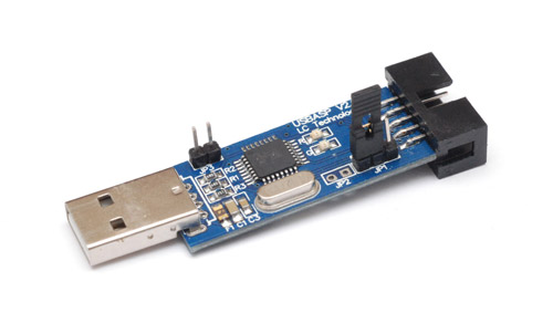
But the real selling point is the availability of low-cost ISP programmers. I remember last time I played with microcontrollers, I swear the programmer cost about £60. This time I got a USBASP programmer on eBay for £1.34 delivered. My whole development environment was up and running for less than the cost of a pint of beer.
MIDI is UART
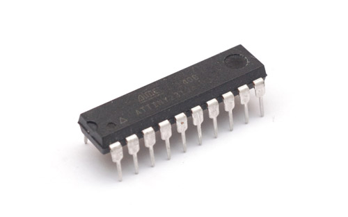
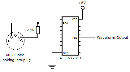
UART is asynchronous serial data, which means there's no clock signal. MIDI is a specific implementation that says the baud rate is 31.25kBits/s to within 1%, and the protocol is 1 start bit, 8 data bits and 1 stop bit.The bytes are either status bytes or data bytes, so 'Note on' would be a status followed by two data bytes giving the note number and its velocity. There's lots of info on the web and I'm sure the reader is familiar with the basics of MIDI. But how hard would it be to build a synthesizer completely from scratch? Most ATTiny chips have a hardware UART port, so to start, let's go with that. Here's a common chip - an ATtiny2313.
In terms of electrical connections, you're supposed to have an optoisolator between each device to avoid ground loops. For reasons which will become apparent later I'll skip this and just connect the data straight to the chip. The line is normally high, and is pulled low when active. It's sent on two wires as a balanced signal intended to go straight into an optoisolator. In fact, one line stays high all the time and the other does all the data. In order to get a clean signal, I found it was best to put a 2.2K resistor between the lines, so that the data line is pulled up when inactive. For these tests, both my MIDI keyboard and the chip were powered from my laptop's USB port, so there's no risk of ground differences.
If we run the chip at a standard 8Mhz, to get the 31250 baud rate we conveniently need to divide by 256. Per the datasheet this corresponds to a UBRR value of 15. Other than that, all the initialization is very simple since 8 data bits, no parity, 1 stop bit is essentially the default settings. The init code is:
    ldi r16,0
    out UBRRH,r16
    ldi r16,15
    out UBRRL,r16

    ldi r16,(1<<RXEN)
    out UCSRB,r16

    ldi r16,(1<<UCSZ1|1<<UCSZ0)
    out UCSRC,r16
and to receive a byte, we call this routine:
receiveByte:
    sbis UCSRA,RXC
    rjmp receiveByte

    in r16,UDR
    ret
So how should we turn this MIDI data into sound? The easiest way, by far, is to use a timer in waveform generation mode. Usually, for an analogue voltage you'd use PWM and update the output-compare value at each sample of the waveform. PWM works by toggling an output pin twice during a loop of the timer, and the ratio between the two points where it toggles gives the duty cycle of the output. Usually the upper point is the timer overflowing, or sometimes you use two output-compare values. We can make use of this same hardware to generate a fixed duty-cycle, variable frequency wave by only toggling the pin once during a loop of the timer. This is the technique I used for my games console (which I still haven't written up, because it's enormous). The best bit about it is you can set up the pitch of the note, and leave it at that - it'll continue to sound regardless of what else the chip goes off doing until you specifically change it.
Some AVR chips need a bit of thinking to get them to behave like this, but the tiny2313 has a pretty straightforward set of 'waveform generation' bits to set up this mode. We'll use the 16-bit timer to get the best resolution over the audible range, with a lookup table to turn MIDI notenumbers into timer periods. To initialize, we only need to set the correct pin as output (PB3) and set the COM1A0 bit in TCCR1A. The timer is stopped by default, so to make a sound, we set WGM12 and CS10 in TCCR1B, and the period in the registers OCR1AH and OCR1AL. To stop the sound we set TCCR1B to zero.
It's quite fun, for testing purposes you understand, to send the pitchbend messages straight to the timer period. Most entertaining. But for a playable, in tune instrument we need to make a lookup table for periods. This is easily calculated since we know two things: an octave is exactly double/half the frequency, and there are 12 semitones in an octave, at equal pitch ratios (for equal temperament at least). So a frequency from a note number is just 2(n/12) and to get periods, we divide the maximum timer period (216 - 1) by the frequency. Some offsetting is needed to get it to line up with MIDI's middle C. When faced with a simple thing like this I always turn to javascript, since, assuming your web browser is already open, you're just a single keystroke away from a console. Nothing is more convenient!
A note on the assembler directives '.db' and '.dw' : even though this is 16-bit data, I'm still going to use .db, as it means I can avoid having to think. There seems to be some natural law of the universe that whenever endianess is involved, you'll always get it wrong the first time.
So the program logic is like this: Keep calling receiveByte until we get either a noteon or a noteoff status. We know that both of those are followed by exactly two data bytes, so in their routines we must call receiveByte twice more. For noteon, we need to lookup the period and set it. For noteoff we just clear the timer. One final bit of logic to make it more playable is to only listen to noteoff if the notenumber is the same as the most recent noteon, which makes a run of overlapping notes sound continuously.
Here's the program so far. A monophonic square wave synth in just 82 bytes of code (and a 256 byte lookup table of course). I pulled a trick with the lookup table, since it's small and there's no reason not to: precede it by '.org 256' to align it with a page of the flash, and then we don't need to bother with the high byte of the pointer since it'll be the same for all of the table. Otherwise we'd need to do an add-with-carry on it. You could shorten this further, just load ZH in the init code and have receiveByte load straight to ZL, but we're not in any way short of resources and it's clearer to read like this.
.include "tn2313def.inc"

    ;Waveform init
    sbi DDRB,PB3

    ldi r16,(1<<COM1A0)
    out TCCR1A,r16


    ;UART init
    ldi r16,0
    out UBRRH,r16
    ldi r16,15
    out UBRRL,r16

    ldi r16,(1<<RXEN)
    out UCSRB,r16

    ldi r16,(1<<UCSZ1|1<<UCSZ0)
    out UCSRC,r16


main:
    rcall receiveByte

    cpi r16,0b10010000
    breq noteon

    cpi r16,0b10000000
    breq noteoff

    rjmp main


noteon:
    rcall receiveByte
    mov r20,r16

    subi r16,27

    lsl r16
    ldi ZH,HIGH(musicNoteLookup*2)
    ldi ZL, LOW(musicNoteLookup*2)
    add ZL, r16

    ldi r16, (1<<CS10|1<<WGM12)
    out TCCR1B, r16

    lpm r16,Z+
    out OCR1AH, r16
    lpm r16,Z
    out OCR1AL, r16

    rjmp main


noteoff:
    rcall receiveByte
    cp r16,r20
    brne main

    ldi r16,0
    out TCCR1B, r16

    rjmp main


receiveByte:
    sbis UCSRA,RXC
    rjmp receiveByte

    in r16,UDR
    ret


.org 256
musicNoteLookup:
.db $FF,$FF,$F1,$A1,$E4,$11,$D7,$44,$CB,$2F,$BF,$C8,$B5,$04,$AA,$DB
.db $A1,$44,$98,$37,$8F,$AC,$87,$9C,$80,$00,$78,$D0,$72,$09,$6B,$A2
.db $65,$98,$5F,$E4,$5A,$82,$55,$6E,$50,$A2,$4C,$1C,$47,$D6,$43,$CE
.db $40,$00,$3C,$68,$39,$04,$35,$D1,$32,$CC,$2F,$F2,$2D,$41,$2A,$B7
.db $28,$51,$26,$0E,$23,$EB,$21,$E7,$20,$00,$1E,$34,$1C,$82,$1A,$E9
.db $19,$66,$17,$F9,$16,$A1,$15,$5B,$14,$29,$13,$07,$11,$F6,$10,$F3
.db $10,$00,$0F,$1A,$0E,$41,$0D,$74,$0C,$B3,$0B,$FC,$0B,$50,$0A,$AE
.db $0A,$14,$09,$83,$08,$FB,$08,$7A,$08,$00,$07,$8D,$07,$21,$06,$BA
.db $06,$59,$05,$FE,$05,$A8,$05,$57,$05,$0A,$04,$C2,$04,$7D,$04,$3D
.db $04,$00,$03,$C7,$03,$90,$03,$5D,$03,$2D,$02,$FF,$02,$D4,$02,$AB
.db $02,$85,$02,$61,$02,$3F,$02,$1E,$02,$00,$01,$E3,$01,$C8,$01,$AF
.db $01,$96,$01,$80,$01,$6A,$01,$56,$01,$43,$01,$30,$01,$1F,$01,$0F
.db $01,$00,$00,$F2,$00,$E4,$00,$D7,$00,$CB,$00,$C0,$00,$B5,$00,$AB
.db $00,$A1,$00,$98,$00,$90,$00,$88,$00,$80,$00,$79,$00,$72,$00,$6C
.db $00,$66,$00,$60,$00,$5B,$00,$55,$00,$51,$00,$4C,$00,$48,$00,$44
.db $00,$40,$00,$3C,$00,$39,$00,$36,$00,$33,$00,$30,$00,$2D
Even I am amazed by how easy that was. The world's simplest synthesizer? But not the smallest. One problem with the ATtiny2313 is that it's not all that tiny. Let's step up our game...
The ATtiny85
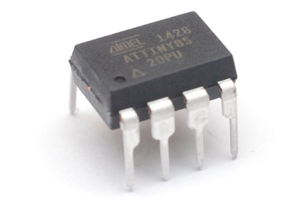
Now this is a little more challenging. No hardware UART suppport, and the timers are only 8 bit. Amazingly, I bought 10 of these chips for £9 including shipping.
The first thing I did when my ATtiny85s arrived was try to recreate the static midi playback I'd got with my games console. Although an 8 bit timer goes out of tune pretty quickly (1% before the third octave) we could keep the lower parts of the lookup table and make use of the clock prescalers. These give us fixed binary divisions of the main clock signal - in other words, we can jump octaves with them. The prescalers are different for each timer, but both can be set within two octaves.
I won't go into too much detail since this isn't genuinely MIDI, but after a little fudging I'd gotten two-channel playback of what started life as a MIDI file. I used the same tactic as for the games console, preprocessing the file into a list of notenumbers and durations for simplicity. The ATtiny85 has 8kB of program memory, easily enough for 5 minutes of chiptune goodness, especially with some simple run-length-encoding. I may post another project page about this. The key thing is that I was setting the note periods something like this:
setNote0:
    push ZL
    push ZH

    ldi r17,0
    subi r16, 12
    brcs sN0Load

    ldi r17, (1<<CS02|1<<CS00)
    subi r16,24
    brcs sN0Load

    ldi r17, (1<<CS02)
    subi r16,24
    brcs sN0Load

    ldi r17, (1<<CS01|1<<CS00)
    subi r16,24

sN0Load:
    out TCCR0B,r17

    subi r16,-24
    ldi ZH, HIGH(noteLookup*2)
    ldi ZL,  LOW(noteLookup*2)
    add ZL, r16
    clr r16
    adc ZH,r16
    lpm r16,Z
    out OCR0A, r16

    in r17,TCNT0
    cp r17,r16
    brcs sN0end
    dec r16
    out TCNT0,r16
sN0end:
    pop ZH
    pop ZL
    ret
The repeated subtraction is essentially a division to find the octave and then set the notenumber. Another thing I found improved the sound was to manually check if the timer was going to overflow as we changed the output compare value, and zero it if necessary. This prevents a glitch in the waveform output.
Software UART
UART is simple enough that a software implementation isn't much longer than the code for the hardware version.I should probably talk about crystals and clock speeds. MIDI asks for the clock speed to be within 1% - but every midi keyboard will probably be sending at far better accuracy than that. In these experiments I'm not using a crystal for the ATtiny chips, just their internal RC oscillator. From the factory these are only guaranteed to 10%. You can calibrate them further, but it's gonna wander with temperature and voltage anyway. However, in my experience, with the four chips I have tried this on, the default calibration is easily good enough to read the MIDI data. The main reason I'd want to switch to a crystal is in the sound output. You can hear a bit of a warble to the square wave, which disappears if you do use an external crystal.
Right, so 8Mhz, for 31.25kBaud that means each bit is exactly 256 cycles long. We have a receiveByte subroutine which will be called just like before. It does the following:
• Wait for the line to go low - this signals the start bit.
• Wait exactly 128 cycles (half a bit length). This means we're now right in the middle of the start bit.
• Loop 8 times: wait 256 cycles and sample the pin, shifting it into a register.
• Wait for the line to go high - this signals the stop bit.
That last part, waiting for the stop bit, is very important, as it corrects any timing/framing error. This will line us up ready for the next byte, even if we're out of time by half a bit. With the start, stop and 8 data bits we're looking at a frequency tolerance of 5%.
Running Status
Up until now I'd been testing this with my Yamaha KX5 - a rugged, 30-year-old keyboard that sends only the most straightforward MIDI commands. When I tried it with an M-Audio Axiom 49 the whole thing fell apart because until that moment I was totally unaware of running status. I've checked, and yes, it is actually in the original MIDI specification. Essentially, to save bandwidth, status bytes are only sent if they're different to the previous status byte.This isn't too hard to implement (but does wreck the simplicity). We store any status byte that comes in. Then we interpret any data bytes based on the stored status. Different statuses have different numbers of data bytes, so we have to be careful not to get out of sync. The problem now though is that the whole thing is a lot less robust - any glitch on the data line will be interpreted as data for the most recent status, previously they'd be ignored. But obviously we're not expecting much interference.
There are some other rules, certain things we're supposed to ignore or not ignore but I won't bother with them for now. The only other thing to worry about is that with running status, it's standard to send a noteOn value with a velocity of zero instead of a noteOff, so as to avoid extra status bytes. Again this is a pretty simple addition to the code.
With that under control, we now have a pretty durable, incredibly cheap, Midi-Controlled-Oscillator! If only I had a modular synth to plug it into. Midi-to-CV converters are hugely expensive, it would be trivial to use the PLL/PWM and some filtering to make one from this. On second thoughts, perhaps not as that's only got 8 bit resolution. I have no incentive to go in that direction, what I would like is to play chords on this thing.
Arpeggiator
Since I got ten of these chips, I could write a different channel number to each one, stick them all in a breadboard with the same data line, sum their outputs with an op-amp, and get ten-note polyphony. That'd be fun but I have a different ambition in mind.We can't get true polyphony using pin-toggling waveform generation but it's simple enough to make an arpeggiator. The first step is to remember which notes are held down. You could store this bitwise in just 128 bits, but it's much more convenient, since we've got a whole 512 bytes of RAM to play with, to just have a stack which we push note numbers onto. With an AVR, there are three pointers to SRAM available (X, Y, and Z). Since what we're making is relatively simple, I decided to leave the Z pointer for the lookup tables, and use X and Y for the note stack. X marks the last note, or end of the stack. Y points to the note that's playing.
Note-on writes a notenumber to ram and increases the X pointer. Note-off needs to splice that note from the list, so we have to go through one at a time until we find it, then from there, shift each byte back by one until we get to the end. It's sometimes fiddly to line up this sort of thing, you have to be careful to slice the right one, and watch what happens when we're slicing the last on the list, or if the list is empty, etc. Luckily there are only a few possibilities before you get it right.
At this point, playing a chord is still monophonic, but as you release notes, it flicks to the correct pitch of the remaining notes in the order they were pressed. Smashing. Now - to arpeggiate. We set up an interrupt with the remaining timer. In the routine, we need to advance the Y pointer through the list and loop to the start from the end, calling the setNote routine each time it changes. There are a few little details like ensuring the Y pointer jumps to the correct place when a note is actually pressed or released, but that's basically it. One final point is avoiding any timing issues with our software UART. Using a hardware UART we wouldn't worry, but here it's probably wise to disable interrupts when a start bit comes in, and re-enable after the stop bit.
From here I proceeded to play with my new synth for a while. It sounds jolly good, particularly if you're trying to relive the days of the original Gameboy. I linked the arpeggiator speed to a CC value so you can twiddle it while you're playing, it goes from almost a second per note right up to a distorted blur of sound.
Excellent, who'd have thunk it'd be so easy? Can we do something harder?
Pitch Bend
I want it. There's no hardware multiplication on the ATtiny85, but we do have tons of program memory we're not using. That Timer1 has a 14-bit prescaler, which means we could get away with just a one-octave lookup table. I don't know how good an 8-bit timer will sound when pitch bending... so we'll have to try it to find out.If we only listen to the high byte of the pitch bend, that's 0 to 127 and the standard range is +/- 2 semitones. So, 32 bytes per semitone, yikes. I made a new lookup table, covering 16 semitones (an octave plus 2 on each end), with 32 bytes per semitone. The upper end of this is pretty low resolution, with the same values repeated five times over. The low end is not so bad. But is the quantization audible? Bear in mind that without a crystal the pitch warbles all over the place anyway.
To accompany our 512 byte lookup table, we modify our noteOn routine to multiply the notenumber by 32 (so, a swap and a shift) before adding it to the Z pointer, followed by adding the pitchbend amount to it too. When a pitchbend message comes in, rather than re-run the noteOn routine in full, we can just readjust the Z pointer and reload the period, since we know we won't be changing prescalers by bending.
Man this stuff is just too easy - it worked straight away. The quantization is audible if you're bending very slowly at the high end, but is perfectly acceptable for what it is. By knowing that we've bent it by X places on the lookup table and adding/subtracting as needed, it even plays nicely with the arpeggiator, bending the whole chord.
I'm not sure how many people are interested in this sort of thing, but one of the things I love about writing in assembly, especially when no operating system is involved, is that all of your optimisations really do count. You don't even need to profile it, you can just see which method uses the least number of cycles; which way uses the least memory. Example. Choosing the note period with a different prescaler for each octave means a division by 12 and a kind of switch statement based on the result. To even out the average number of cycles taken to do this I rewrote it in the following way:
setNote:
    subi r19, 12
    brcs PC+19
    subi r19, 12
    brcs PC+19
    subi r19, 12
    brcs PC+19
    subi r19, 12
    brcs PC+19
    subi r19, 12
    brcs PC+19
    subi r19, 12
    brcs PC+19
    subi r19, 12
    brcs PC+19
    subi r19, 12
    brcs PC+19
    subi r19, 12
    brcs PC+19
    subi r19,12
    rjmp PC+19

    ldi r17, (1<<COM1A0|1<<CTC1) ; Off
    rjmp setNoteLoad
    ldi r17, (1<<COM1A0|1<<CTC1|1<<CS13|1<<CS11|1<<CS10) ; 1024
    rjmp setNoteLoad
    ldi r17, (1<<COM1A0|1<<CTC1|1<<CS13|1<<CS11) ; 512
    rjmp setNoteLoad
    ldi r17, (1<<COM1A0|1<<CTC1|1<<CS13|1<<CS10) ; 256
    rjmp setNoteLoad
    ldi r17, (1<<COM1A0|1<<CTC1|1<<CS13) ; 128
    rjmp setNoteLoad
    ldi r17, (1<<COM1A0|1<<CTC1|1<<CS12|1<<CS11|1<<CS10) ; 64
    rjmp setNoteLoad
    ldi r17, (1<<COM1A0|1<<CTC1|1<<CS12|1<<CS11) ; 32
    rjmp setNoteLoad
    ldi r17, (1<<COM1A0|1<<CTC1|1<<CS12|1<<CS10) ; 16
    rjmp setNoteLoad
    ldi r17, (1<<COM1A0|1<<CTC1|1<<CS12) ; 8
    rjmp setNoteLoad
    ldi r17, (1<<COM1A0|1<<CTC1|1<<CS10|1<<CS11) ; 4
setNoteLoad:

    out TCCR1,r17
    ;etc
If you're not used to assembler, you might think there's a shorter way of doing it, and there is. But at this level, you have two kinds of optimizations, one that runs the fastest, and one that takes up the least amount of memory. Guess which one we're going for here.
I'm using PC+19 instead of having to label every line. (Note that some assemblers use a dot instead of 'PC' to refer to the program counter.) It's a bit like a vector table. If you were dividing by a power of 2, you could possibly use an indirect jump. (Actually if you were dividing by a power of two you could just shift the relevant bits straight into the prescaler register.) Writing it like this uses a couple more cycles for the low notes but a fair fewer cycles for the high. Although now that I look at it, it may be possible to optimize further. Remember that branches and jumps take two cycles, whereas loading and subtracting take only one.
And now for something completely different...
Modulation
Since that lookup table now covers fractions of a tone, we're most of the way there for pitch modulation (vibrato). Unlike anything we've done so far, however, modulation needs updating continuously. I ramped up the speed of the interrupt, and used a spare register to run the arpeggiator code once every N interrupts. I don't think it's worth our while varing the pitch in a sinusoidal way, that'd need more lookups and complexity. But we can manage a triangular modulation. Assuming the maxmimum mod depth to be half a tone, we have to extend the note lookup table by another semitone and shift it along another little bit.A simple triangle wave modulation can be done by counting up, and counting down. The tricky bit is when you change depth - we have to watch out for missing the turning point, and also have to worry about the phase. For smaller depths, we wait longer at each point, so the mod frequency is constant, but upon changing mod depth the phase glitch can be quite offputting. Finally, for small mod depths at low speeds, the quantization is very evident. I know this, since I linked the mod depth and mod speed to a couple more CC values.
Perhaps modulation is a little beyond us then, for now. It was around this point that I got distracted and rebuilt my games console, and invented a new theremin. But in this writeup I skipped a step which I actually did right after the arpeggiator: self-powering the thing.
Powered by MIDI
Ah, now we're getting to the good stuff.Midi applies a fixed, positive voltage on one line and pulls the other low for the data. Something else that's in the standard is that the shielding should be grounded. Not at both ends of course, that'd defeat the point of isolation, but to our advantage, the standard says that the sender is the one that grounds the cable. We have a positive voltage, we have ground, we can draw power.
There are other things that can do this, a company called midi solutions makes things like splitter and joiner cables that work in this way (see their FAQ). The first problem I found was that the midi data makes a lot of noise, and a fairly large capacitor is needed. We also need that resistor to do the pulling up, and maybe a potentiometer for volume control. And of course, the tiny, tiny ATtiny85.
Could it all fit... into a midi connector? Only one way to find out!
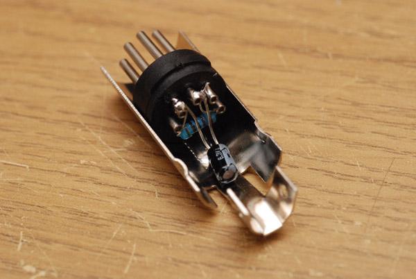
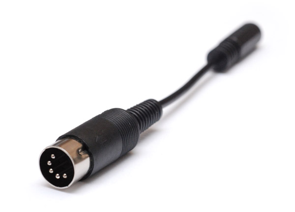
I started by getting some physically small, but high value capacitors (33uF, 6.3V). A bunch of 5-pin DIN connectors were very cheap, something like £2 for 10. They split open so you can wire them up - I started to wire up my little capacitor and resistor.
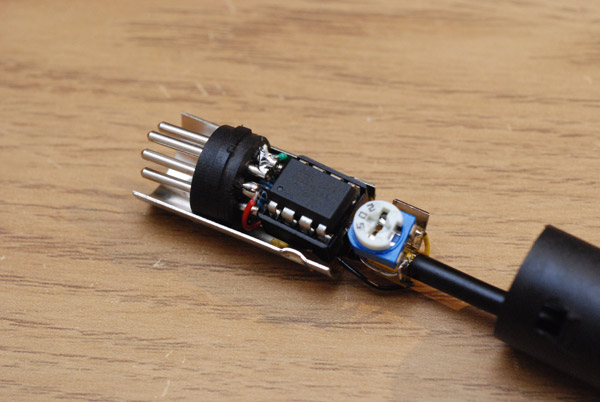
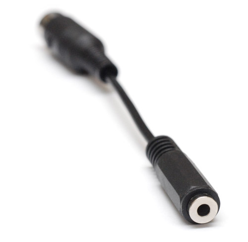
Then we add some wires (30AWG, of course), along with a 3.5mm audio jack. I actually stole that from a headphone cable splitter, the reason being, I wanted it to be moulded. It was also the thickest headphone cable I could find. I am the type of person that worries about a cable being too thin, given the bulk of a midi cable that the strain relief of that plastic cover was expecting... err, anyway. I folded only one half of the wire crimp down (but as hard as I could, to be sure) to make room to fit the potentiometer as far back as possible. This places it outside the metal cover, and the possibility of a hole in the plastic cover would allow one to change the volume externally. Oh, and last of all, the ATtiny85. There was even room to fit a DIP socket in there!
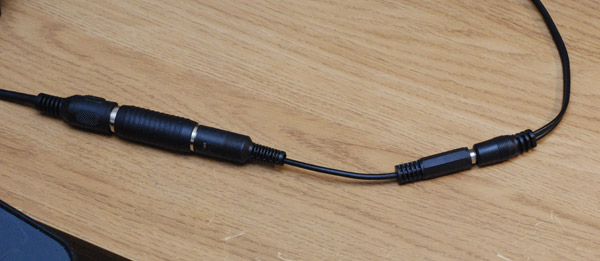
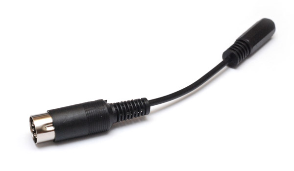
The cover goes back on, and, what d'you know, the whole synth is contained in that little plastic cylinder. In fact, when I tested it on my desk, the entire synth was smaller than the female-to-female midi adapter next to it. Here, midi comes in on the left, audio goes out on the right.
No batteries, nothing else needed, just plug and play.
What a marvellous chiptune machine!
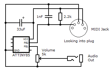
Naturally I developed the synth on my desk using that MIDI extension cable, but when I plugged it immediately into a keyboard it was occasionally having data errors. Which was odd, given that shortening the length of cable would normally improve the signal. It measured about 3Ω, which couldn't be doing much. I first thought that maybe the voltage drop was affecting the internal oscillator speed, but that'd affect the note pitches too. Finally I realized there was some high frequency noise from the keyboard, and the long length of cable was quite capacitive and filtering this nicely. I added a 1nF capacitor across the data line in the MIDI jack, and it now works flawlessly. Here's the updated schematic:
The relevant part of the MIDI spec is
Conclusions - for now
The best bit about this is that unlike any other MIDI synth I've ever known, there is no buffer and absolutely no lag. It is uncanny. The first time I played with it, I hadn't realized that my keyboard transmits noteOn values before the key actually hits the bed, and the synth responded so quickly that the notes were turning on before the keys were fully depressed. I felt as if it were reading my mind. What a brilliant feeling.You'll notice that the term 'synthesizer' is applied in the loosest sense: there's no filter, no envelope and just the one oscillator. One harsh, square oscillator. But for chiptune sounds, it can't be beat. The square waves produced are completely free of aliasing, since they aren't sampled (to be pedantic, they're effectively sampled at the clock frequency of 8Mhz). In this sense it sounds better than most digital synths when it comes to a pure square wave.
I had thought of continuing this with analogue output, that is, some PWM from the ATtiny85's 64Mhz PLL. While this is a well known technique for audio output, it won't really work on this physical cable, or at least, not in conjunction with the earlier mode. Their volume levels would be drastically different. Perhaps the next version shall use this method exclusively, but on the other hand, that'd loose the crispness of the square waves, since we'd be going back to a relatively low samplerate (~30kHz at best, depending on processor load). I've done a few tests with this, and I'm not sure if I like it. It does, however, offer the possibility of full polyphony. That, my friends, shall have to wait for the next episode.
There are a few things left to do on this invention before I feel it's ready for release - first of all, the modulation could do with improvement, regarding the phase issues. I'd like to get it to the point that it'll sound correct when used with aftertouch. I'm sure it can be worked out. Another issue is an audio glitch that I discovered: if you arpeggiate very fast across the boundary of an octave, it's noticeably clickier than normal, due to the prescaler changing. I haven't looked at the code in a while, but I am sure, with some thought, that this can be corrected. It would be nice to get the hardware double-buffering intended for PWM output to work in our favour.
Sustain pedal is something else that I forgot to add so far. This would need an additional note stack. You can't just ignore noteoffs as the pedal is held and turn all notes off when it's released. It needs two separate note stacks (notes held by the keys, notes held by the pedal) or it wouldn't know what to do when you're holding keys down as you release the pedal.
Yet another thing I want to do is try it on lots of different keyboards - it's only been used on three so far. I don't know if any of them output higher voltages, if so we'd have to add a low-dropout regulator. The standard just specifies 5mA.
Throughout this writeup, especially the latter half, I got lazy and forgot to include all the code examples. At some point I will put the full source code up. In the mean time if you want a look at it, just drop me a message. I've had a number of requests to buy this cable, so I may make a few of them.
The ATtiny85 - what a chip! Is there anything it can't do?