
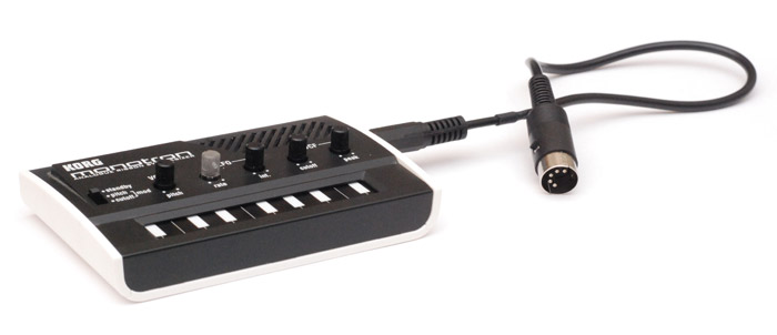
Midi Monotron
16 Aug 2015Progress: Complete
Analogue synths use analogue control voltages (CV) to control things. Such as voltage-controlled-oscillators, voltage-controlled-filters, and voltage-controlled-amplifiers.
I claimed not long ago that it'd be trivial to make a midi-to-CV adapter using an ATtiny85, but that since I didn't own an analogue synth there was no point. But then I remembered that I do have an analogue synth - the Korg Monotron! What's more, this thing was built with hacking in mind. There's no CV inputs or outputs, but they have added nice little labelled test points on the circuit board for you.
In addition, and to my delight, the entire schematic of the synth is available from Korg. Superb! This should be a walk in the park.
For a change, I decided to make something that was MIDI-compliant. That means optoisolation and no stealing-power-from-the-midi-signal malarkey. Powering the whole monotron over midi would work quite well, but I think I'll keep it battery powered. The battery voltage is boosted to 5V onboard, and we'll power the ATtiny from that.
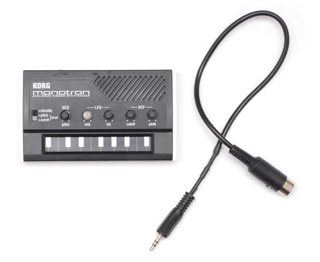
There's no chance of fitting a full-sized MIDI socket to the case. I considered only modding the monotron to have external CV inputs, and then building the midi-to-cv converter into a cable/midi jack. But we'd need at least a pitch CV and a gate signal, plus ground, and also power to the chip in the midi jack. I also wanted to control the LFO reset too. Since the only connectors I had were stereo 3.5mm audio jacks, and it would be stupid to use multiple jacks, I had to take a different route. The midi data is just two wires, so we could have a completely passive midi-to-3.5mm cable and all the circuitry inside, but in the end I went with something inbetween: the optoisolator is in the midi jack, the rest is in the monotron. The three connections are power, ground, and the midi data coming out of the optoisolator.
I took the code for my ATtiny85 midi synth and stripped out most of the sound generation. The newer code is actually a lot simpler. To initialize the fast PWM we call this:
	ldi r16, (1<<PLLE|1<<PCKE)
	out PLLCSR,r16

	ldi r16, (1<<PWM1A|1<<COM1A1|1<<CS10)
	out TCCR1,r16
	ldi r16, (1<<PWM1B|1<<COM1B1)
	out GTCCR,r16

	ldi r16,255
	out OCR1C,r16
which enables the PLL and gives us two PWM channels. From then on, writing to OCR1A or OCR1B will give us a pseudo-analogue voltage on either pin.
After prodding around for a bit, I have to say that I really like working with CV signals. They're logarithmic, so adding a fixed offset gives you a fixed offset in pitch. Lots of points on the circuit function as summing amplifiers, where the input resistance gives a weighted sum of the voltages. This makes things very convenient for us.
I found that an input resistance of about 30K to the pitch test pad gave the standard 1V/octave. From the 5V supply this would of course give us a 5 octave range, which is actually fine, since there's a main pitch control on the front panel. But thinking about it, as we're working in 8 bit, so there's 256 steps to our PWM, 12 semitones per octave... so 0.9375 V/octave would be more convenient. Then we can just shift and directly output the midi notenumber to the PWM. No lookup tables needed this time! It's tempting to try 0.46875V/octave, that'd give us a ten octave range, but I just have a feeling that we're asking for noise that way.
To smooth the PWM, and we really do want it smooth, I used a two-pole lowpass filter. I believe you're allowed to do this passively so long as the second stage has a much higher impedance than the first. See the right hand side of the circuit diagram below. This is followed by around 26K of impedance before the pitch pad. It's better to have a large resistance and then a small trimmer rather than putting the whole thing through a 30K pot. It makes it much easier to get it in tune.
The gate voltage, which turns the sound on or off, is not a true gate on the monotron – its voltage affects the pitch. This is a little inconvenient, but not too bad. The most important thing, like with all of my mods, is to retain complete functionality of the original item. In this case, so long as we tri-state all pins when no notes are playing, everything's dandy. In my research I found a couple of guides for adding CV-input to the monotron, which, when I tried their method, ruined the original ribbon by throwing the scale way off. Tsch.
Well, with CV and gate done, we can start playing with a keyboard. The arpeggiator works too. Excellent!
What doesn't work is the pitchbend and modulation, because with only 4 steps between semitones the 8-bit PWM simply wouldn't be able to cope. But we don't give up that easily. Time to think clever. Time to think analogue.
It's going into a summing amplifier with a weighted input resistor. So, we use the second PWM channel as a 'bend' voltage and give it a much higher resistance before connecting to the pitch point. And by adjusting this resistance we can vary the pitchbend range. Brilliant! Even better is the fact that keeping pitchbend/modulation totally separate from notenumber voltage actually makes the code much simpler.
Sending the MSB of pitchbend straight to the PWM, I found 300K of resistance to give the standard range of +/- 2 semitones. Using only seven bits for pitchbend gives us headroom for the modulation. Fantastic, we now have essentially a second LFO, optionally controlled by aftertouch.
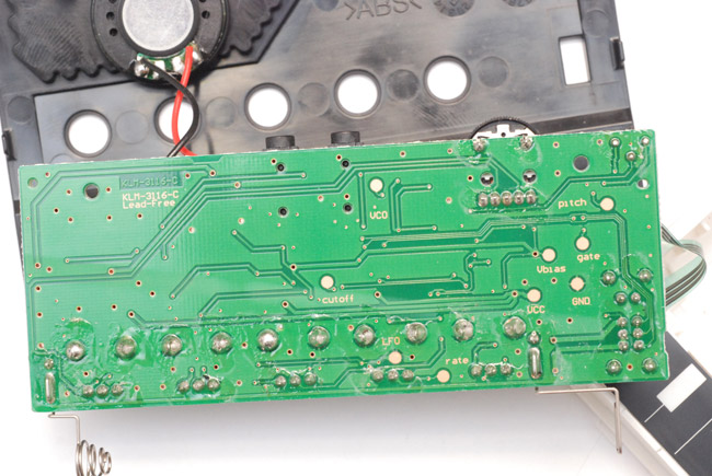
There's only one thing left to do, and that's the LFO resetting. The LFO on the monotron, in filter mode, acts as an envelope. It's important to retrigger it at the start of a note, which is done automatically on the rising edge of the gate voltage. But I'd like it to retrigger even when there's a string of notes without gaps between. And also to optionally retrigger when the arpeggiator changes note. The LFO reset signal does not have a test pad on the circuit board, and it took me some time to find it - three times I found something that reset the LFO, but also messed up something else. It's actually labelled on the schematic, but yes, the correct point to solder to is where I've stuck the yellow wire here:
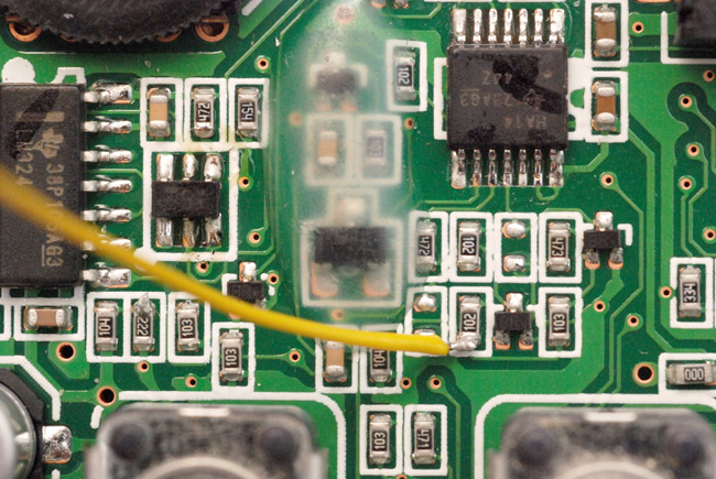
Just northwest of the LFO knob. A very short pulse high will reset it. I figured a physical switch to enable/disable this would be good, but all the switches in my drawer were quite big and would have looked ridiculous on the monotron, so I settled for a software on/off: CC65, chosen only because the yamaha KX5 has a button to send CC65 on/off signals.
That about sums it up. The final circuit:
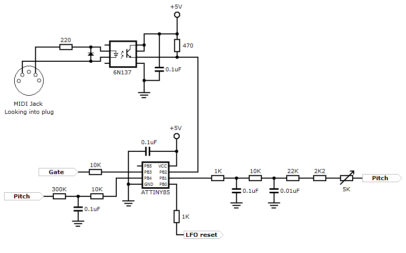
I hope that's clear. Just a single pole filter for the second PWM channel, on the left, but its cutoff is about 300Hz, as we know that pitchbend won't be changing at anywhere near that. I went to the trouble of the two-pole filter for the main pitch as the arpeggiator is capable of jumping up and down five octaves very quickly. Adding an adjustable lowpass filter to the pitch would have given a portamento control - I may do that later.
The internals, using a mixture of surface-mount and through-hole parts:
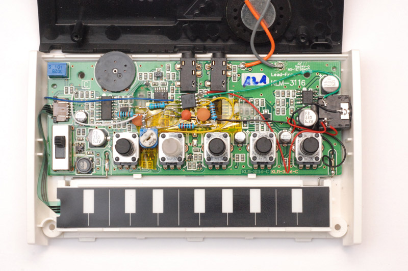
Blue is gate, yellow is LFO reset, white is pitch, green is midi data (oops, looks like it got trapped under one of the screws...). The stereo socket is just slotted into place, and a small piece of plastic is wedged between it and that nearby capacitor. This holds it nicely in a non-permanent way - no glue used. I stuck the trimpot there since it was as good as anywhere else, and at least it holds still as you adjust. I did try and think of a way of panel mounting it but came up empty. I could really do with a miniature version of an ordinary panel-mount pot.
Those SMD resistors are really satisfying actually. Very nice. For the midi jack optoisolator I used them exclusively.
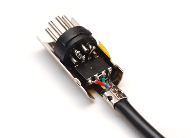
Plenty of room in there. Diode and capacitor are underneath the 6N137. I used a moulded stereo connector from one of the headphone splitter cables I tore apart to make those synth cables.
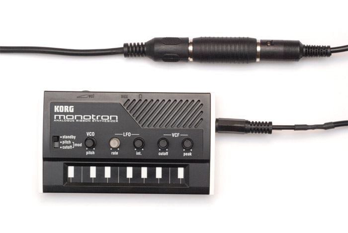
Full functionality retained. No one would suspect a thing.
Possible things to add: VCF control over midi, although I used up the second PWM channel on the pitchbend. A bigger chip would do it. I didn't think it was really needed as you have the control right there on the panel, but when using this with my keytar I do feel like full remote control would be nice.
The other thing I really ought to do, shouldn't take long, is put the chip into sleep mode when the cable isn't connected. It's not a switched socket, but a very mild pulldown, say 1M, on the data line would let us detect its presence.
We could, without much trouble, use the ADC of the chip to read the ribbon and give a MIDI out signal. That might be something worth doing if I found a bigger ribbon, actually. I've already used the monotron to control my reverse oscilloscope using pitch detection, and the main complaint is how small the range is.
Overall, an excellent use of a weekend. Much fun can now be had with an arpeggiating MIDI-controlled monotron.