Midi Interceptor
22 Oct 2015Progress: Complete
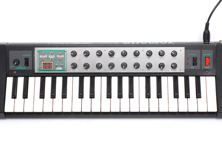
This project drew itself out for many weeks. I didn't end up with exactly what I set out to build – there were many compromises – but it certainly is functional, if not that beautiful. The idea was to add lots of midi controller knobs to my keytar in a way that didn't permanently 'damage' it.
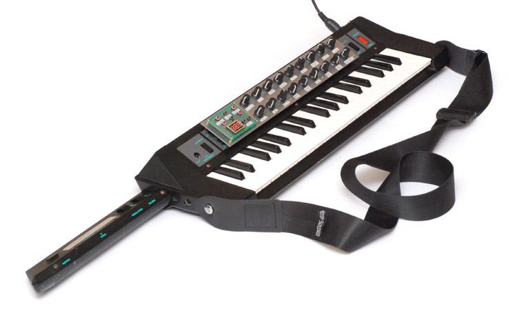
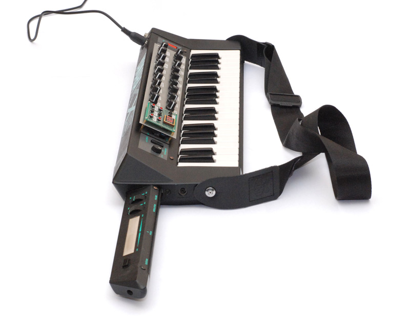
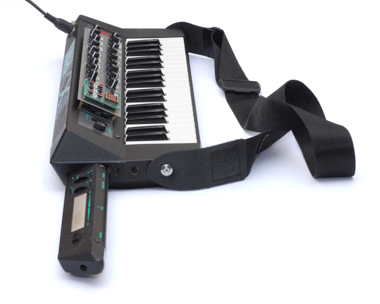
My final solution (for now at least) was to mount all the new controls on a separate panel that floats above the original.
I spent a very long time to get to this point and I'm still not totally satisfied with it, but it's sufficient. Many of the difficult decisions were about the choice of physical input relating to the messages it would send, and how that relates to the Reverse Oscilloscope, which is my synthesizer and the only thing I use the keytar for. Saying that, I didn't add a touch screen, which I had planned to, and everything it sends is generic midi messages.
Although it has a lot of knobs, it can't control everything on the Reverse Oscilloscope, and it has no way of inputting waves, but it does most of the job. The other things that it does are augmenting the keyboard's octave and transpose controls. The original was totally unsatisfactory in this regard. It would only transpose up or down one octave from the normal range, had no semitone transpose at all, and applying any change would wait for all keys to be released, presumably due to limited RAM. The bulk of the original controls were wasted on selecting a program: 12 buttons, in a group of 4 and 8, the combination of which would select one of 32 programs. Using the sustain button, you could get another 32! Very inefficient, all we need is 'next' and 'previous'.
I wanted to do this without gutting the original circuitry. Essentially the new circuit intercepts the midi data and adds in the new controller data. It also has to modify some of the data as it goes through to apply the transpose and so on. This means there must be, at the very least, one byte of lag (10 bits at 32kb/s =~0.3ms). An entire midi message takes about 1ms. I tried (and succeeded) to make the whole system have no more than exactly this amount of latency. Also, there's an override mode, accessed by turning it on while holding a button down, that completely bypasses the mod and returns to zero latency, if this ever became an issue.
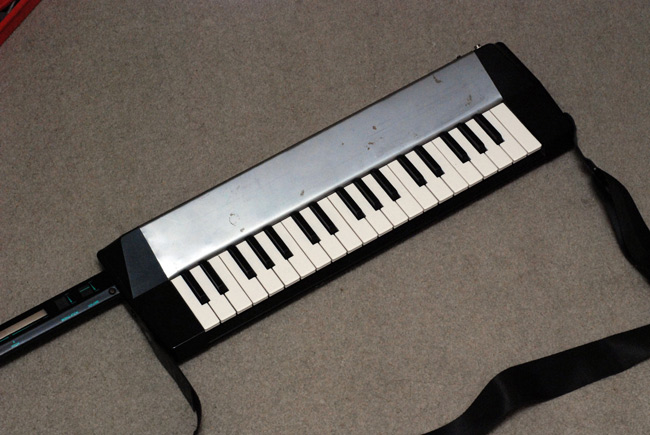
I didn't take too many pictures during construction. The first few weeks were spent trying to recreate the outer case of the keyboard, which is bent sheet metal, so that I could drill new holes into it for the new controls. I tried a few times, and in the end did have a suitable replacement case. With some paint, perhaps it would have looked good enough. But the bends still weren't as clean and crisp as the original case, and what's more, all of the controls would have stuck so far inside that one of the circuit boards would have to be modified or removed. That circuit board had no logic on it, but lots of soldered wires. Replacing it would have been tedious, and in all likelihood irreversible. Here's the only picture I have of the new case I made, before discarding it and starting over.
I really wanted to use momentary toggle switches for the up/down controls, but even the subminiature ones protruded behind the panel more than a centimetre. The ones I really wanted to use, paddle shaped, stuck in about 3cm. Even on a raised up panel I would have to modify the original case. I finally caved and went with simple pcb push switches.
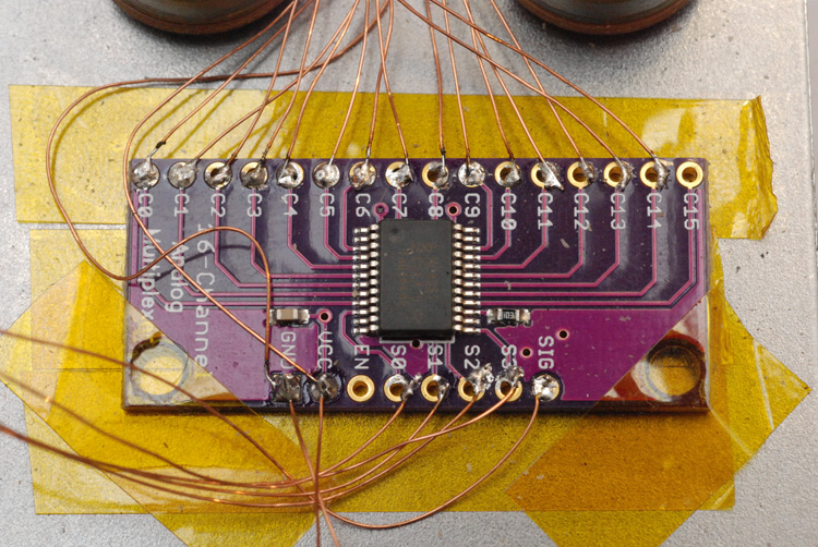
The main chip I used was an ATmega328p. There is a good reason for this: it's what the Arduino uses, and that means that it's astonishingly cheap, cheaper than other AVRs that are not nearly as powerful. As it happens the final code probably would have fit on a tiny2313 or similar, but it was nice to have room, and indeed, lots of IO pins. Funnily, the surface mount version has more pins (extra ADC channels) and although I've got some TQFP breakout boards, I'd been meaning to have a go at ELM ChaN's prototyping techniques for a while, and I had loads of enamel wire left over from that electric motor the other day, and, well why not?
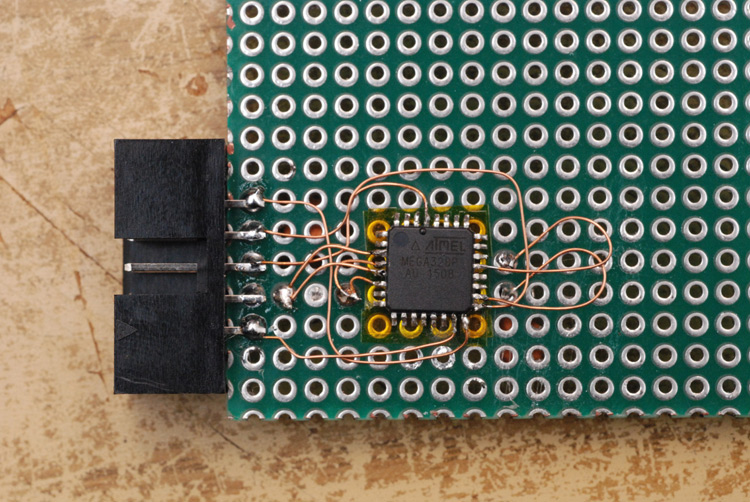
Putting the header connector end-on, and using kapton tape, I got the ISP working. It sticks out sideways so that the board can be reprogrammed even when the panel is fitted in place. Those long curved wires were a second attempt, the first ones being too short and so close to the chip that it was melting both ends at once. On the underneath of the board I'd fitted an inductor and capacitors for a heavily filtered analogue supply.
The main advice I can give if you want to copy this is, tin all of the legs of the chip before you start soldering to it!
The actual controls I decided to implement were: 15 potentiometers, 3 rotary encoders with buttons, and 6 (later 8) push buttons. I used a 16 channel analogue multiplexer for the pots, and ended up using an 8 channel analogue multiplexer for the keypad, driven by the same address lines, meaning the 8 buttons were added and only consume 1 pin.
There exist "mergers" for midi data, but I expect they would have more latency than the the method I finally implemented, since I can't fathom any way of reducing the latency further. The one exception would be if we only wanted to add CC data, and pass the keyboard's signal through unmodified, we could choose only to transmit the additional data in place of the Active Sense that the keyboard always reads out when idle. Then you would only need to delay the keyboard data in extreme cases. This could be done, only because the keyboard does not in any way make use of running status. An ordinary midi merger would have to account for this, if necessary adding extra status bytes, and definitely having to read bytes before transmitting them.
On condition that all data bytes, or data byte pairs, are preceded by status bytes we can implement a very simple circular buffer. I made it 256 bytes and just let the low address overflow. We use three pointers to this: read, write, and end. The transmission data-ready interrupt reads in whatever is at the read pointer, checks it is valid data and if so, transmits it and advances. (It disables itself if there's nothing to transmit, otherwise the interrupt will call continuously.) Receiving a status byte writes it at the write pointer, and advances the end pointer by two or three, depending on what the status was, to make room. Receiving a data byte writes it in that room. Receiving also re-enables the data-ready interrupt. Overall this gives a lag of at most one byte.
While that's running, all we have to do is advance the end pointer and write three bytes, and that message will get mixed into the output. Easy.
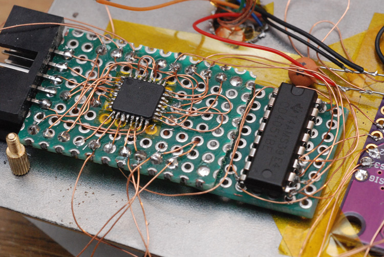
There's the 8-channel multiplexer, and I didn't realize how tall through-mount parts are and had to cut a bit of protoboard off and solder it a layer lower for height reasons.
Those connections along the bottom are all the rotary encoders. I changed my mind more than once about which pins to connect them to, finally opting for one each on ports B, C and D - so each one has its own separate PCINT interrupt.
Above, that big resistor is in-between this board and the power cable to the display. I forgot to mention it - simple 3 digit affair, just to output a number 0 to 127 (or down to -36 for transpose). The reason for the resistor is that the display uses a MAX7219 (the last one in my box, so soon!) and I had no idea how noisy those things are. The fuzz it threw off played havoc with my analogue readings, and only through multiple low passes could I quieten it.
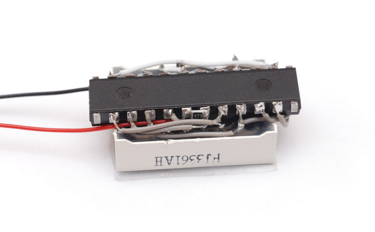
A compact display. Just a fixed SMD resistor to set the brightness.
I had no idea how hard it was to turn analogue readings into midi data. I really thought it would be straight forward, but... wow. When I started this project, I was impressed at how the built-in controls on the keyboard seemed to work astonishingly well. You would set a value, and it would stay at the value. No wobbling or repeatedly sending the same number.
I am proud to say that by the end, my controls behave much better than the originals. In fact it makes the originals look poor – they do, on occasion, send sporadic values, and what's worse the thresholds for changing them are so large that it's hard to get a specific value, often it jumps in twos or threes. Sometimes pushing a knob to an extreme fails to get the 0 or 127.
My (eventually) working strategy basically amounts to very heavy filtering on the analogue circuit, keeping it totally separate from the digital, and being explicit about the change detection. Measure at above the needed resolution, take the absolute difference between this reading and the previous reading, and only transmit if it's above a threshold. Simply rounding into bins is doomed to fail. The final result is very satisfying. Set it to a value, it stays rock solid, move it a tiny bit further and the value goes up by one, and it never transmits the same value twice in a row.
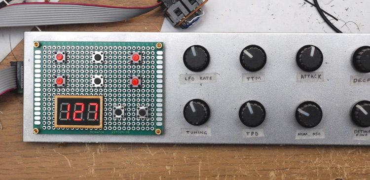
A little laser-cut border for the display. My embossing label maker's font was much too large, and my temporary labels, made from masking tape, ended up being far more permanent. I was planning on lasercutting a stencil of some kind, but honestly the amount of effort it takes to remove all those knobs and reassemble them after is colossal. Maybe later.
The top buttons are for transpose, octave and program. Program is easy to send of course. In order to transpose though we need to worry about what happens when you transpose while holding down keys. The naive approach might end up sending a different notenumber for the noteoff messages. The original keyboard's way of dealing with this was just to wait for all keys to lift up, which I found annoying. I preferred to have a lookup table for each key (it's only 37 bytes of course) and when a noteOn message comes in, store for that key the transposed notenumber that was sent. Then you know exactly what the noteoff needs to be changed to.
There is one flaw with this method, which is if you transpose over a note being held it's possible to send two noteOn messages with the same number. It would take quite a bit of effort to mute the keys that would be capable of this, and most synths should handle this gracefully, so I did nothing about it. Having said that, my synth cable would tangle its arpeggiator if that were to happen. I don't imagine it's a situation that would ever come up while playing anyway.
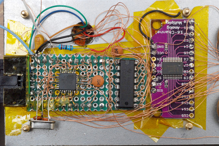
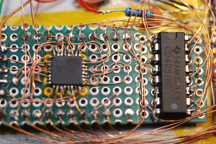
Not done yet but that's the last picture I took before finishing and bolting it together. I realized at a relatively late stage that it'd probably be a good idea to have a crystal, what with the UART timing and everything. It certainly looks like an afterthought. Another thing I didn't think about at the start was how to hold that main board in place, tape is not sufficient, not if we want to use that ISP connector from the front. I ended up (not shown in the picture above) soldering some heavy gauge copper to the few unused pads, and then soldering these to the brass standoff bolts. Possibly a little more permanent than I wanted but it certainly holds it steady.
I read that the Aref pin should have a capacitor on it to ground, so what the heck, I added it. Brings the total number of 100nF capacitors in this project to about 20. Most of those were on the analogue section, along with tantalums and electrolytics. Some were on the legs of the rotary encoders, to provide some quality low-pass filtering in order to debounce.
The encoders output a 2-bit Gray code. I knew that but didn't expect them to output the entire sequence of 4 states each click of the rotation. It makes sense though, as it means you can measure direction and velocity from one click. I cheated a little at reading them, just wait for a pin change, and whichever pin has gone high gives you the direction, then disable the pin change interrupt until both have gone low again. Works fine but feels a little odd, almost as if it reacts too fast, and is out of sync with the click.
Although I flooded the board with ceramic caps, there is a risk of too many caps, especially when it comes to the higher values. Too much filtering means slower rising power, and the turn-on sequence caused me great distress. I initially blamed it on power rising times, and tried to optimize the amount of capacitance, but actually it turned out to be completely unrelated. The symptom was that the pointers to the circular buffer seemed to go out of sync and miss every 82nd message, but only from initial powerup, resetting the micro made everything dandy.
The keyboard, as it's powered up, transmits zeros for all readings, and then actually reads out the ones that are non-zero. I wasn't getting this on my USB-midi adapter, but when I finally thought of it and checked the actual data with an FTDI board, it turns out that this fixed message of all zeros is preprogrammed and makes use of running status. No other part of the keyboard uses running status, just this standard message it sends at powerup. Knowing that, my fix was just to explicitly ignore extra data bytes, but it took me a very long time to work this out.
The main circuit board of the keyboard had a header connector with a shielded cable leading to the actual midi socket. This made it very easy to intercept; just unplug and replug. I used shielded cable as well, but the only shielded cable I could find was high voltage stuff and it was very stiff. Probably overkill but it's nice to be on the safe side. I implemented the transmitter circuit exactly as the midi spec asks for, for 5V. The circuit may not be running at 5V though, more likely at 5V minus the drop of the linear regulator (I usually power the keyboard from USB, but it's designed for 9V). The midi people did update their tech specs for lower voltages, just change some resistance values, but I don't think it's needed. I tried sending midi data to a bunch of stuff, and it even drove my midi synths that relied on their internal pullup resistors, which the original keyboard was unable to transmit to.
The lower two buttons on the keypad are +/- for assignments. Every controller is customizable, and if I want it to transmit for a different controller it's only a button press away. In addition, the original knobs and buttons of the keyboard are now assignable too – it's pretty much identical to implementing the transpose for note numbers. This is indeed quite satisfying. I didn't yet make the aftertouch assignable, that'd take a little more effort since the channel aftertouch message is only two bytes.
Currently the assignments are loaded from program memory when it starts up, and changed only in ram. I wondered about storing changes to the internal EEPROM (non-volatile memory) but didn't get round to it. I can imagine it becoming confusing. My M-Audio keyboard always infuriates me, since you can assign various knobs but one accidental press of a button like 'zone/group' changes all of them to a different arrangement. And turning it off and on again makes no difference since it's all non-volatile... to be fair I haven't read the manual, but let's keep things simple for now.
I did add the feature of pressing both assign buttons together resets to start-up configuration. I probably spent way too long getting the 'feel' of this right. As you reset, the display shows three hyphens, and then waits for both button releases, turning back to three zeros. This looks like it's blinking as you do it. In fact the feel of the buttons was wholly overengineered, but perhaps I was just sour about not getting to use my momentary toggle switches. Pressing a button triggers a change, holding it for X milliseconds retriggers it every Y milliseconds. A bit like the delayed-auto-shift in tetris. But getting something like that wrong can change the whole feel of the project.
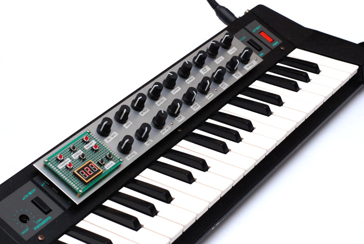
When it came to final assembly, I considered using magnets to mount it in a non-permanent way, but found them to slide around a lot. And so I bolted it on using M2 standoffs, which meant drilling ten 2mm diameter holes in the case. These are about as subtle as you could ever hope for, and you could probably get away without patching them up if the panel was removed. To position them, I laid them out on the panel and fitted the standoff bolts, then aligned it and drilled the corners, and with them slotted into place I put masking tape on the keyboard and sharpie ink on the bolts and pressed them together to transfer the positions. Worked well enough.
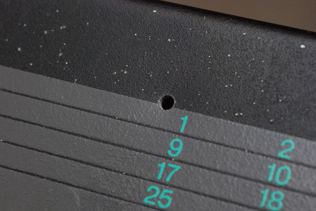
Ten tiny little holes. I think the reason I want to keep the mod reversible is not for resale value, but to keep open the door for further, future, better modifications.
I must have been getting tired because towards the end I made a silly mistake. The case bolts onto a bar along the top of the keys. The bolts holding the new panel, and the nuts fixing them, now intrude into that space, so holes have to be drilled in it to accommodate. I didn't worry much because this wouldn't be visible, but on the first hole I slipped and gouged some deep scratches into two of the keys. Infuriating, even if it is almost invisible. For drilling the other holes, I put a guard over the keys as I should have done in the first place.
So there we go. An augmented keytar.
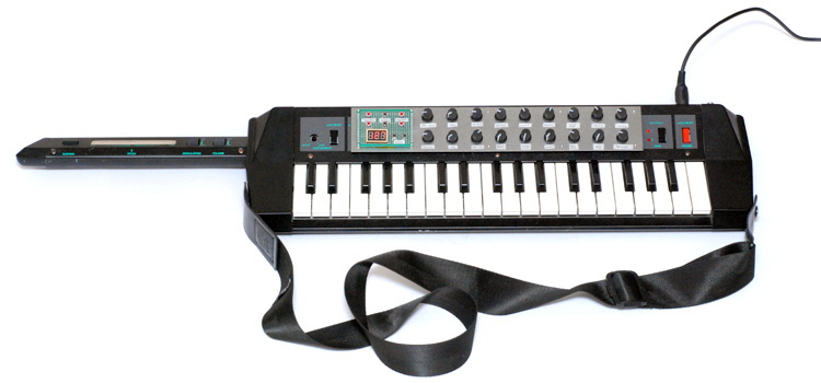
It has a look. I can't quite name its look, but it certainly has one.
I would not say that it is finished, only that this round is over.