
Microscope Light
13 Mar 2026Progress: Complete
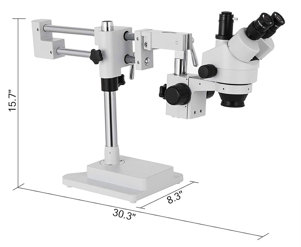
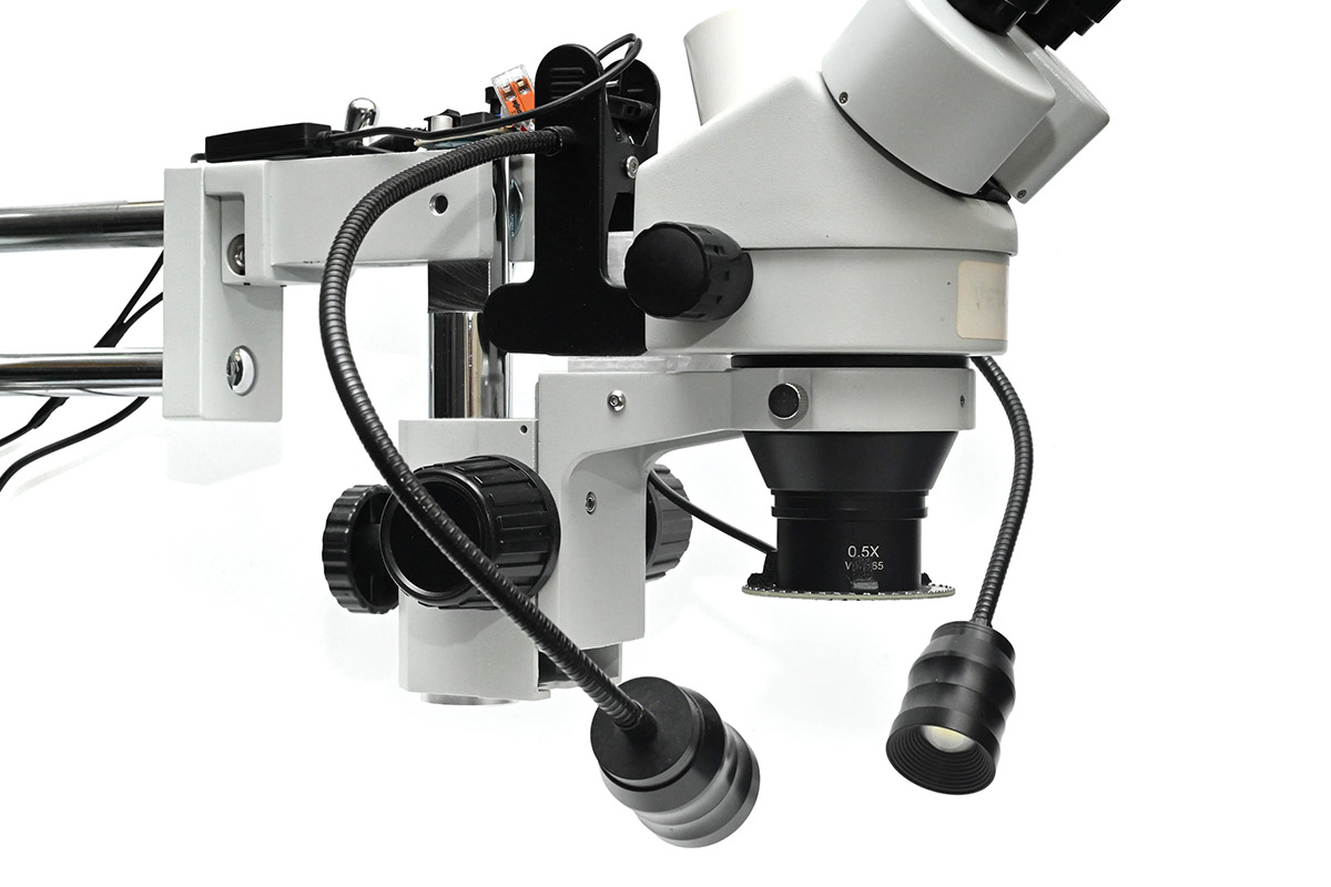
Last year I invested in a new microscope, a trinocular type, to hopefully film some videos directly through the scope.
The biggest bit of advice I can give, which I only found out by trying one in person, is that there are two types of trinocular microscope. The cheaper type has a switch, that blocks out the left eyepiece and redirects the light to the camera port. The other type, that can film while both eyepieces still work, is marketed as "simul-focal".
Given that I am heavily left-eye dominant (and have some vision problems with my right eye), a trinocular scope without the simul-focal feature would have been useless to me. I dodged a bullet there.
The cheapest simul-focal scope from AmScope was just over a grand, but I bought a clone of it for about a third of that.
Conclusions:
- It's a reasonably good bit of equipment for the price
- Even with the Barlow lens fitted, the distance to the focal plane, and the depth of field, are smaller than with my old (fixed magnification) microscope
- The camera port is usable, but somewhat underwhelming, more on that below
- It didn't come with any lighting, and all of the options are awful
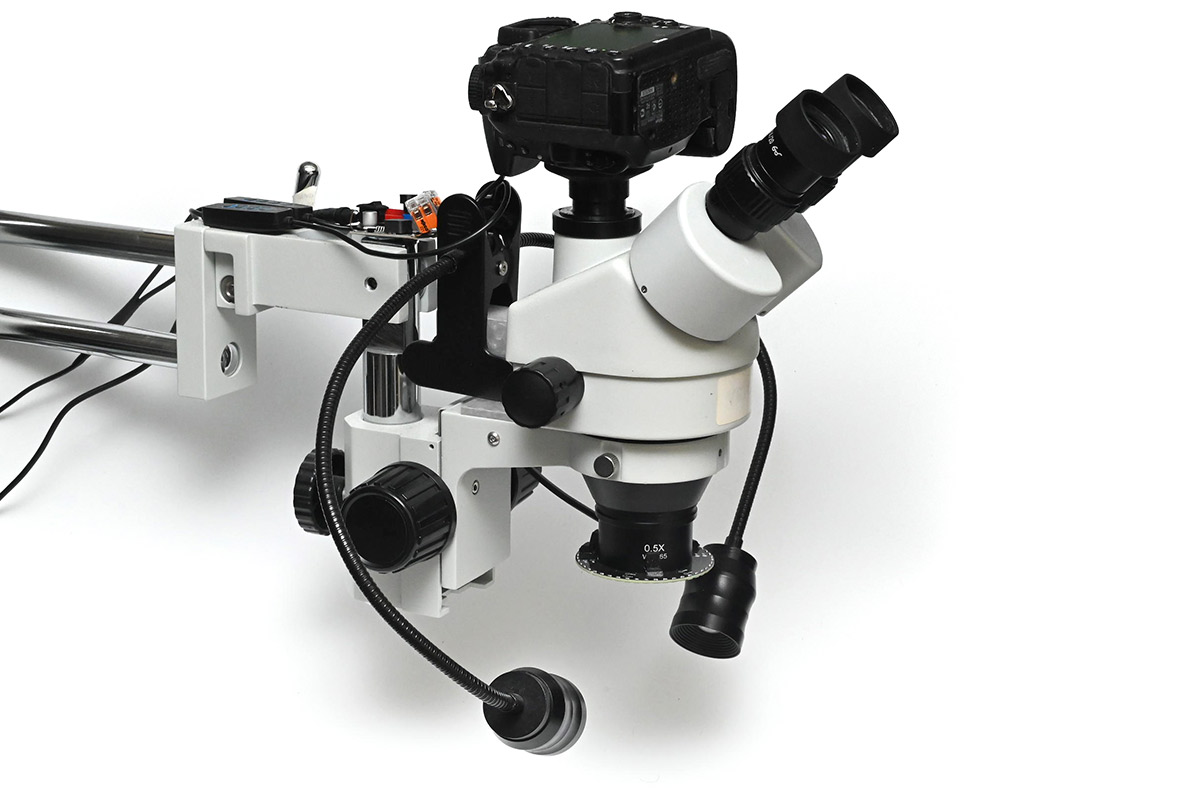
Camera mount
Despite being "simul-focal" there are still only two objectives, so presumably there's a beamsplitter inside taking the view from one eye. That's possibly the reason I struggled to set the camera up. I wonder if the ready-made camera adapters have further optics in them.I found that I could hover my DSLR about an inch over the port and get a usable image, so I set out to 3D print an adapter to hold it there. I took somebody else's Nikon lens mount model from Thingiverse and added an adjustable tube.
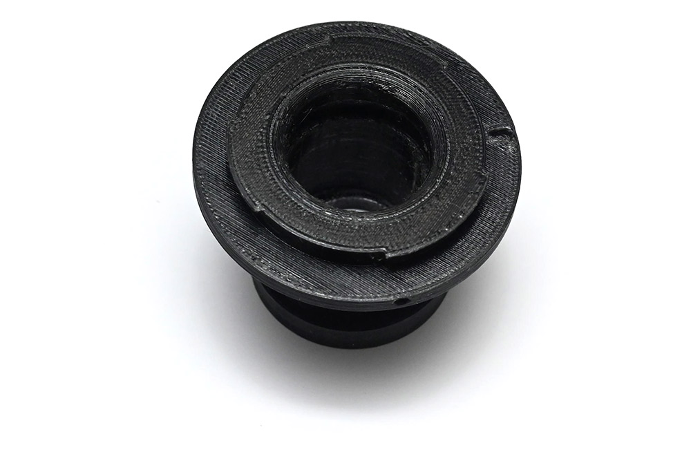
After about four attempts I got something passable. The problem is that the light is taken from one objective and as such the focal plane is angled. I found that a crop-sensor DSLR, with a further 1.5 crop, got a similar field of view to the viewfinders, but the left and right edges of the frame were out of focus.
I managed to mostly correct the problem by holding the camera at an angle, about five degrees to the horizontal.
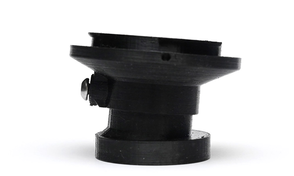
This could be improved but I was getting tired of wasting filament, I'll possibly try again later. There is enough play in the two parts that it can be wiggled into the right place and stays put unless it gets knocked.
Lighting options
Having good lighting is far more important than having good optics.My previous microscope came with a single power-LED on a gooseneck. It worked quite well. This new scope came with nothing.
A lot of the expensive microscopes come with a fibre optic ring light. They have, presumably a big halogen bulb in a box and then a cable leading to the mounted ring.
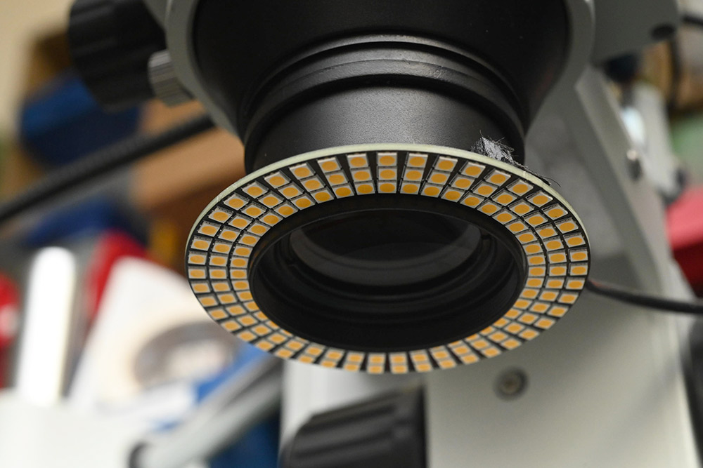
A cheaper option is the LED ring light. Lots of people recommended this 144-LED ring light, so I bought one.
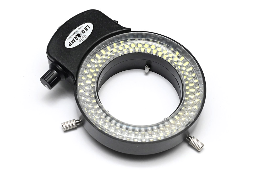
It's useless and I hate it. First, the light quality is awful, a cold white, nearly blue, with very poor colour rendering. No good for filming. Second, there's no diffusion, and the LED positioning gives a weird lack of depth to the visuals. Sometimes shadows can be helpful to see what's what. Finally, the whole thing is huge and gets in the way of using the microscope. I found myself knocking it repeatedly as I tried to adjust things and the attachment is so poor that it often fell off.
I chucked it in the bin!
One final insult is that I kept the power supply, 12V with a 5.5/2.1mm barrel jack. This turned out to be reverse polarity (centre negative) and it would later go on to damage some other equipment.
Custom ring light
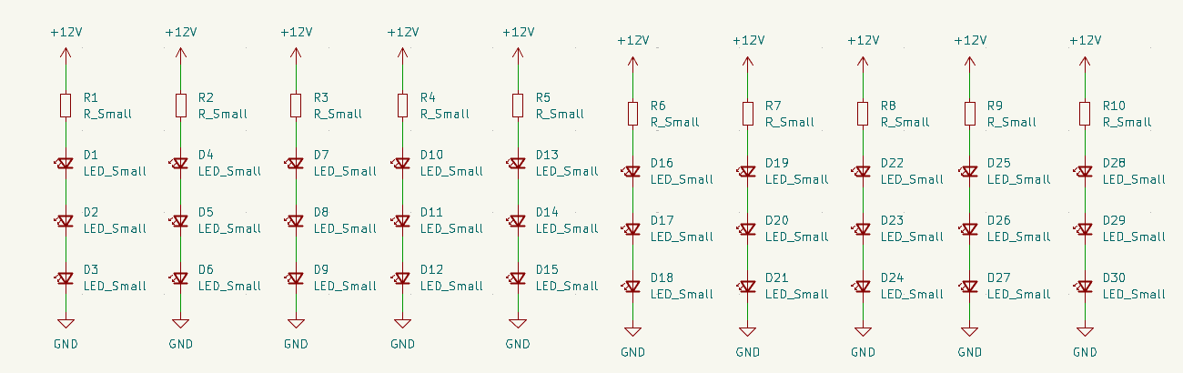
There are plenty of other ring lights available but instead of wasting time and money trying them, given how cheap PCBs are to create, and the fact that I have a reel of high-quality white LEDs left over from an old job already mounted in the pick-and-place machine, I figured I'd make something custom-fit. Ideally, as bright as possible, but as physically small as possible too.Following the example of 12V LED strips, I crammed the LEDs into series groups of three with a single limiting resistor.
To arrange the PCB, I used the circular array tool (Ctrl+T). It's not the first time we've wished for non-destructive modifiers in KiCad. To change the layout, I have to undo or delete back to the base unit, make my changes and then apply the circular array again.
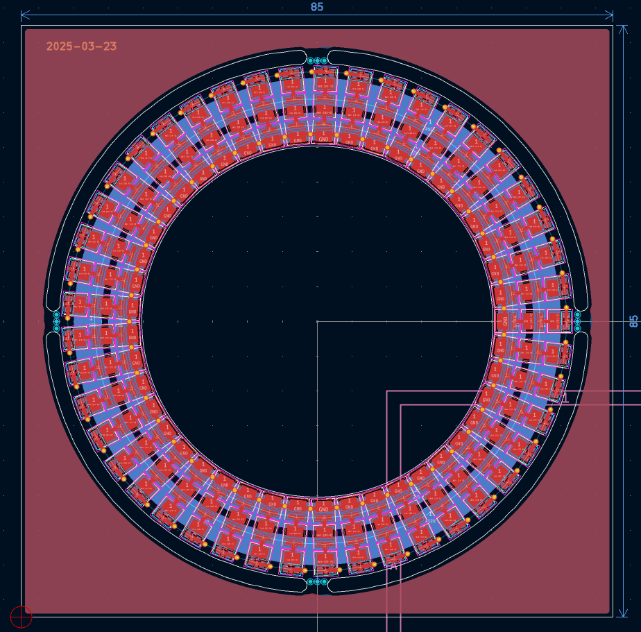
The inner diameter is 50.4mm, just a smidge bigger than the barlow lens, and the outer diameter is 74mm. I don't think I could pack the 135 LEDs any denser. In contrast, the off-the-shelf light was about 100mm by 140mm, not including the protruding clamps or the cable that leaves in the least convenient direction.
The LEDs are a 3030 footprint and rated for 65mA continuous at 2.81V, so if we run this from a 12V 2A supply we can give each triplet about 45mA. In the end I decided to assemble with a limiting resistor of 150Ω, which would be about 24mA per triplet, just to keep things fairly cool, with the option of boosting the brightness if we need to.
For the board outline, turning simple circles into those arcs that intersect perfectly is a task notoriously difficult in KiCad. I suppose a polite way to put it would be "out of scope". Instead, I drew up the panel in FreeCAD, exported as DXF and imported to KiCad.
To mount this I modelled some spring clips, again in FreeCAD.
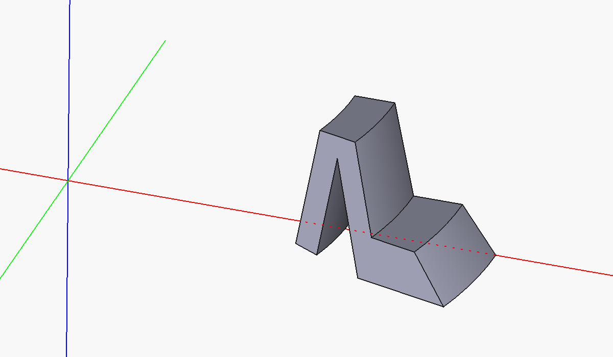
Slight curvature matches the 50mm diameter of the Barlow lens. These were superglued in place. Because of where the resistors are, they took some fettling to get it to fit. Couldn't be bothered to reprint.
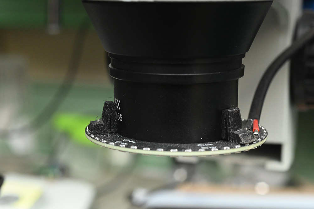
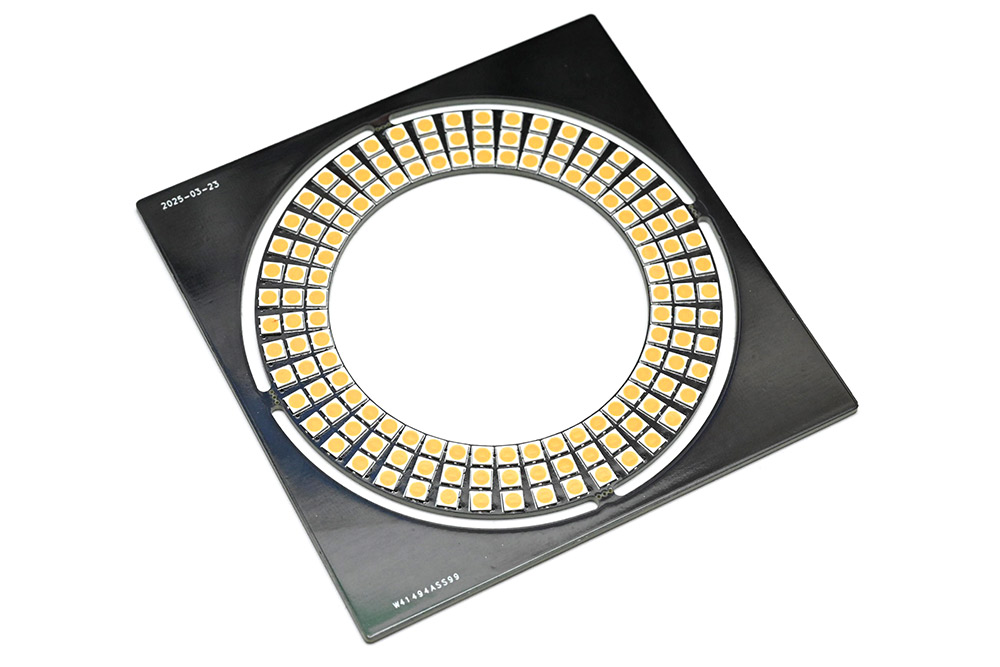
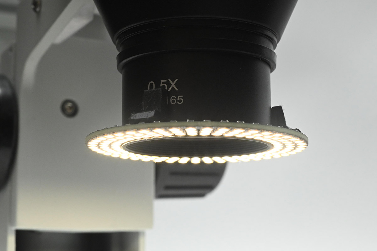
Driving this with 12V, the results are spectacular, and physically it's as small as can be.
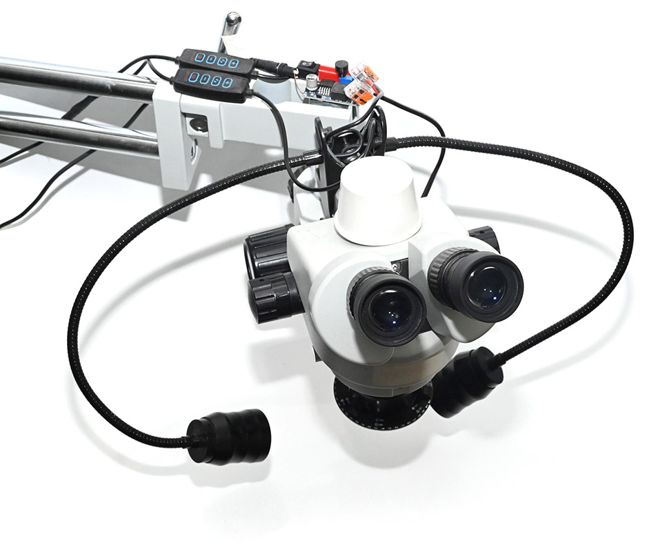
Goosenecks and brightness control
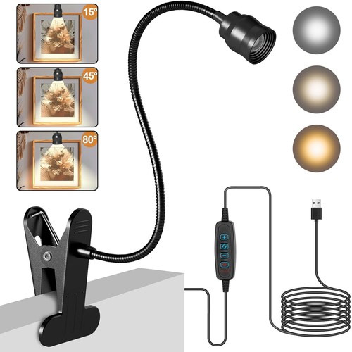
The diffuse light is great, but sometimes we want a more direct, sideways illumination to add contrast. I really missed the gooseneck LED of the previous scope, which could be positioned perfectly.To augment my lighting, I ordered a couple of gooseneck USB lights.
I dismantled and reassembled them to make use of a single clamp, then 3D-printed a cuboid for them to clamp to. Again this was done in FreeCAD, and hastily – the dimensions were off by a fair bit, but corrected quickly with a hacksaw.
Controls for each gooseneck were stuck to the boom. They have adjustable colour temperature (in reality, it's one warm, one cold LED, with a choice of one or the other or both). Also attached was a basic brightness control for the ring light.
The trick to the brightness control is to use a buck module (not buck-boost) which is fed from 12V. The module can lower but not increase the voltage, so it's inherently safe to just add a knob (again 3D printed) to the trimpot on it. This works very well despite being the laziest solution possible.
The unusual shadows are from the white panel I wedged behind it, in an attempt to conceal the disgusting state of my workbench.
Colour temperature
Using this for a few months, I soon began to crave a more neutral colour temperature. The original idea had been to use up those LEDs left over from an old job, but they were very warm white. Irritated, on my next digikey order I chucked a bunch more into the basket, at each of the available temperatures. We still had four boards left to populate.
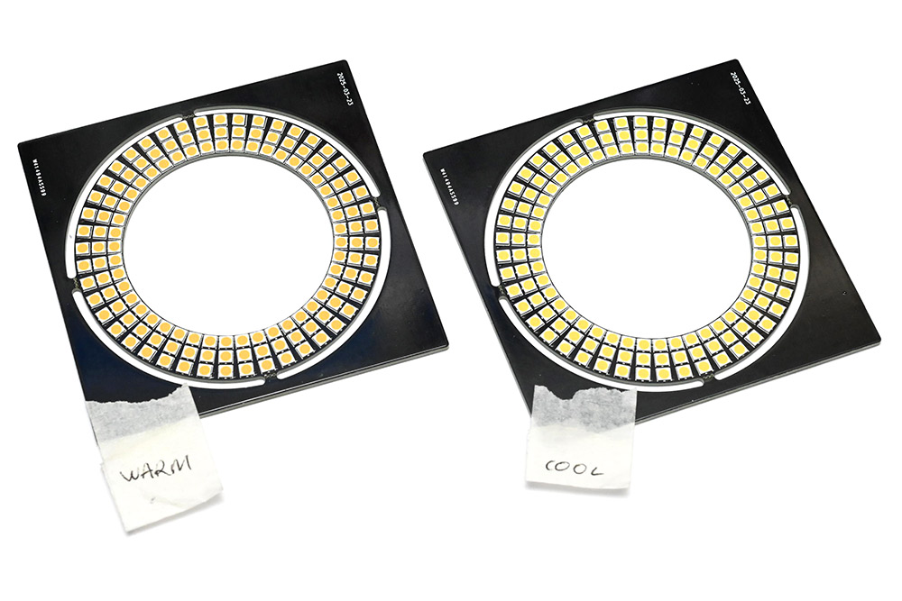
The neutral white, at 4000K, seemed the most pleasing (Part number JB3030AWT-P-U40EA0000-N0000001, CRI 90, about £7 for 150, but there are much cheaper options available). I swapped out the microscope light for that.
Here it is with the DSLR mounted:
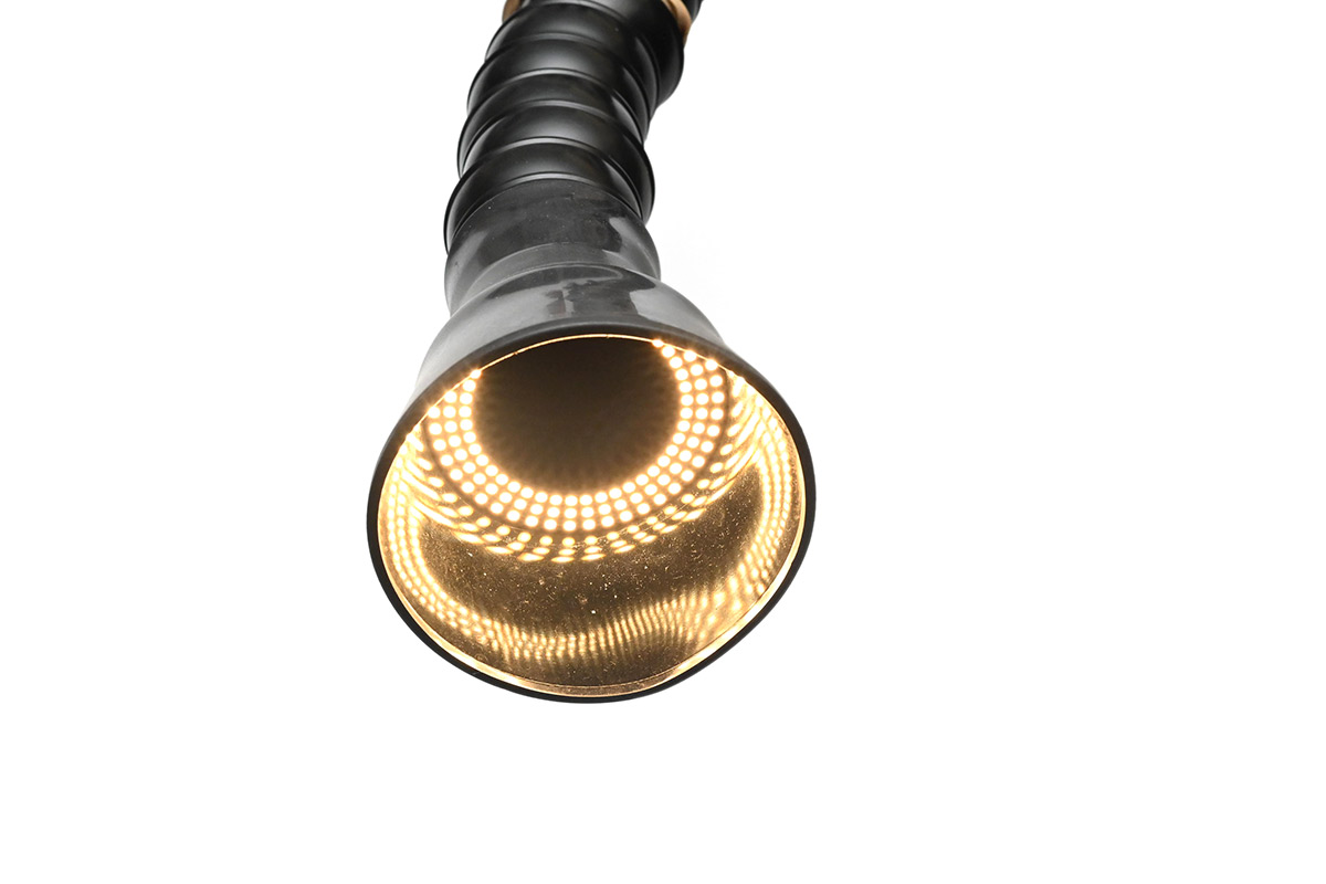
Fume extractor
Another investment in recent months was an industrial fume extractor. It cost about £200, is the size and shape of a vacuum cleaner, and has a semi-rigid positionable hose you can point at the action. I regret not buying one sooner, it makes the process of soldering substantially more comfortable and means I no longer have to hold my breath.About the only downside is that if you cuddle it right up to the work then it blocks out some of your light. To my delight, this ring light I'd designed for the microscope, of which I now had spares, can be wedged in perfectly into the end of the hose. A small slit in the rubber funnel lets the power cable escape.
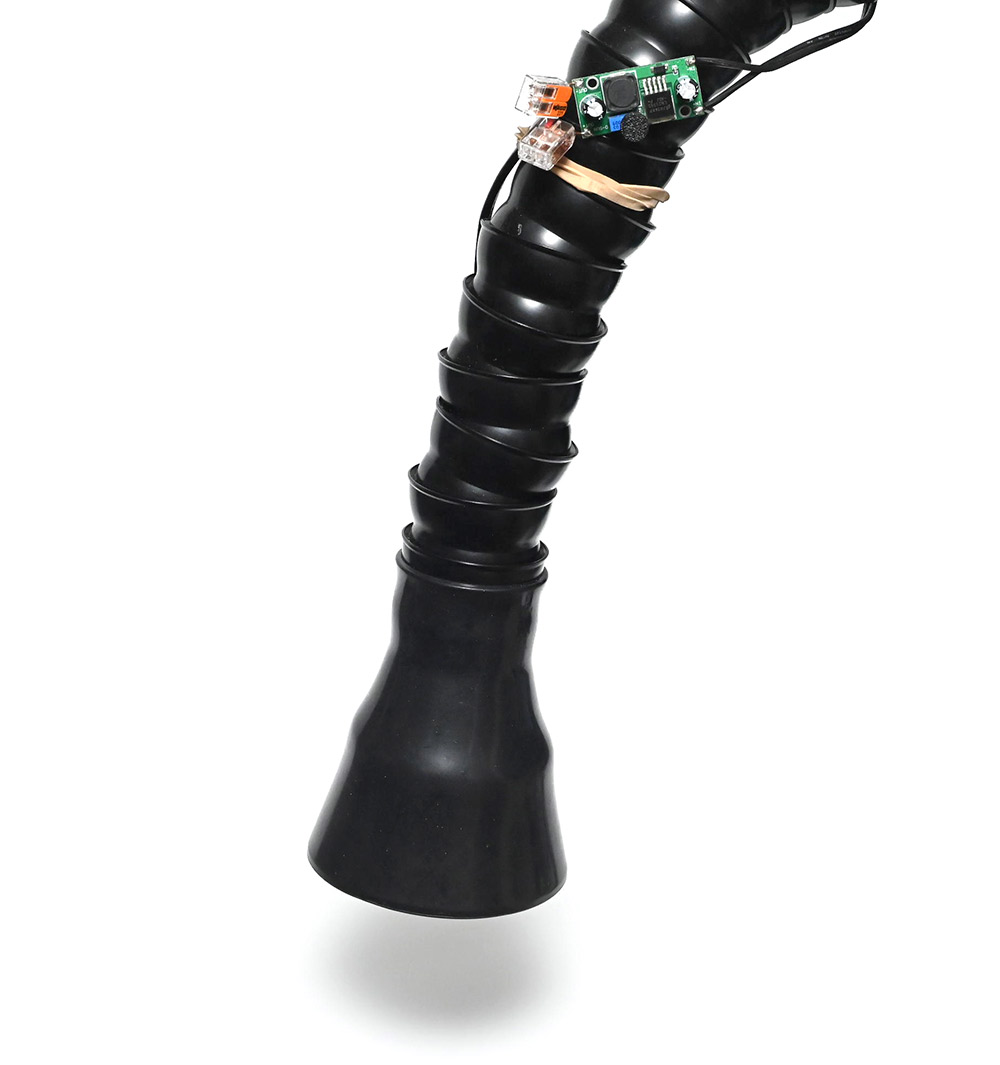
The same type of step-down module, with 3D-printed knob, allows brightness adjustment and is attached with an elastic band. I have a switched power strip to the side, that lets me toggle the extraction and lighting on and off.
It draws about 10W at nominal full brightness. It could comfortably go a lot brighter as the airflow gives it extra cooling but this is already more than I need.
To conclude, these small improvements to my soldering setup – micro improvements, if you will – have made a big difference. Not sure if they warranted their own project page, but there you go. Much easier than documenting some of my bigger projects of the last few years... I'll post them eventually.
The KiCad and FreeCAD files are available to download here.