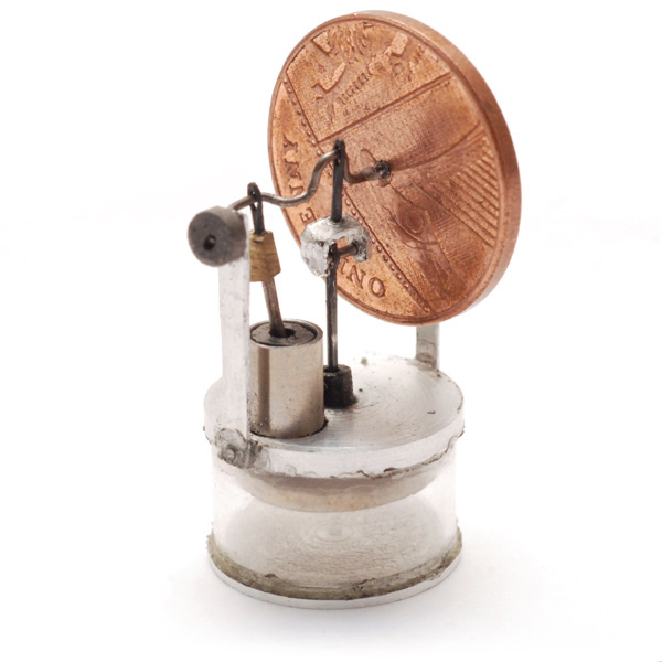
Micro Stirling Engine
8 Sep 2014Progress: Completeish
It's no secret I've been trying to build a stirling engine for some time. I was held back by my lack of tools, it's true, but now that I am a lathe owner there really is no excuse. But I have a strange condition leading to idiotic levels of overambition. So I put my "ordinary" sized model stirling engine on hold and tried something a little more challenging.
Stirling engines are notoriously difficult to get running when they're miniaturized. Despite their excellent efficiency given the conditions they work with, they tend to have an incredibly low power-to-weight ratio. The ratio can be improved by pressurising the working fluid and/or using helium instead. These options are pretty much out of the question for model builders.
Difficulty acknowledged and I still attempted to make the engine absolutely as small as possible.


Well, it doesn't run. I think I have diagnosed the main issues and when the mood strikes me I shall try again.
The dimensions, displacement ratio etc were plucked out of thin air and may be a factor in its failure to produce enough power to overcome friction.
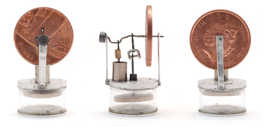
The glass around the displacer piston is from a 15mm test tube. It took some time for me to successfully chop test tubes with a clean break. I had no success with scoring and thermal shocking, so I ended up just placing it in the lathe, mounting a mini-drill to the toolpost, and slowly approaching with a diamond grinding wheel. I drip water on the cut to prevent overheating, and cover all sliding surfaces to stop the abrasive dust getting in.
The power piston bore is 4mm. The inside was lapped to a mirror finish. The crankshaft and conrods are pins and needles. I found great variation in the metals used for these - ordinary pins are unhardened; glass-headed pins are hardened but can be annealed easily; needles are hardened, they're some type of air-hardening alloy. The only way to soften them to be workable was to heat to an orange colour, and then very very slowly lift them away from the flame. Sometimes I was impatient and as soon as you go to drill, the thing shatters.
I wanted to use needles for two reasons. One, they have a very finely polished exterior which is perfect for a sliding bushing. Two, they have a convenient eye which serves nicely as a pilot hole for crossdrilling.
The rest is scrap aluminium. I had to pin the supports on using chopped up needles, which provides a mechanical attachment to reinforce the superglue. The glue is applied liberally all around the displacer cylinder as I really wanted it to be airtight. The displacer itself is balsa wood.
The brass linkage required drilling very small holes to accept the two needle heads. I found the best way to do this was to make my own drill bits. I did this by grinding a spade shape in the end of a hardened pin. There was no need for flutes as I was peck-drilling anyway.
The piston and bushing are graphite (or so I thought). I ordered some "carbon electrodes" which were incredibly difficult to machine. The material would crumble at the slightest shock, but dull drillbits very quickly. This probably should have alerted me to a problem sooner.
Having completed the engine, and finding it to be unsatisfactory, I actually decided to test this graphite against some other low-friction materials. A huge disappointment: I suppose I was doomed from the start and it's my own fault for not checking this before I started. I can't easily fix this as the thing is built with superglue, it'll be easier to start over. Some research later and it seems these electrodes are constructed by binding graphite powder together with an epoxy resin. Ah.
Another problem, a mistake I made at one point, was to hold the displacer rod in an ordinary pair of pliers. This was purely laziness, as I own a set of brass-jawed pliers, but assumed it would be hardened enough that I wouldn't need to worry. It was only in the post-mortem that I discovered toolmarks on the surface, and as I had tried to run-in the engine, this was abrading the graphite bushing and making it progressively more leaky. This will be easy to avoid repeating in mark II.
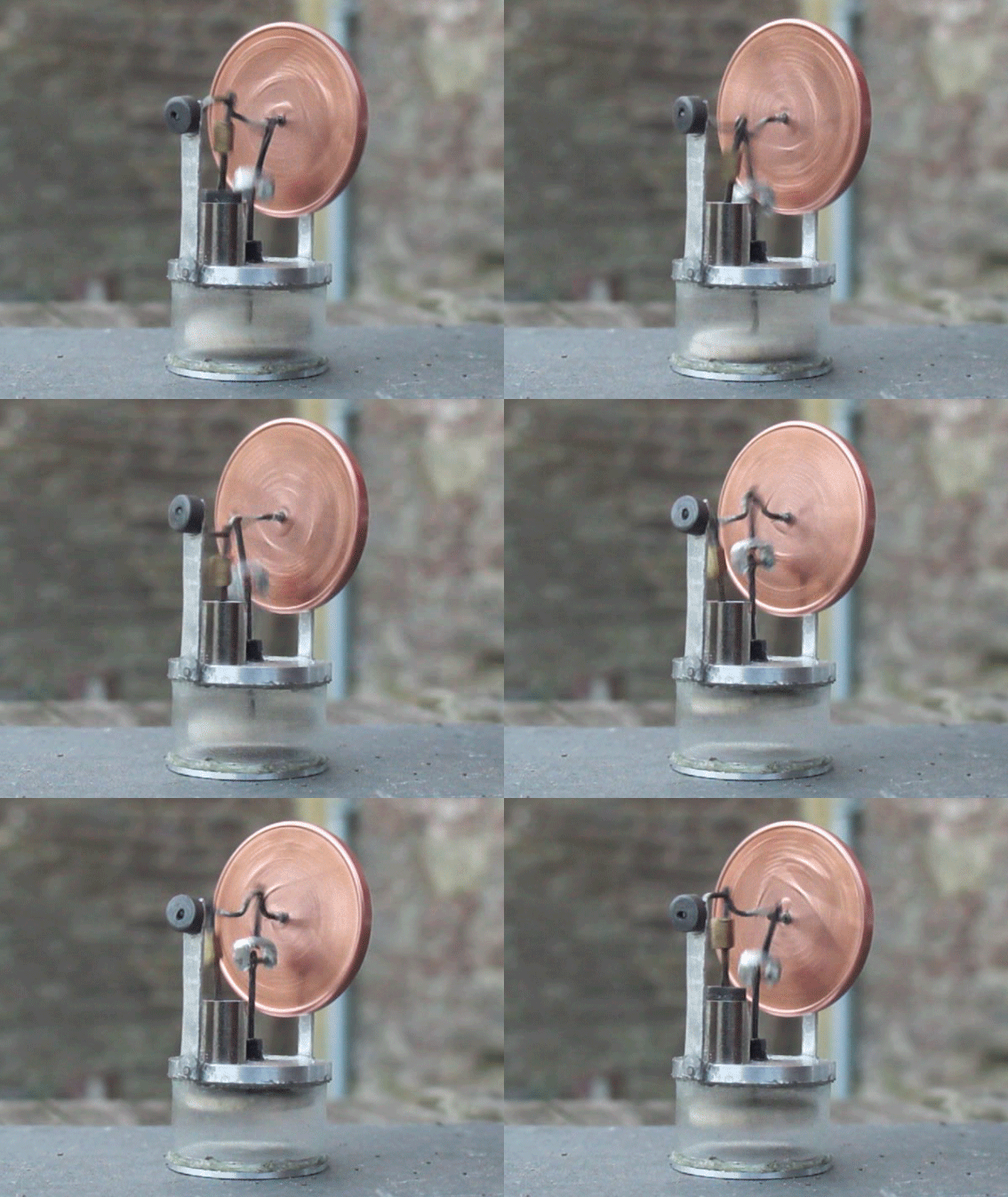
So a weekend lost, perhaps, but lessons learned and thanks to the power of television - or in this case, the internet - we can pretend that it runs by watching a looped gif of it turning over. Marvellous.
