
Melting KiCad, part 2
30 Jan 2022Progress: Complete
For some context on why anyone might want to melt KiCad, see part 1 of Melting KiCad.
KiCad 6 is finally here, bringing with it a bucketload of new features and improvements. You may notice that the user interface now supports Endless Pan, also known as Continuous Drag, or Cursor Warping. If your mouse reaches the edge of the window or the edge of your monitor while panning, it's no longer a hindrance. Once you've experienced it, it's hard to live without it. Naturally the idea was stolen from Blender, and contributed to the KiCad code base by none other than yours truly. In the process, we also fixed some irritating interface bugs in the Windows build. It might not be perfect, but Endlessly Panning in KiCad is remarkably satisfying.
However, the real feature we were all waiting for in KiCad 6 was native support for rounded traces. They have finally arrived! But before we go bid farewell to the subdivision-based track rounding plugin I should mention that what we have here is limited support for rounded tracks, and it's still in its early days. It's good enough to manually round a couple of corners on one track, but a far cry from being able to melt an entire board.
We were promised a new python API in KiCad 6. That's been postponed until KiCad 7, but unsurprisingly the SWIG-generated stuff doesn't quite match that of KiCad 5. Various names and methods have changed so the round tracks plugin will need updating before it can run in version 6, and if we're going to update it, we might as well take this moment to make it better. More melty!
Fillet Tracks
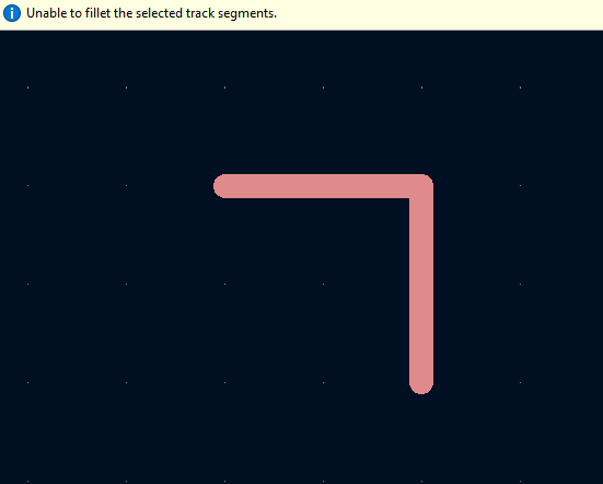
In KiCad 6, if you select two connected tracks, right click, choose "Fillet Tracks", enter a radius and an arc will be formed.

You can click and drag on the arc to change its radius (but not drag its endpoints).
Ideally, you would be able to select all and hit Fillet Tracks, and the whole design would melt, but that doesn't work for a number of reasons.
First, if the radius is too large for the selected tracks, it throws a warning and refuses to create the arc.
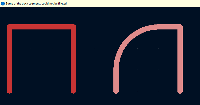
Second, if two two corners are in close proximity to one another, only one of them will get rounded.
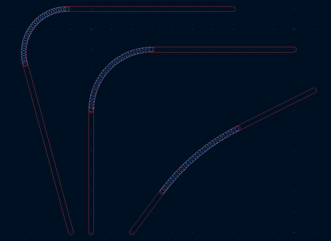
Third, the radius is not adjusted based on track angle. This becomes most obvious when you have very sharp angles. In the following screenshot, the blue traces are the original tracks, the green traces are the result of my subdivision-based track rounding plugin, and the red traces are the result of Fillet Tracks. In all cases, the radius parameter was set to 3mm.
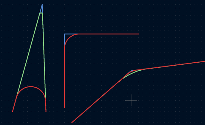
In the 90 degree case, both rounding methods result in the same shape, but for the very sharp angle on the left, blindly using a 3mm radius has eaten up a huge amount of the shape. In the gentle angle on the right, a 3mm radius fillet produces almost no rounding effect at all.
A fourth reason the filleting is unsatisfactory is that T-junctions (or higher-order multi-point connections) are ignored entirely.
Clearly, the best course of action is to update the subdivision-based track rounding plugin to generate melted designs using the native arcs, solving the above problems in the process. Ideally, running the plugin on a design should produce the same output (visually) with either method. How hard can it be?
Making arcs
The new track type, PCB_ARC, can be instantiated in a few ways. The method used internally when you hit Fillet Tracks is to first create a SHAPE_ARC, define its radius, and make sure it's tangential to the tracks at each end. The PCB_ARC is then instantiated from this SHAPE_ARC.Unfortunately, the python interface does not let us get anywhere near SHAPE_ARC as far as I can see. We can read the generated properties of a PCB_ARC such as radius and angle, but when creating a new PCB_ARC, the only parameters we can set are StartPoint, EndPoint, and MidPoint.
The start and end points are easy enough to figure out – just shorten the tracks leading up to the intersection. The midpoint requires some trigonometry.
The midpoint needs to define our radius, but also needs to align the arc so that it's tangent to the tracks leading up to it – otherwise, it won't be adjustable afterwards (and would look wrong).
The answer, naturally, is a weighted average of the points based on a cosine factor. Since it was bound to be something along those lines, I just guessed at what it might be. It either works perfectly, or comes out completely wrong, so oftentimes it's fastest to make a few guesses before resorting to drawing diagrams. Neat.
Irritatingly, though the new arcs were obviously tangential (and the wrong radius, but we'll deal with that later), the interactive adjustment for their radii wasn't having it. At first I thought this was a rounding error, but simply closing and re-opening the file fixed the problem. It seems there is some step which reassesses whether the arcs are aligned with the tracks that wasn't automatically called. Running pcbnew.UpdateUserInterface() was enough to fix it. My earlier attempt, running the ubiquitous pcbnew.Refresh() led to a collection of glitches, with the arcs being impossible to remove. I expect these teething problems will be cleaned up in future releases.
Matching radii
KiCad designs are not the only thing has been melting around these parts. My brain, too, it seems, has melted.The radius correction factor is going to be another trigonometric equation of some disposition, and while I got lucky on the previous one, guessing it correctly almost immediately, this time I looked destined to resort to drawing triangles on paper again. Lord, spare me the triangles on paper!
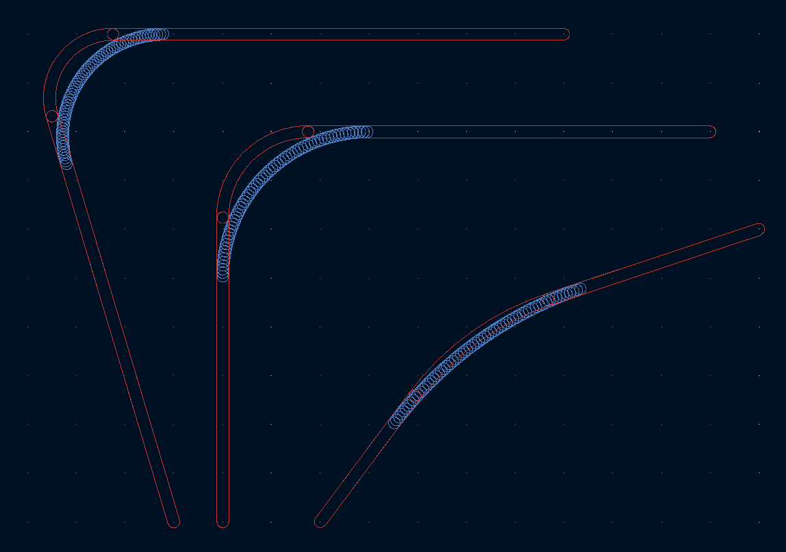
Instead, I took an experimental approach. We visually align a bunch of arcs with their subdivision-based counterparts at different angles, and write down their coordinates in a spreadsheet. This lets us plot intersection angle against correction factor (the ratio of the expected, and generated, radii). From here, it's a lot easier to guess what trigonometric equation lines up with the dots.
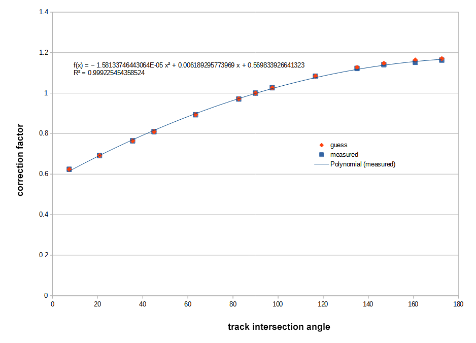
The "helpful" polynomial fit to the curve obviously provides no insight at all, but the answer we were looking for was ( sin( angle/2 ) +1 ) * constant, where the constant turned out to be 0.585786...
The process was:
- This shape is obviously part of a sinewave.
- It's a quarter segment, so it'll be a function of half the angle
- There is an offset and a gain adjustment, somewhere in the region of 0.6 for each
- The offset and gain are the same, so it's a constant times
sin(angle/2) + 1 - At 90 degrees the factor must be 1 by definition, so the constant is
1/(sin( 45 degrees )+1)
The reason I say my brain has melted is that the constant, 1/1.707... was already in use elsewhere in the same piece of code. D'oh!
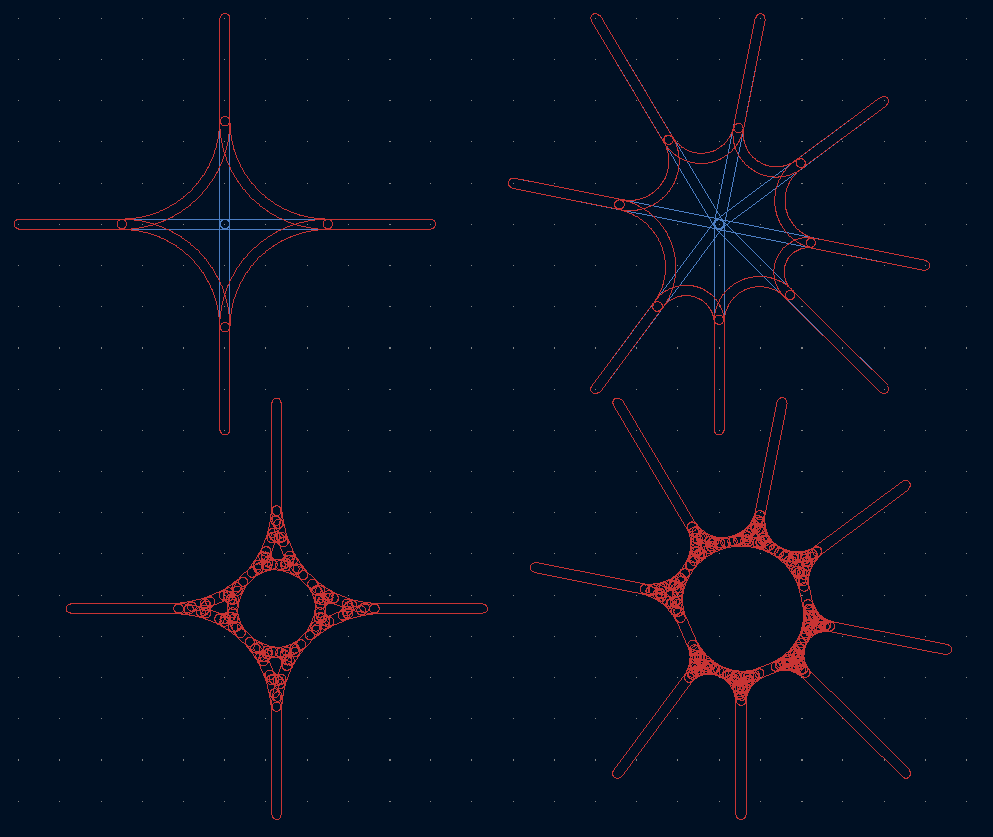
Tricky bit over, the next challenge is tight corners. When faced with a square (and a radius parameter larger than the size of it), the subdivisions produce a circle. The first chamfer cuts off at about (but not exactly) a quarter of the way along an edge. Eventually, all that remains of the original track is a single point in the centre.
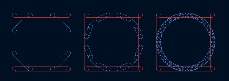
With native arcs, we go straight to this end result: never shorten a track by more than half its original length; if shortening from both ends, delete the track and tie both arcs to the centre point.
Pleasing!
T- and X-Junctions
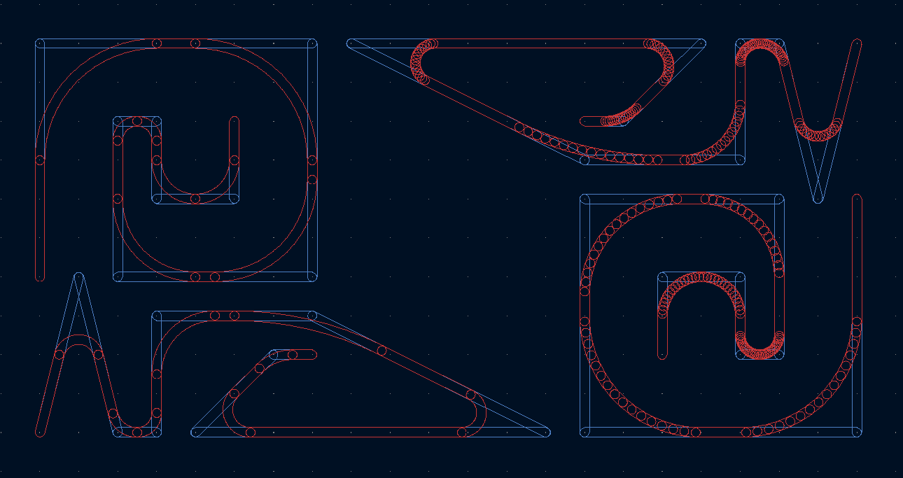
T junctions are a valid use case.Higher order junctions, not really.
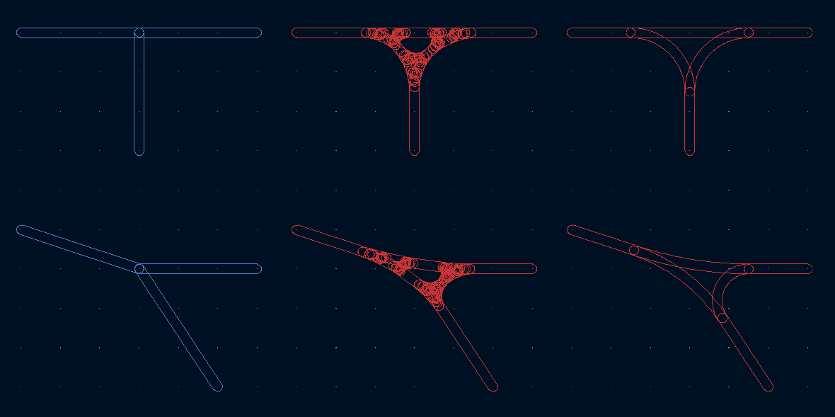
These junctions just about work. There is still some uneven-ness in both cases because of the order in which it processes the tracks. If ever I decide that multipoint junctions could be useful on a PCB, I may try and improve on this.
Teardrops torn
For the full melty experience this track-rounding plugin needs to be combined with the teardrops plugin, which we contributed to in part 1.Unfortunately, with the native-arc upgrades, we've now broken compatibility with it. It assumes all tracks are straight, so native arcs result in erroneous shapes.

Luckily, I don't think it's particularly hard to solve this problem. We just need to figure out the position and vector of a point a certain distance along the arc.
The interface for adding arcs is very limited, but for fetching derived properties of the arcs it's quite expansive. We can grab the angles (start, end, and the included angle (curiously all measured in tenths of a degree)) and the radius, arc centre, and the actual length, not just the distance between endpoints. I could bore you with the details, but that's everything we need to solve the problem.

It's a little bit trickier in the followed tracks case, a kind of hybrid between the old follow-tracks meant for subdivided arcs, and the new arc format, but because GetLength() returns the right amount, most of the code can remain unmodified.
At the time of writing, I've submitted another merge request to the teardrops repo, but that plugin is still in the process of being ported to KiCad 6.
Conclusion
Work on the plugin is still on-going, but it's all boring stuff like fixing edge cases and trying to prevent segfaults.One notable bonus in KiCad 6 is the addition of a "Plugin and Content Manager" – a repository of plugins with a single-click install. Since it has nothing to do with melting, I won't blather on about the process, but hopefully in the near future you should be able to install the Round Tracks plugin from within the plugin manager.
In case you missed it, the github repo for the plugin is here.
Update (14 Apr 2022)
Re-live the adventure in video form: