
Light comms on the 003
31 Jul 2024Progress: Complete
Is it possible to add optical wireless communication to a circuit, without adding any more components to it? Let's find out.
Preamble
I don't have much amateur radio experience (none at all, specifically) but I do enjoy chatting to various folks who've delved into the deepest niches of the subject. Regular amateur radio is too mainstream, see, so many enthusiasts carve out their own subcategories.A comedic example, parked nicely on the thinnest wedge of the venn diagram, is the HamFurs – people who do amateur radio while wearing fur suits. While it isn't my cup of tea, I love that such a group exists. They seemed like nice people when I chatted to them.
Most subcategories do relate to radio in some way though. Some years ago I talked at length with a guy doing AmSat (amateur satellite tracking). He was listening to a very high frequency signal, I think it was 40GHz, and I specifically remember the antenna looked like a plastic disk. At such frequencies, the waves can be focused the way a lens focuses light.
Another niche I was only recently alerted to is the Nanowave group. The goal here is to communicate in the hundreds of terahertz range, i.e. visible light. That might sound a bit dull, given the existence of infrared remotes, and the ubiquitiy of optical fibres, but the aim with nanowave is non-line-of-sight communication over many miles via cloud bounce.

The light shined on the clouds isn't visible to the naked eye, but by clever modulation and even cleverer signal recovery algorithms, surprisingly large distances have been achieved. A neat thing about it is that you don't even need a license!
Many GPS modules, even cheap ones, can track signals at ludicrously low signal levels. I have some here that can track satellites at a received signal strength of -167dBm. It's hard to believe power levels could even go that low. This is managed partly by the way the signals are modulated, they have a high symbol rate (1Mbps) but a very low data rate (50bps). A similar performing ham radio technology is WSPR, which can recover signals from far below the noise floor.
I guess I enjoy the idea of taking this sort of technology and applying it to the pointless, yet fascinating, challenge of light communication via cloud bounce. However, I'm rambling, and today's project doesn't really have much to do with this, except for the relevant fact that we're communicating with light.
A light amplifier
Recall my attempts at an automatic LED. There I used an STM32 and some hackery to automatically dim an LED based on ambient light levels. It's no secret that LEDs can work as light sensors, the main problem is that they're just not very good at it.When we talk about light communication, there's a definite appeal to using the same component as both transmitter and receiver. For one, the optical alignment for bidirectional signalling is going to be perfect. But the primary appeal to me is the reduced component count.
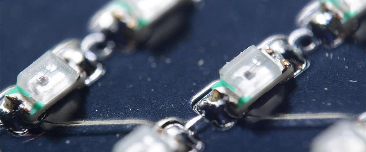
I've produced a few different pieces of LED jewellery, and one of the tricky problems is giving the right level of control over the flashing patterns. Sensors can be used for reactive patterns (microphones, or temperature/heartbeat etc) but often we want to provide a way for the wearer to directly control it. The simplest option is a small switch to cycle through modes. Adding a bluetooth antenna is not impossible, possibly even using the chassis as the antenna, though in the case of the industrial piercing the chassis was used as one of the connections to the battery. I considered a hall sensor, which could be very small, responding perhaps to a magnet embedded in another bit of jewellery, but at the end of the project I felt like the best direction to go in would probably be an infrared receiver.
Infrared is arguably nanowave comms, and TV remotes generally have very good performance, so let's talk a little about how they work. An infrared LED produces light at say, 1μm wavelength, or about 300THz. In a sense, this is our carrier frequency, and the infrared receiver has a filter window over it, which blocks light that isn't in the vicinity of this wavelength.
But the IR signal is modulated with another carrier signal, this time in the kilohertz range (usually 38kHz, but it varies). There are a few reasons for this, one is that directly modulating the light frequency is technically difficult, but turning an LED on and off at kilohertz speeds is easy. Another reason is that the receiver is going to have a response time based on its capacitance. The IR LED could be modulated at many megahertz, but decoding this is going to need a high bandwidth sensor (expensive). To keep costs down, in consumer IR these kilohertz frequencies are used.
The primary reason for the kilohertz carrier is for noise immunity. In addition to the IR filter window, we can bandpass filter for the kilohertz carrier. There is a lot of stray IR light in the world, but natural sources of light aren't going to be modulated in a way that gets through this filter.
Finally this double-carrier is modulated with the data to be transmitted, usually with simple on/off keying, giving us a data rate of maybe 100 bits per second.
Decoding the IR signal has a few important steps. It is extremely unusual to roll your own demodulator, there are plenty of parts available which are a single component with sensor and demodulated output. Here's a block diagram from the datasheet of one of them:
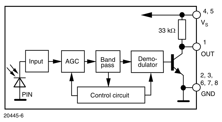
The input stage is a transimpedance amplifier, the PIN diode is used for its low capacitance.
The AGC is probably the most important part to get reliable operation over a wide range of distances. While the PIN diode is a much better light sensor than trying to use an LED, there will only be a certain range of light levels where it functions correctly. Too much light and the output will saturate, too little and we won't have a signal. The AGC, automatic gain control, adjusts the gain to give us the maximum dynamic range.
Most IR receivers are physically large, the very smallest ones I could find are Vishay TSOP574... series, which are surface mount in a 4x4mm package. That is very small, and I will probably try and work one into some jewellery at some point, but it's still a lot bigger (and more power hungry) than a single LED. We're not going to be able to make anything nearly as good on our own, but can we make something good enough?
Op-amp on the CH32V003
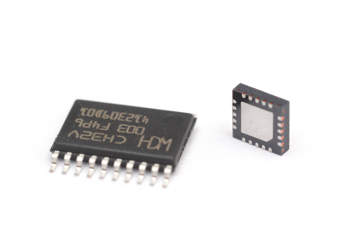
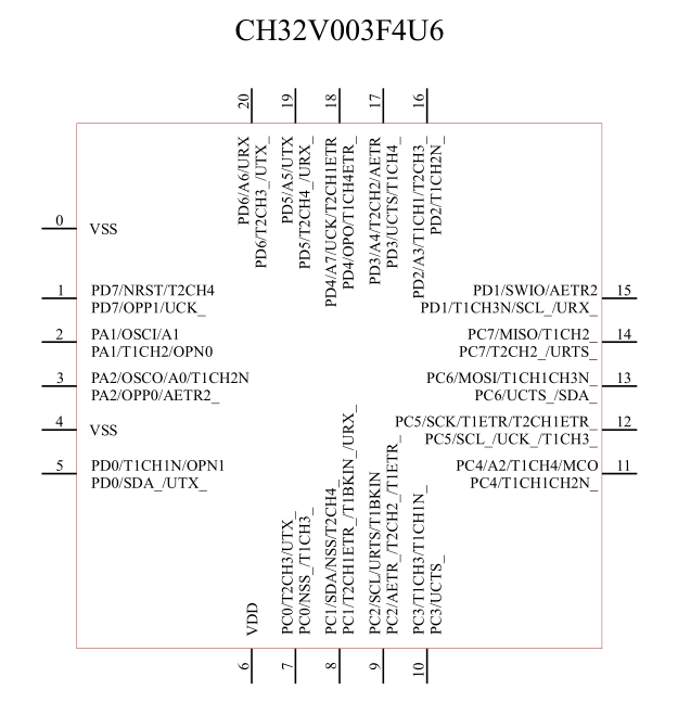
The CH32V series is the RISC-V line of CH32 parts. The CH32F parts that came first are essentially clones of the STM32F series and many features of the CH32V are directly inspired by them. I have been playing around with the CH32V003, an exceptionally cheap microcontroller, and much like many of the STM32 parts, one of its peripherals is a general purpose op-amp. I decided to have a play around with it.
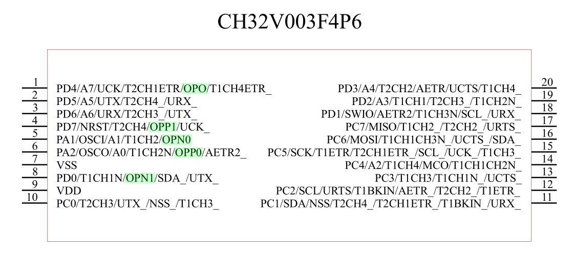
There is very little documentation on the built-in op-amp, presumably because there is very little to it. Just three bits within the Extended Control Register (EXTEND_CTR), to enable it and toggle whether the alternate pins are used. Within the system block diagram we can see the opamp is connected to those pins I've highlighted in green above, and also potentially to the ADC and TIM2.
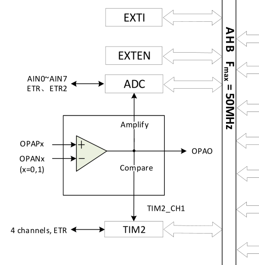
I'm not sure if there's an internal connection between the op-amp output and the ADC, but both are connected to PD4, which is analog channel 7. The output voltage is of course exposed on PD4, since you wouldn't be able to build a negative feedback loop without it. I have not looked into using it as a comparator (open loop) and whether you could use PD4 for something else in that case.
The final bit of info is some electrical characteristics listed in the datasheet (not reference manual).

Looks a lot like an op-amp. The output is rail-to-rail, which we would hope for, if we're planning to run this from 3V.
The reason using the built-in op-amp for this is so appealing is that it can be switched in and out of the circuit, the same way the pins can be reconfigured as GPIO. The bare minimum we need to add for a transimpedance amplifier is a single feedback resistor. Our first attempt looks like this:
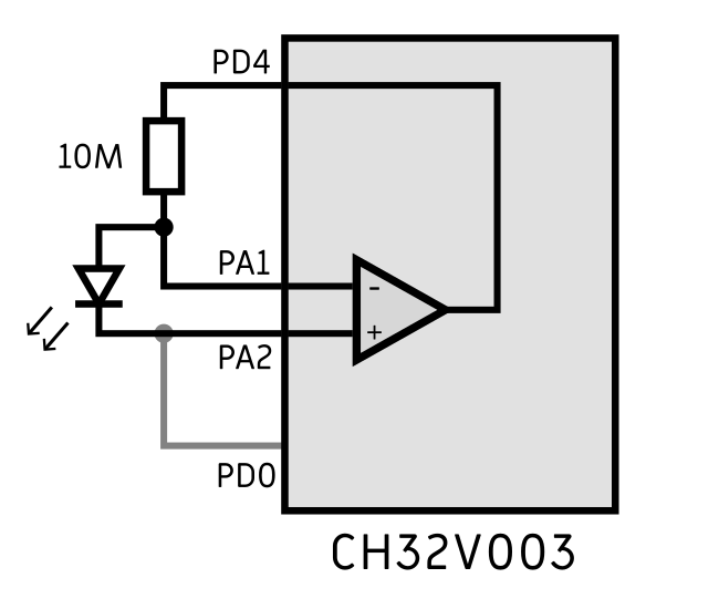
The non-inverting input of the opamp needs to be held at a fixed voltage for the thing to work. I initially tried simply configuring PA2 as an output, but I wasn't convinced this worked correctly. We could tie it to ground (or VDD) but it's much more preferable to have software control of the connection, so I wired it to the neighbouring PD0.
When detecting light, the LED can optionally be reverse biased, which improves response time, but our concern is more about voltage levels and saturation at the output. The supply voltage is between 3V and ground. If we've wired up the circuit so as to produce a negative voltage output we won't get any output at all. By setting the cathode to VDD (i.e. PD0 high) we bring the output into a usable range.
To illuminate the LED, we set PA1 and PA2 to outputs, with PA1 high and PA2 low. You'll notice there's no current limiting resistor there. I frequently wire LEDs up to microcontrollers without limiting resistors, the "on" resistance of the output FETs means the current is predictable and usually tolerable. Even if this current is higher than we'd like, we can just drop the duty cycle.
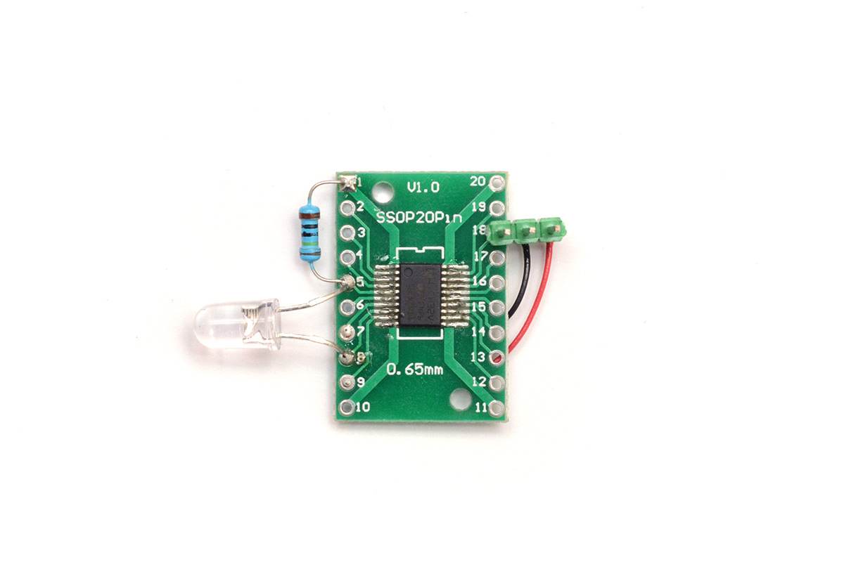
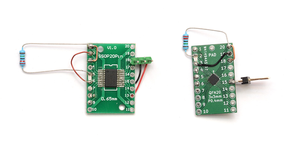
Here's a picture of my first board (that doesn't exactly match the schematic above, but I played around with various different configurations):
First results
The feedback resistor sets the gain on the amplifier. I started with 1MΩ, then 10MΩ and 22MΩ (biggest value I had to hand).I configured the ADC to spit out values over the debug connection and shined a torch on the creation.
It certainly isn't the most sensitive detector in existence, but at the highest gain the effect of shining a torch on it is quite obvious up to about 20cm (eight inches) away. One very noticeable thing is that the through-mount LED is extremely sensitive to direction. I suspect this is a physical effect with how light interacts with the crystal structure. If it's on-axis the sensitivity is quite high, but even slightly off-axis and it drops to piss-poor.
I switched out the LED for a surface mount one. At the very least, problems with acceptance angle and focusing shouldn't matter here, as the plastic moulding is flat and in close proximity to the LED crystal. Subjectively, this does feel a lot less sensitive to incidence angle.
Overall, for the cost of adding just a single resistor, getting a light sensor that can detect a signal over a few inches still feels like a win. It's possible we can up the gain further still. Ideally, we'd have adjustable gain, which would let us do our own AGC if the thing does get swamped by too much light.
One option is using the alternate pins of the opamp to have two distinct gain levels. Another option, if we have multiple LEDs in the circuit, is connecting them in parallel to boost the signal. If the circuit has a matrix of LEDs (likely) then we could potentially wire a whole row of them up to the circuit. The column drivers could selectively be biased, to control which LEDs are part of the amplifier circuit.
Before we get ahead of ourselves, let's try and get some communication going over this channel.
Second board, and more boards
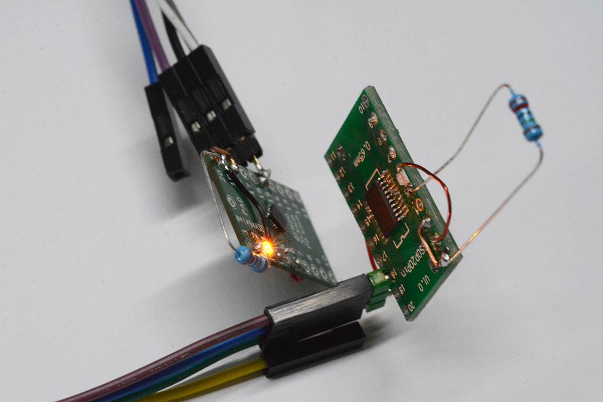
For communication we'll need two circuits, so I wired up another CH32V003 with an LED and a resistor.
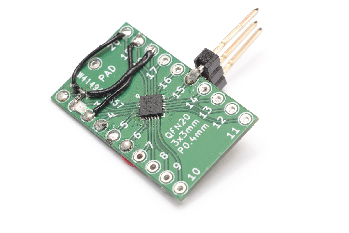
I initially wired it up incorrectly. This is on one of my own 0.4mm QFN breakout boards but the snag is that the pinout of the different CH32V003 packages aren't the same.
I was getting a bit sick of wiring up that same three-pin header each time too, so this pushed me over the edge to make yet another breakout board, this time explicitly for the CH32V003. While the pinouts between the packages are not the same, the internal die is, so the order of the pins around the packages match. With some creative thinking, it's just possible to construct a single footprint that supports both packages.
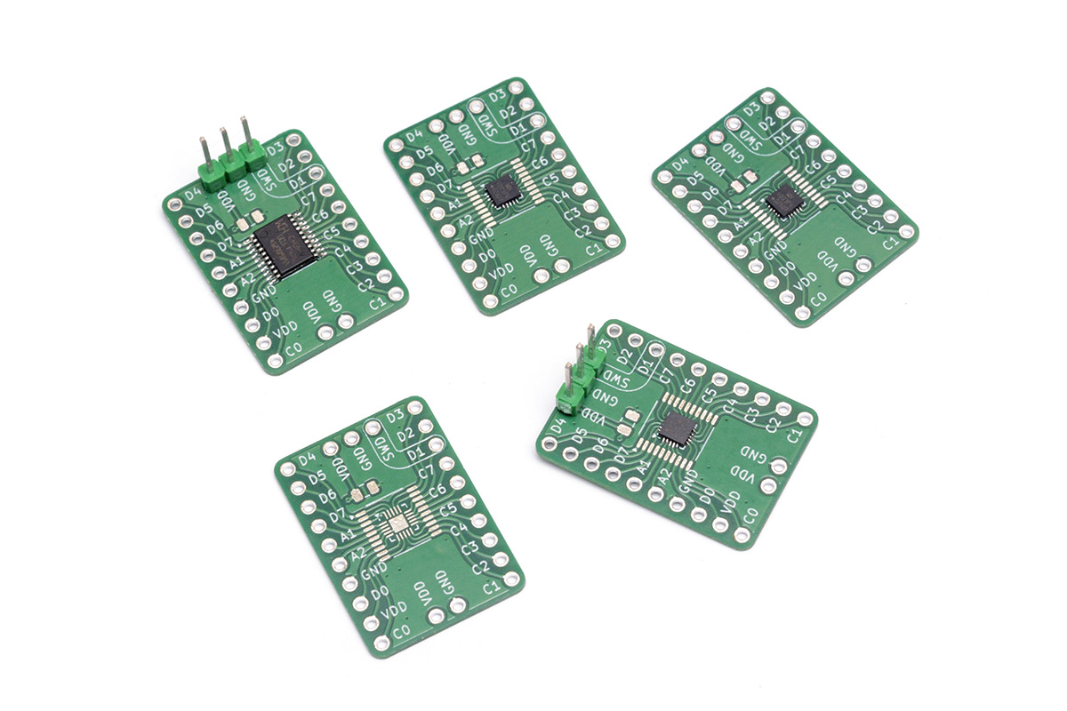
This means we can label the pins semantically instead of by number and we're less likely to make mistakes. I also put a couple of capacitor footprints on there just in case.
The kicad files for this design were added to this repo.
With that narrative diversion complete, let's jump back into the light comms stuff.
Reception logic
I now had one board blinking its LED and the other board detecting it. I made sure both LEDs were the same wavelength, which happened to be a nice orange colour. It's possible that different colour LEDs have different sensitivity. I would imagine blue or white LEDs would behave worse, as the phosphors emit light at a longer wavelength than the bandgap. I have not actually investigated yet though.
The ADC reads 0x3FF when the circuit is in the "dark" although it doesn't seem at all sensitive to the room lights. When the other LED faces it, the reading dips and eventually gets to zero when the two LEDs are almost touching. In this setup, with the surface mount LEDs, the largest distance a signal can reliably be detected is maybe three inches.
The CH32V003 has no floating point unit or even a hardware multiplier, but it does run at 48MHz so there's a fair amount we can do. The initial plan was to do something like this:
- Sample the ADC at, say, four or eight times the carrier frequency
- Perform a moving average filter (just additions and shifts) and subtract this from the signal, to remove the DC offset
- Threshold the signal into a binary stream
- Within a moving window, hunt for our carrier frequency. Similar to how one might approach a phase-locked loop. The presence (or absence) of the carrier represents our output data stream.
It certainly should be possible to achieve as good a performance as an off-the-shelf demodulator, if the sensor is sufficiently sensitive, and the dynamic range is available. However, when the output flatlines at anything over six inches away, all that filtering for noise immunity does seem somewhat pointless. Again, it may be possible to up the gain further, perhaps 100M or 1GΩ as the feedback resistor, but this probably isn't going to help. The open loop gain is stated as 105dB which is about 1.8x10⁵. There's only so much we can do with a single opamp. I did try the circuit with no feedback resistor at all, and the output was consistently zero, so whatever leakage currents we have, they aren't in a useful direction.
The point I'm getting at is if the boards have to be so close together for it to work, why even bother with analog signal recovery? We can forget the ADC and let the GPIO input be a simple threshold of signal/no-signal. The analog reading drops to a logic-low level when the two LEDs are about 1cm apart. In this case, there is pretty much zero chance of ambient light affecting things. Even in direct sunlight I think one circuit board is going to shadow the other.
I slightly rewired the circuits to connect up the existing UART hardware. This requires a couple of jump wires but the component count is still just one LED, one resistor, and the CH32V003.
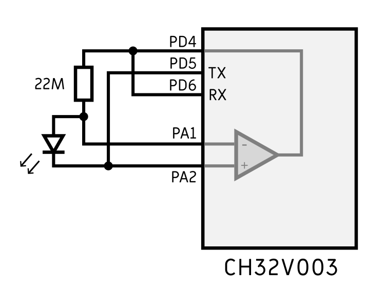
The ADC can be disabled or ignored. In reception mode, the op-amp produces a signal on PD4 which is then directly connected to the UART RX pin, on PD6. The output signal is high when in the dark, and drops low when light shines on the LED. UART reception is idle-high and the start condition is low, so this works perfectly to automatically wait for reception.
In transmit mode, PA1 is high and PA2 is floating. UART TX on PD5 is idle-high, active-low, so when the UART signal drops low the LED will illuminate.
With this hardware arrangement, we can simply use the UART hardware to transmit and receive as if there was a physical connection between the boards. On condition they are within 1cm of each other of course.
UART tests
The results are surprisingly good. At first I tried transmitting at 115200bps, which printed this sort of nonsense:
@5~�PEsispEc            @pB@@@B@@BB@BB@BB@BB@B@@B@B@BB@B@EccsTesthi t�n��es�~ ��
���߰T�� �Esii@b+B@B@B@@@@HB@BHBHBB@B@B@B@BB@b@l+                             c@+
@bcl+                                     bbb+@bbb@Bc#B@@HBB@BB@HBBH@BHB@@@@BB@H
@HBB@B@BHBB@B@BB@@                                               B@@B@B@B@EcistP
es!isttcHB@bPEsistTes!hi tTes!ise Pessst!@EcaapTes!is !Tes!�v��o��es istEcaapAb+
@cAl+
 HHHB@B@B@B@Ec@ceTes is t�~��������~�ecistbc#BB@HHH@BB@@B@@@Hbc
                                   es!���T�߰�߰�����EsistB@BB@B~~��es!hs tPesist!
@E@@B@B@B@HHBBHBB@BB@BBB@BB@BBB@BBH@BH@@H@@@@Bb
                       Tes!iiF�TesFo�e~~~�����PecistB@bb@"Ac+@Ec`apb@
     B@@B@@Bb#B@B@B@B@@cb`@@#B@B@B@@HBB@B@Bb@#
                       B@B@@B@B@@"B@@   B@BB@@         B@@bc              bA+bA#
Bb                      b@                        cAl+b@cA+
            B@Abal+                                        B@@bbl+bA+
The corrupted data is being interpreted as terminal escape characters which explains the formatting, but astonishingly you can make out some evidence of the original message.
At 9600bps the message seemed fine. Continuing the binary search I tried 48000bps:
 Test! Ti satet Test! hs s ts! Pecphsits!@b`Ac@pD`@b`@b`b@b`@b@@`@b`@b@@`@b`@@@`
@b`@b@@`@b``b`@b@b``b`Ec@b`@b@@`@b`@b@@`@`@b`@@b@`b@b`@b@b@b@b`@bb`@b`@b@@`@b`@b
@@`@b`@b@b@`b@b`@bb@`b@b`@bb@`b@b`@bb`b@b`AcApc@b`@b@`@b`@@@b@b`@b@`@`@b`@b@@`@b
`@@b`b@b`@b@@b@b`@@b@@b@b`@b@@b@b`@@b@`@b`@bb@`b@b``b`bp@b`@c`Db@b`@b@b@pc@b`@bb
@`b`@b`@b@@`@b`@@@@`@b`@b@`bEcp`acApsp@b`@cA@`@b`@cAbpTest�|n�est! hi sats!Test!
 hi sats!Test!Ths s ttTest!Thsi  ts!Test! hi sats!Test����est! Ti satst Test! hs
 savnTen��o�n�Test!hsi  ts! Test! hi satet Test! Ti satst Test! hs s es!Test! hs
 saes!Test! Ti sats!Test!Ti   et TTest!�~~oTest! isi  et Test! Ti sats! Test! hs
i  st Test! Ti satt Test! hsis et!Test! hsi  et!PestThsiatst Pest!Thsi  es!Test!
 hi  ts! Pesp! hsi  et!Pesp! hs s et PEcp`ssepEcp`acApEpP@cp`caEpEcp`ccEpP@c``ca
cpcP@c``caEp@c``acApcEcp`acApcpEcp`cEpP@c``ccApEpEcp`ccApcPecphsietPEctTii  et P
espPisietPEsp`si et AcpP`ssAppAcp@acApc@b````E`@b```bApcp@cp`ccApsTest!Tis�v�o�T
est! Ti sats!Test! hs saet Pest! hsi  et!Test! Ti sats! Pest! hs s et PEsthssaet
@Ec``cAEc@Ecp`ciEp@b```b@pcAcpPacApsp@c`@baE`@b`@@bAA`@b`@@b@`b@b`@@b@`b@b`@b@@`
Ebp@AcApc@b`@ccA`bPEcp`aiAts
It's interesting that the letter T (binary 0b1010100) is being transformed into the letter P (binary 0b1010000).
Finally we tried 19200bps which also seems fine. It still corrupts as we pull the LEDs apart and together:
is a test! Test! This is a test! Test! This is a test! Test! This is a test! Tes t! This is a test! Test! This is a test! Test! This is a test! Test! This is a t est! Test! This is a test! Test! This is a test! Test! This is a test! Test! Thi s is a test! Test! This is a test! Test! This is a test! Test! This is a test! T est! This is a test! Test! This is a test! Test! This is a test! Test! This is a test! Test! This is a test! Test! This is a test! Test! This is a test! Test! T his is a test! Test! This is a test! Test!�xys�sTest!`sTest�TesTes|Tes}�TeTest! This is a test! Test! This is a test! Test! Thisis a test Test! This is a test! Test! This is a test! Test! This is a test Ect ThIs is a test! @b` This is AdEc t! Ect This is a test! est! This is a test! Test! This is a test! Test! This is a test! Test! This is a test! Test! This is a�est!`Test! This is a test! Test! T his is a test! Test! This is a test! Test! This is a test!<Test�Ten�~Tes|���n�Te s|Test�s�s|�Tes~�Test! This is a test! Test! This is a test! est! This is a test !Test! This is a test! @@bp P@AcAcA`Ab`@c`@@bAb@`@bp @b`his IcAdEc`Test! HAc i s adest! EsdThis is a tEsd Est! This is a test! est! This is a test! est! This i s a test! Test! This is a test! Test! This is
With the two LEDs sufficiently close, the message gets through intact, so this seems like a comfortable speed. It also ties in nicely with the consumer IR frequencies being around 40kHz.
One of the ideas I had been working towards here was to use the UART hardware for our secondary carrier. We could transmit only bytes of 0b10101010 which would form a pulse train similar to the consumer IR transmitters. The receiver would have to throw away any bytes that aren't 0x55 or 0xAA and the data would be based on the timings between bytes. While this probably would give us a lot of noise immunity (and decimate our data rate) given the integrity of the messages above it doesn't really seem worth it. A better option would be to simply construct a packet format with a lot of redundancy and error checking. Perhaps send the same data again but with all the bits inverted, and then a checksum.
As it is quite short, I think I'll post the full source code for the above experiment here, but don't go away – the story continues after the break.
#include "ch32v003fun.h"
#include <stdio.h>

static inline void enable_uart( uint16_t mode ) {
  USART1->CTLR1 = USART_WordLength_8b | USART_Parity_No | mode;
  USART1->CTLR2 = USART_StopBits_1;
  USART1->CTLR3 = USART_HardwareFlowControl_None;
  USART1->BRR = 2500; //19200 bps
  USART1->CTLR1 |= CTLR1_UE_Set;
}

static inline void enable_tx() {
  GPIOA->CFGLR &= ~(0xf<<(4*1));
  GPIOA->CFGLR |= (GPIO_Speed_10MHz | GPIO_CNF_OUT_PP)<<(4*1);
  GPIOA->OUTDR |= (1<<1);

  GPIOD->CFGLR &= ~(0xf<<(4*5));
  GPIOD->CFGLR |= (GPIO_Speed_10MHz | GPIO_CNF_OUT_PP_AF)<<(4*5);

  enable_uart( USART_Mode_Tx );
}

static inline void enable_rx() {
  GPIOD->CFGLR &= ~((0xf<<(4*4)) | (0xf<<(4*5)));
  GPIOD->CFGLR |= ((GPIO_Speed_10MHz | GPIO_CNF_OUT_PP)<<(4*5));
  GPIOD->OUTDR |= (1<<5);

  GPIOA->CFGLR &= ~(0xf<<(4*1));
  GPIOA->OUTDR &= ~(1<<1);

  enable_uart( USART_Mode_Rx );
}

uint8_t uart_rx(int timeout) {
  while (!(USART1->STATR & USART_STATR_RXNE) && --timeout);
  return timeout ? USART1->DATAR : 255;
}

void uart_tx(const char *buf, int size) {
  for(int i = 0; i < size; i++){
    while( !(USART1->STATR & USART_FLAG_TC));
    USART1->DATAR = *buf++;
  }
}

int main() {
  SystemInit();

  // Enable op-amp (default pins A1 and A2)
  EXTEN->EXTEN_CTR |= EXTEN_OPA_EN;

  RCC->APB2PCENR |= RCC_APB2Periph_GPIOD | RCC_APB2Periph_GPIOA | RCC_APB2Periph_USART1;

  while(1) {

    enable_rx();
    uint8_t x = 255;
    x = uart_rx( 480000 );
    while (x!=255) {
      printf("%c",x);
      x = uart_rx( 4800000 );
    }

    enable_tx();
    uart_tx("Test! This is a test! ",22);
  }
}
A note about baudrate setting. The formula to get the correct BRR value is a little involved, as it includes a bitfield for a fractional divider. In the ch32v003fun header there's a five-stage macro to calculate it, which originally I just dropped in, then output the calculation with a #pragma message for my own info.
As I write this up I figured it's really not that much trouble to make a spreadsheet print out the numbers. They should have stuck something like this in the datasheet. Assuming your clock speed is 48MHz, here are the USART_BRR values for common baud rates:
| Baud | USART_BRR | Error |
|---|---|---|
| 4800 | 10000 | 0 |
| 9600 | 5000 | 0 |
| 1440 | 33333 | 0 |
| 19200 | 2500 | 0 |
| 28800 | 1667 | -0.02% |
| 31250 | 1536 | 0 |
| 38400 | 1250 | 0 |
| 57600 | 833 | 0.04% |
| 115200 | 417 | -0.08% |
| 128000 | 375 | 0 |
| 230400 | 208 | 0.16% |
| 250000 | 192 | 0 |
| 256000 | 188 | -0.27% |
| 460800 | 104 | 0.16% |
| 500000 | 96 | 0 |
| 921600 | 52 | 0.16% |
| 1000000 | 48 | 0 |
Light bootloader for OTA updates
Consider a couple of recent projects, the badge and the LED matrix earrings, both of which use a CH32V003 and a matrix of LEDs. If I want to change what they display, the only option is to reprogram the chip, which is quite tricky for the earrings. Even the badge is awkward to update. If I hand them out to people, it would be nice if they could change what it does.So an admirable goal would be to use this light comm idea to update the animation patterns. I think the first question is whether this should use a dedicated device (a programming circuit, perhaps within a charging case) or generic light, say, from a phone. The circuit definitely responds to the torch light from my phone, but I don't think we can modulate that from an app (or can we? see below). Blinking the screen is going to be very limited in data rate, but I suppose it's an option. Another disadvantage to that is that it's unidirectional which could make the process even more tedious.
The second question is whether to do a full bootloader or merely update a data segment. The CH32V003 has 2kB of SRAM and 16kB of flash memory. It also has a separate 2kB of flash memory as a bootloader segment. From the factory, a system bootloader is present there which can be dumped, but it can also be erased and filled with your own bootloader. The code on the earrings is very short, maybe 1kB, but there's about 10kB of animation data too. We could dedicate an area of memory, say the last 14kB, to be data segments and rewrite these as we wish. The first 2kB would be left alone so there's no risk of corrupting the code and ending in an unrecoverable state. But this wouldn't allow us to add new modes.
Alternatively, we could write a proper bootloader that replaces the whole flash memory, but then we run the risk of partial or failed updates leaving the thing in a non-working state. There are plenty of workarounds, such as splitting the memory in half and always keeping a full copy of a working firmware image. A lot of the techniques target complex applications (say, you have a networking stack that wouldn't fit into the bootloader segment) and are probably overkill here.
In the case of the badge, perhaps all it needs is the ability to change what text is displayed, which would be a few hundred bytes at most.
Let us investigate the schematic for the badge.
![]()
![]()
Evidently I did not design it with this in mind, but we got lucky. There was only a 50% chance of having a row of LED anodes on PA1. It's labelled column 6. The output of the opamp is on PD4, or column 3, and the noninverting input is on column 7.
Obviously we could redesign the schematic of the badge if it comes to it, but I would really love to add this power to the existing badge by doing nothing more than adding one resistor.
Looking at the alternate pins for the op-amp, we can reconfigure the noninverting input to be on PD7, that is, NRST. Fantastic, as that pin is only used for the switch. The reset pin isn't used for debugging, and it's possible to reconfigure it to be generic IO. We need the noninverting input to be held at VCC. I already ruled out configuring it as an output, but what I found does work is enabling the pullup resistor. The op-amp should draw no current, so the pullup should keep it firmly at VCC. As a bonus, it doesn't short the chip out if you press the button. I tested both configurations: as a GPIO with pullup, or just as a reset pin with automatic internal pullup. Both work fine.
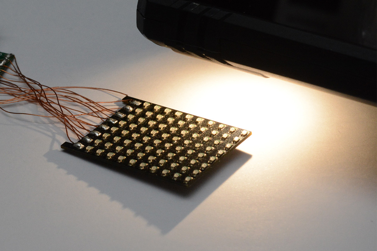
I dug out the dev board for the badge, and added our high value resistor between PD4 and PA1. Setting all of the cathode pins output high puts eight LEDs into our amplifier circuit in parallel.
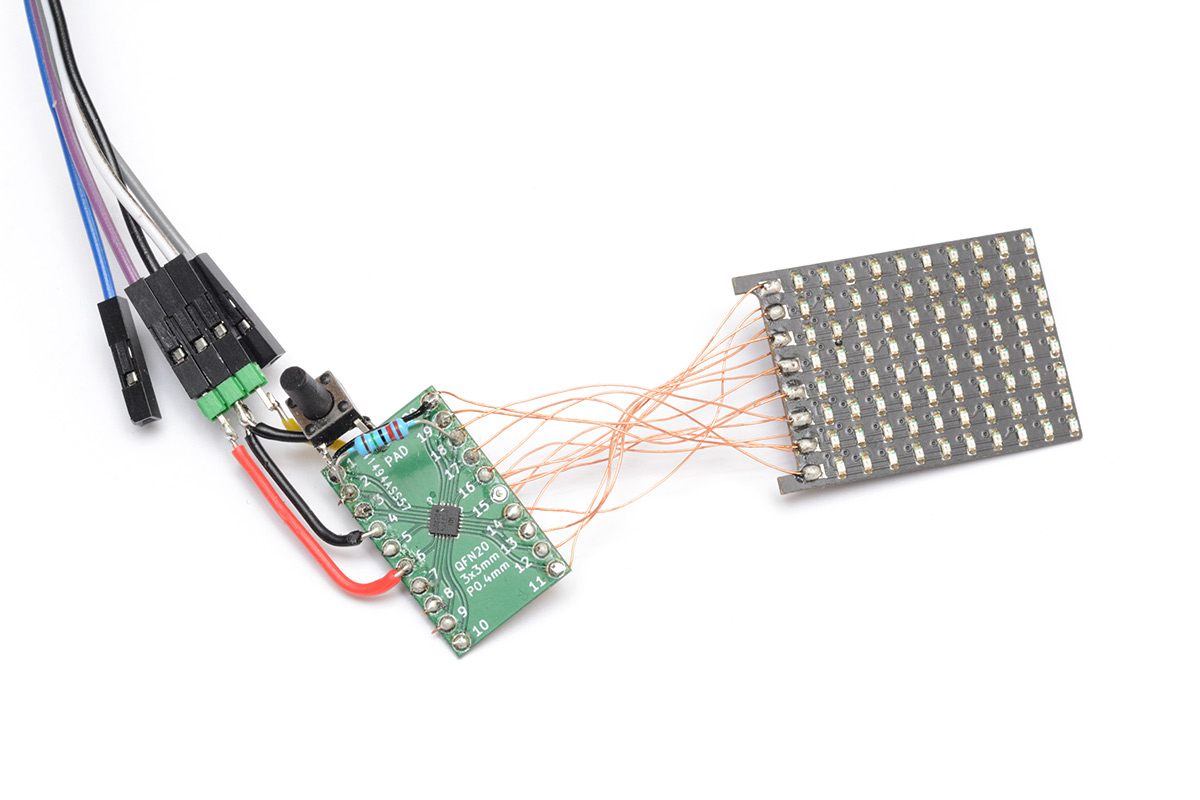
(Ignore the small black wire just above the resistor, it's only connected at one end.)
I loaded up my simple program to dump ADC values to the terminal and it took me a moment to figure out what was going on. If I shine the torch on the whole matrix, I don't get much of a reading, but as I sweep the torch over the matrix it responds quite significantly. This is because we have rows of LEDs connected to both ends of our amplifier. One of the rows is directly connected to the op-amp output, so any induced current is going to directly counteract our reading. I added some black tape over the LEDs that we don't care about:
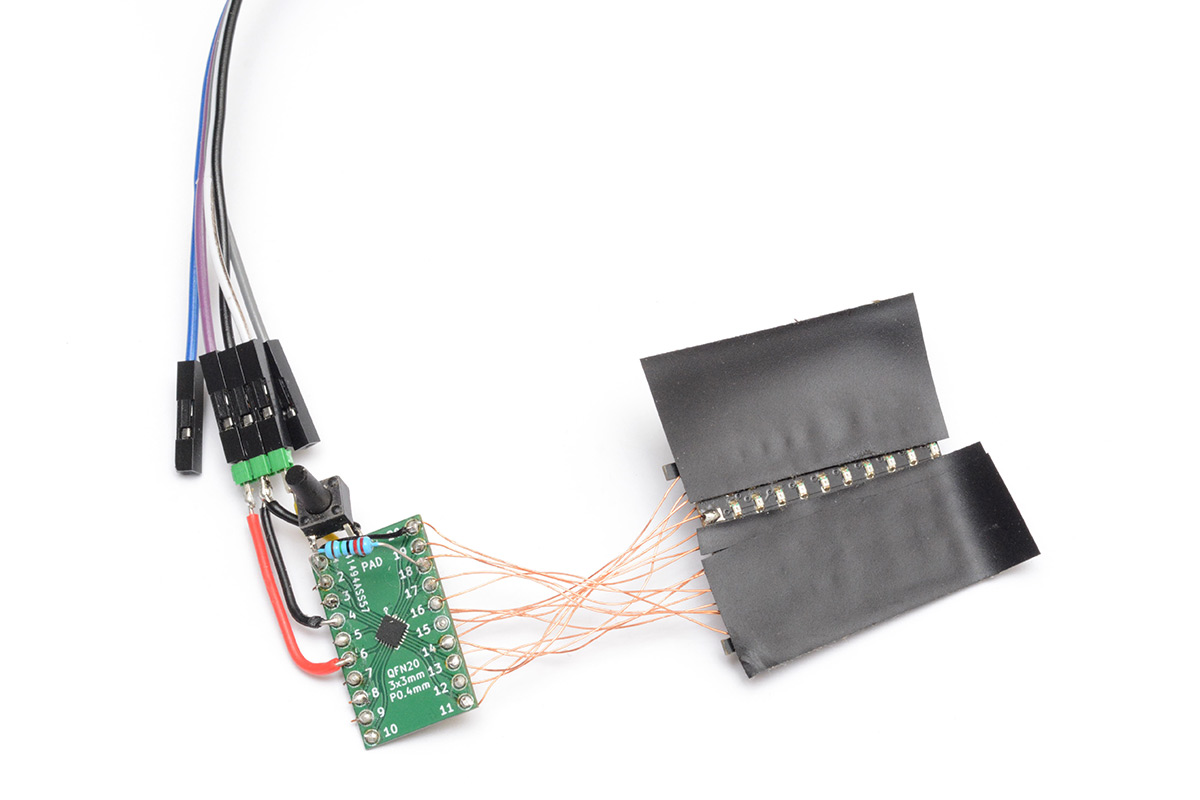
Suddenly the thing sprang to life, with dare I say, about eight times the sensitivity of the original circuit. I mean it's not going to win any awards but I can wave my phone torch and see the reading change up to about an arm's length away.
One row of LEDs is connected to PD4, the op-amp output. I unsoldered this connection and tried it without the tape. The reading became quite noisy, and still improved when I put the tape back on, so I think it's more than a single row of LEDs causing problems. Without significantly rewiring the circuit I'm not sure how we can get perfect sensitivity. As a compromise, we can use the alternate pin for the op-amp inverting input, which means the light-sensitive row is now at the edge of the matrix on column 8.
Without the tape, it's not too hard to aim a torch on half the matrix and get a clear reading. Hmm.
Light (very light) transmissions
I made a small program that I could run on a smartphone to flash a thin rectangle of the display. The idea is that we could ask the user to place the badge face flat on the screen, within a designated rectangle, and the screen would flash only in the region of the sensitive LEDs.Results were mixed. The phone screen needs to be on the highest brightness and the "night light" (blue light filter) disabled.
The biggest problem is that the capacitive touch screen is interacting with our measurement. When the circuit is held a few millimetres away from the screen, it reads fine, but if it's in direct contact the reading goes haywire. Perhaps using a desktop monitor instead would give better results. Overall, I wasn't too convinced this was a reliable way to update the thing.
I did some research and it transpires that controlling the smartphone torch from userspace is possible. Not just possible, but possible from javascript, at least on Android. The method is to request access to the camera, and then deep within the constraints there is a means to control the torch.
I made a program to blink the torch as fast as we can, and yes, it technically modulates. The shortest pulse possible was about 30ms, but it's extremely unreliable. The latency of updating it is bad, but the jitter is absolutely atrocious. Testing this on a Pixel 6a, every few seconds there's about 150ms of jitter. Part of this is because it's javascript, part of it is the OS and how they probably never expected anyone to want to do this.
If we can cope with a very low bitrate, at least it's easy to point the torch at half the badge and get a nice clean signal.
In javascript, I wrote the simplest program to transmit uart by blinking the torch at a glacial pace. The bit period is 200ms, so our baud is 5, or one byte every two seconds.
On the receive end, I wrote a software uart receiver. Even if we could configure the hardware uart to run that slowly, it's connected to the wrong part of the matrix.
Any faster than 5bps and it seems to regularly corrupt the data. Recovering from a frame error is quite tedious, perhaps it's worth adding delays between bytes to give it more chance to resync. However, the fact is, I now had "wireless" transmission from a smartphone to the badge.
It crossed my mind to use morse code. This would honestly be faster as an encoding, but it's limited as there's no case sensitivity. The encode/decode is also more effort than the simplicity of uart (which is just start/stop bits around the data). As we're sending ascii I reduced the uart to 7-bit packets, which gives us a 10% speedup in transmission.
The javascript program necessitates access to the phone's camera, so the possibility of bidirectional communication is not off the table. The fact we have to angle the torch at only half the matrix makes this a little less convenient though.
Optimisation ad infinitum
Hold on to your hats, because things are about to get exciting.To reduce the influence of the other LEDs, I dropped the gain of the amplifier, swapping the feedback resistor with a 1M. I confirmed it still worked, but the effects of doing this led me to poke around some more. After thinking about it for a bit, I got rid of the resistor entirely. This puts us into open-loop configuration, which is dangerous territory as it's usually highly dependent on random manufacturing differences, but the results this time were quite unexpected. It turns out that the feedback resistor had been suppressing a more dominant effect.
The columns of LEDs feed their tiny current into both ends of the amplifier. Without the feedback resistor, this turns into an optical differential amplifier. Essentially a comparator, with the output determined by which column is more illuminated.
Forget shining a torch a few inches away, the badge suddenly became sensitive enough to notice the shadow of my waving hand from the other side of the room. What's more, because it's a differential input, it's automatically compensating for ambient light levels. I took the board outside and in direct sunlight I get a clear signal as I cast a shadow across the badge. Despite being open-loop, it's not really behaving like a comparator, there's a very clear analog region while the face of the badge is evenly illuminated. Indoors, I can focus the beam of my torch from many metres away, and the output jumps from 0 to 0x3FF as it illuminates one side or the other.
Possibly the most pleasing aspect of all this is that we've eliminated the one extra component. That is, we've achieved a very sensitive optical differential amplifier on the badge with no hardware changes at all.
This differential mode is much more immune to noise, so flashing a message using the screen of a phone is now easy and reliable, with the effects of the capacitive touch screen drowned out. Compared to the jitter of the torch, the 60Hz refresh rate is very reliable, so data rates can be (comparatively) higher.
I don't fully understand what's causing this circuit to behave so well. With the feedback resistor in place, we had something like this:
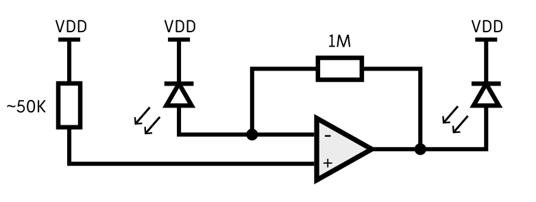
The non-inverting input is wired to the reset pin, with its internal pullup of about 50K keeping it at VDD. The input is presumed to draw no current. Both the output and the inverting input have a column of eight LEDs connected, with their cathodes at VDD.
With the 1M resistor removed, its behaviour as a differential amplifier is quite confusing. One possible factor is that all of the GPIO pins have ESD protection diodes. The legs of the LEDs are held at VDD via the GPIO output FETs, but if current is generated it would leak back to the actual VDD rail via the diodes. It's possible this leakage is the source of our signal. The bandgap of the ESD diodes will be smaller than the LEDs. The op-amp itself is also powered from VDD, and the output can reach to within a few millivolts of the rails.
Every GPIO pin has ESD diodes, which is a lot of diodes, and I tried sketching out which ones might be forming the relevant current paths, but I couldn't come up with anything that fully explained what's going on. I'm convinced that there are more than two columns of LEDs affecting the output, so maybe it's something like this:
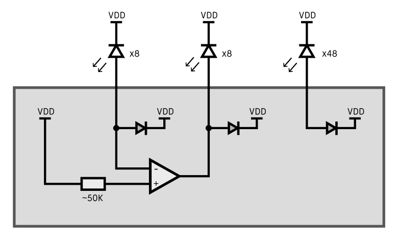
The problem with the above, if that is what's going on, is that it doesn't explain why the output is so well balanced. When the matrix is evenly illuminated, the output smoothly hovers around the 50% mark.
Various assumptions we have about ideal op-amps no longer apply; the inputs most likely do draw some current. The "50K" pullup is unlikely to be a real resistor, but a transistor mirroring a reference current, which may behave oddly if the supply is fluctuating. I think the most useful thing to do would be to try this on various batches of CH32V003 chips to see what the variation is between them. Unfortunately, right now I've only got one badge left as I've given the others away. I shall have to make some more.
To the badge
Somewhat daunted by the task of writing a full bootloader with error correction using the differential optical protocol, after writing the above text I got distracted.
Four months later and I remembered that I never actually ported the code onto the real badge. The only feature we actually need to show it off is to change the text that scrolls. That can be stored in RAM, which on the badge is battery-backed so it will persist through "off" mode until the battery is taken out. I hastily mashed the opamp code into the badge repo and delcared a no_init text buffer. The reset pin was configured as GPIO, and interrupts and events were used to recreate the old mode-switching behaviour, along with a long-press to enable programming mode.
This was then flashed onto the badge using the tiny exposed SWD pin, possibly for the last time.
I was somewhat apprehensive, because I don't fully understand the effect, so it's possible that running the code on a different board would simply not work, but to my relief it seems to work brilliantly. I'm even tempted to turn up the data rate a bit, though with a buffer of only up to 128 characters it's not like the slow bitrate is a problem.
Here's a video of it in action:
One huge improvement would be to swap out the plain UART with some type of polarity-agnostic line coding. Manchester encoding only cares about transitions, not absolute levels. The reason I say this is that programming the badge will only work in one orientation. If you rotate the badge 180 degrees, it just produces a bunch of frame errors.
Moving forwards, it would be cool to have the regular modes periodically check for a signal, so it could enter programming mode without needing a button press. That would allow the matrix earrings to be updated this way too.
The next step, if we wanted to take it, is write the proper bootloader enabling updates of the whole flash memory.
I also think there's scope for some kind of badge game, if a bunch of people had them at an event. The badges could talk to one another when faced directly at each other, so perhaps you could go around an event and collect as many tokens from other badges as possible.
Anyway, this page is now far longer than I anticipated. The changes to the badge code were pushed to a new branch called programmable and need the reset pin to be reconfigured as GPIO. The transmit program is in there too, but can also be found here.