
Flirting with the K40
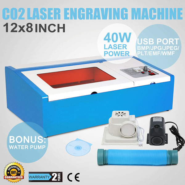
13 Feb 2016It's not often that I make impulsive purchases. But an impulsive purchase is what I made when I found out you can get a 40W laser cutter on ebay for less than £350 (the prices fluctuate – sometimes as low as £290).
Given that 40W laser cutters normally cost many thousands, even tens of thousands, you have to ask just how this one can be sold for so cheap, and indeed, if it even works. I can summarise my experiences to answer that question as follows:
- Yes, you can get a laser cutter this cheap, and yes, it works.
- It's a faff to align the optics, but nowhere near as difficult as my experience with other lasers has been
- The control software is terrible, but predictably terrible, which means it's fine once you learn its quirks
Here's a listing very similar to the one I bought:
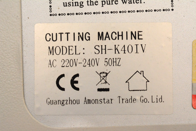
Several suppliers seem to be selling the same one or variations of it. Here's the closest thing it has to a company name:
There's lots of information about this on the web, some of which is conflicting. Least accurate of the descriptions was that of the software, but mine did come with "Moshidraw 2015" so perhaps they have updated it. It isn't nearly as bad as (apparently) some of the earlier versions were. More on that later.
The Arrival
Postage came from the UK so no import duty and only three days of waiting. It was packed in polystyrene, wrapped in cardboard, wrapped in more padding, then wrapped in a plywood crate. The laser tube and critical parts were all in copious amounts of bubble wrap. However, despite all this, it had been badly damaged in transport.The photo below is of the front of the laser tube. At the right the coolant ring has detached from the front mirror – no big deal, I can reattach it – but just to the left of the cable tie is a crack in the glass. The laser is made of three coaxial glass tubes (the middle layer is filled with the coolant) and the crack is on the inner tube, just surrounding the metal electrode.
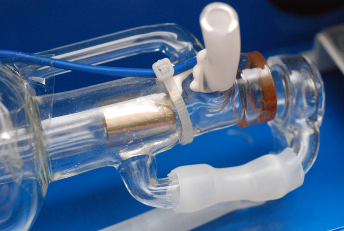
I messaged the seller and he asked me to try it anyway. Big surprise, it didn't work, and pressing the test button caused some pretty big electrical arcs from the back electrode to the chassis. After telling him this a new laser tube was posted. As for the old tube, I hung it on the wall. Water has gotten into the wrong compartments and will likely never escape. Additionally, a tiny stream of bubbles coming from the crack continued for well over a week after its arrival. If they'd stopped within a few minutes of unpacking, I'd have known the damage was recent, but as it is, we have no idea.
The new tube came from China, so I had to pay import duty (which the seller eventually refunded) and installing it was fairly uneventful, but I took an extreme amount of care over it for obvious reasons. The new tube arrived in tens of metres of bubblewrap which may not have been environmentally friendly, but I think it was justified given the circumstances. Fitting it involved soldering the wires in place and dribbling silicone sealant over it. The new tube was a slightly different diameter to the old one, which may explain why the alignment was so far off when I came to fire it up.
First firing
The smell! Oh boy, I'd forgotten it, it's been years since I've done any laser cutting. That first vaporization of a piece of paper brought back some olfactory memories.
There's a red Test button on the panel, which just fires the laser as it's held. No interlocks or anything - but these would be easy to add if I was bothered about it. The method to align the mirrors is to place a piece of paper, masking tape or post-it note over them, and see where the burn mark appears. The aim is to have the beam pass through the same point on each mirror no matter where the head is positioned. But amazingly, even before I'd begun adjusting, with the beam shifting laterally by about a centimetre over the range of the bed, it was perfectly usable. I imagine large shapes probably had a skew to them, but for something small we don't care.
It has become traditional, that when I buy an expensive new tool, one of the first things I make is a pair of earrings. How small and detailed can we go?
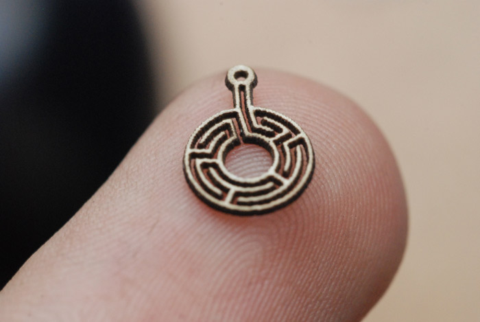
Remember—this is before I'd even aligned the optics or set the focus. Impressive! The material was some thin card from a pizza box. The design was done as a bitmap and etched. The first attempt, following the outline, was less successful as the software does not take account of the kerf (width of the cut). The outline function does work pretty well, actually, but for something as small as this it's easiest just to burn the waste away completely, rather than cut it out.
The best bit about lasers, compared to any other type of CNC, is that there is zero cutting force involved. This means that no matter how flimsy your X/Y axes are, there is never, ever any tool deflection.
Hmm, how about some acrylic? Yep, that also has its own characteristic laser-cut smell.
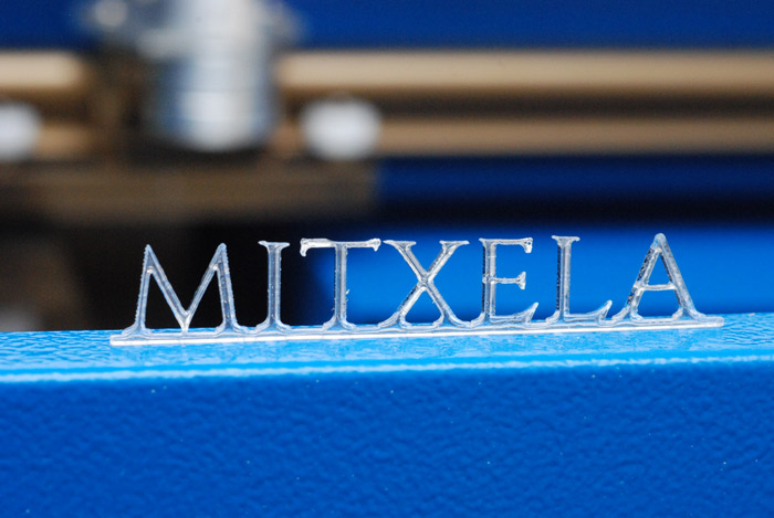
10mm high, on 3mm acrylic sheet - it seems the serifs were a bit ambitious, and they melted in places. However, that bottom edge, the long straight cut, is absolutely beautiful. You couldn't get a better finish if you polished it. Very nice.
More setup
With the first tests out of my system, it was time to actually align the optics and install the laser in its semi-permanent position. I upgraded the water-cooling of the tube from "bucket with a hose in it" to "bucket with a hose in it, with lid". And the fume extraction system? What a joke that fan was that came with it. Amazingly, the vanes of the impeller point the wrong direction in relation to the exhaust position - at first I thought it was just spinning in the wrong direction and rewrired it, but no, the vanes still point the wrong way compared to the exit position. The only way to fix the problem would be to flip the impeller over, but there's no way of mounting it... I stopped worrying about it, chose the direction which felt like it was moving the most air, and left it.Anyway, most of the suction is lost because of the stupid way the fan is mounted on the back. Just a small slot comes from the bed, and the fan has a circular inlet which doesn't line up at all and is hugely leaky. And with the fan in place you can't open the laser compartment because it's in the way. I decided to build a duct - guess what I used to do so - duct tape!
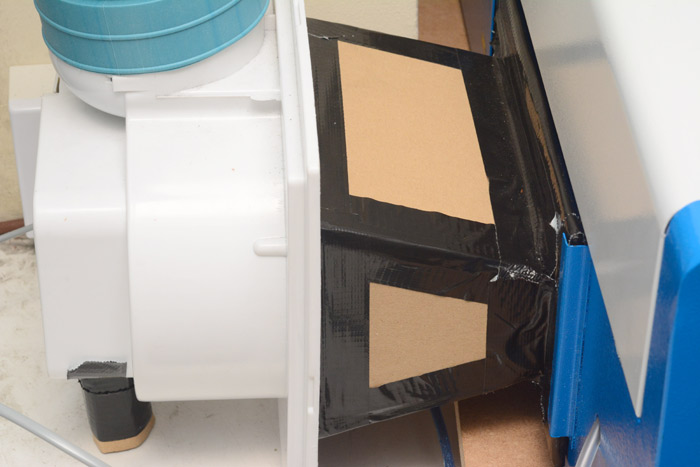
This simple cardboard trapesium is taped to the fan, but not taped to the laser cutter, it just slots into the same mountings as before. Flaps of tape keep leakage to a minimum, and the whole thing does not get in the way of the laser compartment cover (that's the white bit). The short stump of cardboard/tape on the left is an extra leg which supports the fan, as it stands on the window sill, the rest of the laser being on the desk in front of the window.
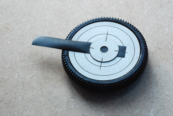
I nearly built an interlock so the machine won't work without the water coolant pump running, but never got round to it. I did build a primitive flow indicator though. It's a trimmed propeller blade from a nano-quadcopter (the CX-10) threaded onto knotted fishing wire held inside the barrel from a syringe. It's spinning in this picture, but the flash has frozen the motion.
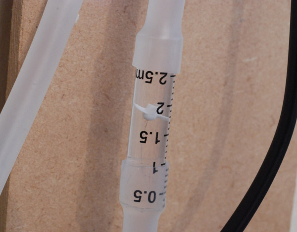
(Update: after a while it stopped working, so this design probably isn't worth copying.)
Air Assist
Many sources say you can't do without one. Certainly some of the cardboard I was cutting kept catching fire, and air assist helps suppress this.In essence an air assist nozzle blows air at the cut in order to clear the fumes. As simple as this sounds, those fumes absorb a lot of light, so even the tiniest bit of air flow can give a big boost to cutting power. It also stops plastic vapour from re-settling on the part you're cutting, which often ruins the surface finish around the cut.
You can buy the nozzles, even kits intended for this exact machine, but that's not my style. A chance to use my lathe I think!
I grabbed an aluminium rod from my box of printer bits and started turning. I drilled and tapped a hole for a threaded bit of steel to act as a spigot for some silicone tubing I had.
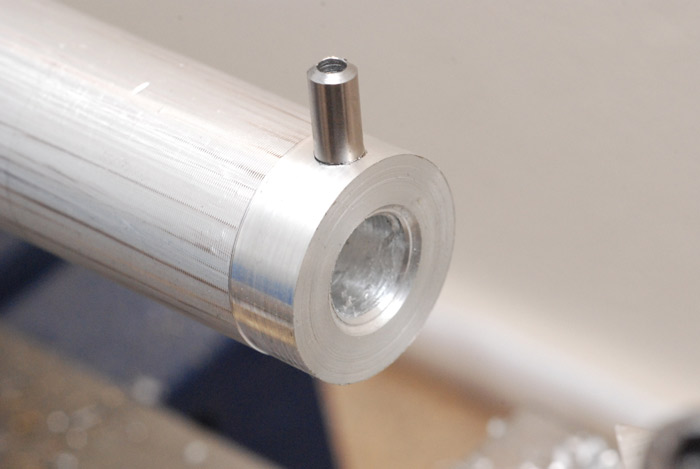
I step-drilled the main bore with progressively smaller drillbits to approximately hollow it out, and then finally, the big taper...
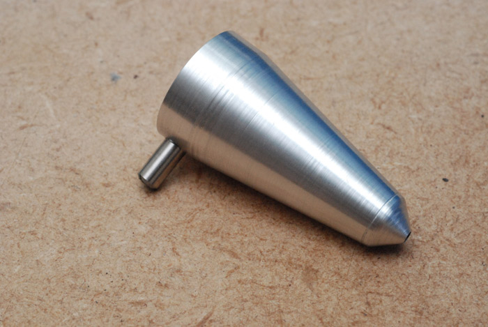
Lovely. Unfortunately the aluminium rod I used was slightly thinner than what was needed to duplicate the thread of the lens holder, so I had to come up with another way of attaching it.
Also, I soon found out that adding an air assist nozzle means you need to be much stricter with your alignment. And the longer the nozzle, and the smaller the hole at the end, the more precise it needs to be. Since I don't have a compressor, and would be using a cheap aquarium air pump for my air assisting, I had made the nozzle as long and as narrow as possible to get the most out of it.
The real problem is that unlike the first two mirrors, there is no way of adjusting the third mirror. I actually found it was massively far out – about 10° away from perpendicular – and the only way to adjust is to remove the mirror, place shims between the mirror and the mount, tighten it down, fire a test shot to check, then repeat.
So I spent a good afternoon getting the optics really well aligned, possibly even better than was needed. I would recommend using an actual 5.5mm spanner for the locking nuts on the first two mirrors, as you approach alignment it becomes waaaay too fiddly for pliers. Part of the problem is what you're locking it down to is just a flimsy bit of sheet metal.
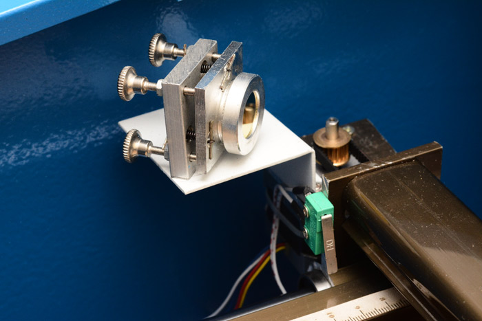
When it came to mount the actual nozzle, I used superglue. It sticks very lightly to aluminium, so it's almost temporary, but at the same time I can position it exactly where it needs to go, and quickly. Will the superglue out-gas and fog the optics? Maybe. Maybe not. We shall see how it goes.
The hose is cable tied to the moving rail and flops around as the head moves. Some people have those chain-link routing things for hoses and cables, but meh. The only time it's an issue is if you have some very light material and it's not stuck down, then in some positions the hose can brush against it and move it. Masking tape solves all problems though.
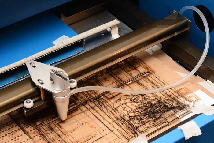
The hose currently goes out through an existing hole in the case and connects to this magnificently pathetic air pump.
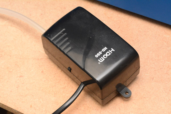
Might upgrade later. But even this is enough to substantially improve cutting.
The bed
I don't quite understand why they did this. The X/Y axes have a range of more than 20cm by 30cm, yet they fitted a type of clamp which is less than half that size. I ripped that out almost straight away. I forgot to get a picture of it, but here's a stock image from one of the listings on eBay:
Then there's the blue metal tube that leads to the extractor fan, which stupidly protrudes about 5cm into the cutting area. This is sheet steel, and is welded to the main case so there's no chance of removing it to cut it properly. Instead I used tin snips to remove the most offending part of it, leaving a very jagged edge, but at least we can finally fit a piece of A4 material onto the bed now. Phew.
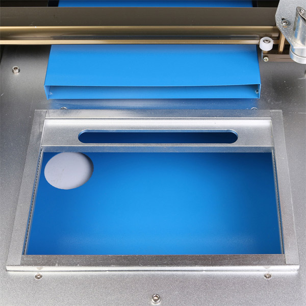
I was actually planning to give this machine a Z axis / focusing mechanism, but after a few weeks' use I decided it wasn't needed. The fact is everything I'm cutting is reasonably thin, rarely more than a centimetre. With the clamp removed, the supporting metal is about 15mm below the focus point of the beam, so simply stacking a couple of sheets of cardboard underneath the workpiece gives plenty of control over focus. The actual point of maximum focus covers a range of about 5mm vertically, so it's really not that critical.
You can see the bit of cardboard I was using to get the last few cuts in focus - it's shredded but still good for a while yet. You can also see the jagged edge of the extraction tube, which considering how awkward it is to get the tin snips anywhere near it, is actually not that bad.
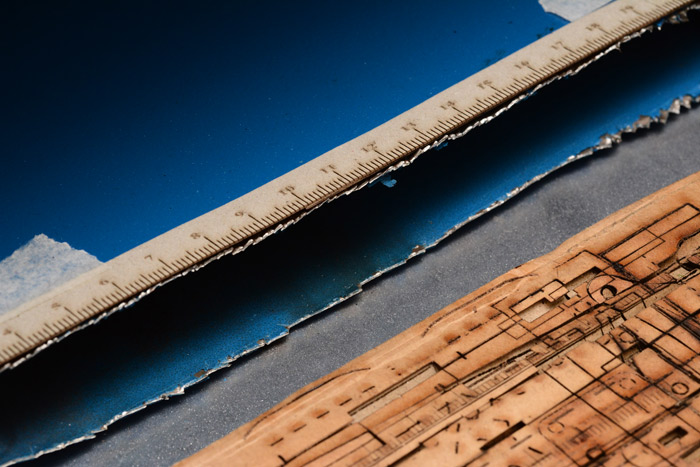
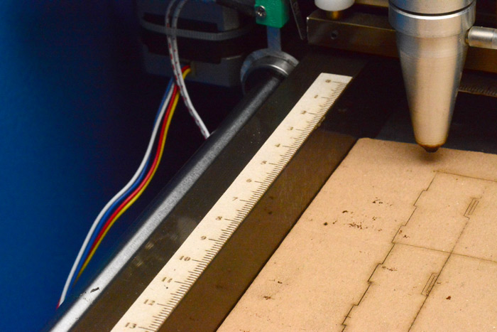
You can also see an idea which I was quite pleased with. Using the laser itself, I etched a couple of rulers and glued them just outside the cutting area. This makes it much easier when you're aligning a part for cutting to get a quick idea of what coordinates to type in. Don't expect it to be too accurate though - the startup procedure, which pushes both axes to their zero limit switches to find the origin, has awful repeatability, varying by nearly a centimetre between power cycles.
Talking of limit switches, there aren't any at the other ends of the rails - so if you type in 500mm as a coordinate, the machine will try to go there and start pulling itself apart. This is something that I really do want to do something about, at least if I keep moshidraw, because on more than one occasion it's gotten confused and tried to go to infinity. This usually happens (I think) when a line has the exact same start and end coordinates, usually as a result of asking it to outline an image that's higher resolution than what it can cope with. I cringe at that sound of the head crashing – some kind of interlock would provide a less stressful user experience.
Software & driver board - Moshidraw 2015
So many aspects of this make me laugh. I mean, just to give you an idea, the software comes with a USB stick that isn't a storage device, it's a hardware encryption key, matched to the driver board in the machine. Why would they want to encrypt it? According to one source, it's because the software itself is made of stolen components, and Moshidraw don't want others to find out. Ha!By far the biggest problem with Moshidraw is the internal conversion of units/grid resolution. The effect is that if you drag and drop something, all of the coordinates of its components will get quantized, meaning it will usually change size by about 0.1mm. Pathetic really, but to be honest for anything that requires precision I would type in all the coordinates anyway.
Something that I didn't notice straight away: if you select a bunch of shapes, then click Output to Machine, it will send them in the order they were selected. Sounds sensible, but the select tool has a marvellous quirk. If you draw a box around your objects starting from the top right corner, it will select them in a different order than if you drew the box from the top left corner. Or any other corner. This caused some havok in trying to get lines to print in correct order, and the only reliable way to do that is to highlight what you want to print by clicking the group name in the object list, in which case, it will print from the bottom of the list upwards.
Or you can go with Moshidraw's RouteOptimize option. This is a bit like selecting "random". Actually, it doesn't do too badly on shapes that were created by tracing the outline of an image. I think most of the problem is that when it tries to work out if one cut is inside another, due to the internal grid problems many of the connected lines no longer appear joined in the eyes of the algorithm.
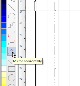
You can colour your shapes and lines. This has no effect on anything though. You can also style them to be dashed or patterned, but this absolutely does not mean they will print as a dotted line. The only way I've been able to do dotted lines is by copying and then doing a multiple paste, or as Moshidraw puts it, "PastList". Talking of translation errors, here's a funny one.
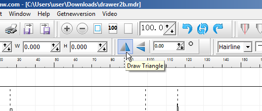
Hmm, draw triangle you say? but it seems to just be flipping it back and forth!
Ah.
Once you get used to the quirks Moshidraw really is good enough for moist porpoises. One last complaint is that although it claims to support them, I've been totally unable to get it to open DXF files. Luckily its own .mdr files are extremely simple, and I was able to write a very quick SVG-to-moshidraw conversion program. It only pays attention to SVG paths - in fact only straight lines and beziers. I plan to add more to it whenever I next convert something that has more than straight lines and beziers. Inkscape is able to take most shapes, like text, and convert it to paths. Make sure you ungroup it first.
If you find this useful please email me and it might motivate me to add the other SVG path types.
The Cutting Continues
I started googling for interesting things to laser cut. Everyone loves a dodecahedron, right?
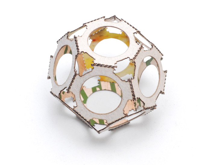
This was printed from a screenshot on some website and since I didn't modify it to match the material thickness (and printed it much smaller) the box joints were too loose and needed gluing. So I drew a few box joints myself and played with the dimensions until it was a nice snug fit with the thin card I was using. Then I made a box.
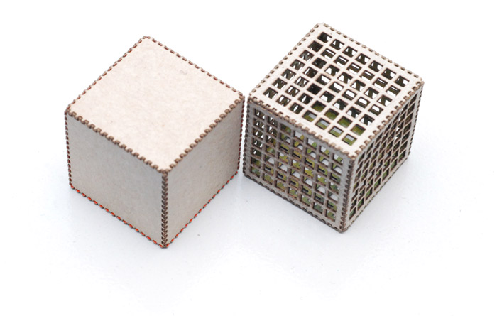
Goes together with no glue, but each of those tongues is half a millimetre wide, so it's quite fiddly to assemble. The one on the right has squares cut out, for visual interest.
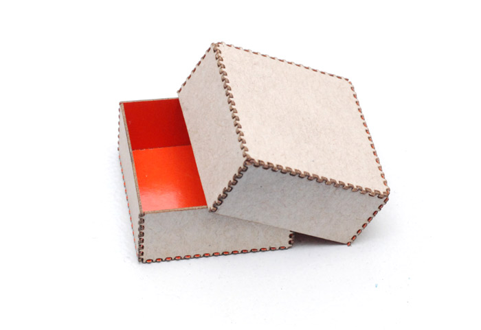
Also I copied half of one, and resized it by 5% to make a box with a lid.
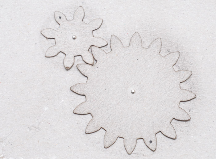
Attempted some cardboard gears. They work, but the teeth wear down pretty quickly.
I saw this iris design which I thought would be cool.
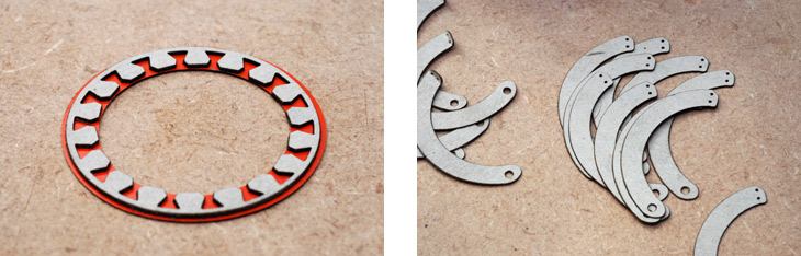
Cutting was quick but assembly was slooow.
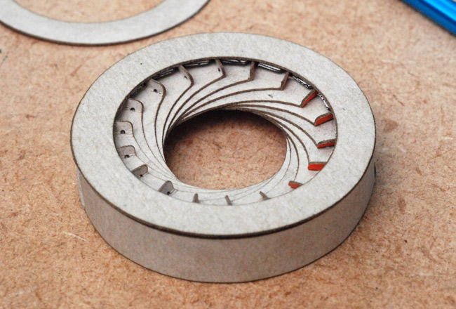
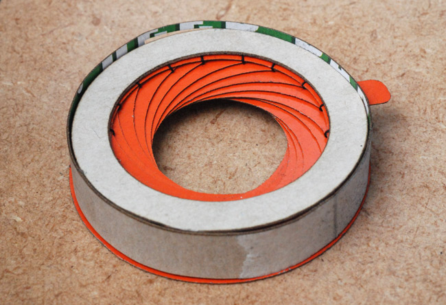
It has a tendency to fall apart when you adjust it.
Etching
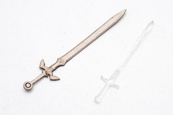
The software has no control over the laser power as far as I can make out - that's only controlled by the knob on the cover, with numbers drawn on in pen, probably by the hand of a child-labourer. So in order to etch, you need a monochrome bitmap file. I found the best results were to take a grayscale picture and resize it to be several times bigger before thresholding/dithering.Here are two swords that didn't work. (The swords that did work, I've already given away, forgot to take pictures.) The left one was a victim of Moshidraw's Route Optimize, and it seems to have cut through the handle for no reason. The right one was simply too thin for the acrylic and it melted.
It would be nice to know the exact resolution of the machine. Above a certain pixels/inch density it suddenly jumps to an aliased etch, but I haven't quite worked out where the jump is.
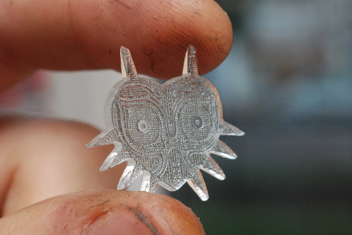
I've not yet worked out how to get a good etch on acrylic, as turning the power up often re-melts the surface to be smooth again. This is about as good as I've gotten:
while that exact same print, same settings and everything, on card comes out like this:
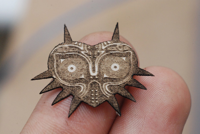
This plywood responds strangely to etching. Rather than charring, it just seems to disappear, so you end up with a sort of depth map.
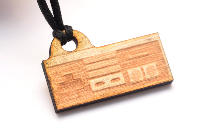
I need to order more rings. When I first got this I made lots of keyrings as gifts (mostly zelda/nintendo related) and as you can see, by the time I got to this one I was reduced to using string. String!
Component Boxes
I have, now, more than 64 little drawers for electronic components on my shelf. Would you believe that the first 32 were made by hand, with a stanley knife and glue?
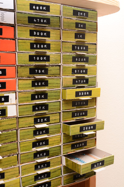
They were designed to be just slightly wider than the paper strips that resistors are stuck to. The design was based on the shape of a matchbox, just a bit bigger. They work magnificently, not only are they a more useful shape than the commercially available options, they're also substantially cheaper (free). I even started stockpiling old card, specifically in case I needed more boxes. And it turns out one always needs more boxes. The design was ripe for laser cutting, and while we're at it, avoiding any glue too.
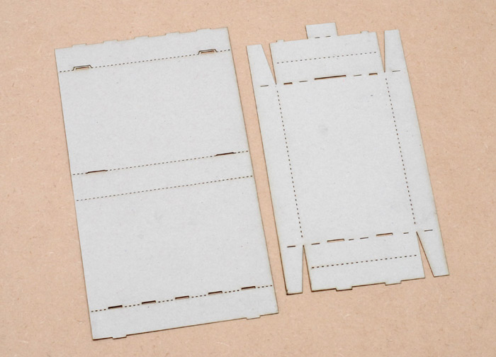
The drawer itself it pretty simple, tabs go into slots and it stays together. Handle sticks out the front. The outer part is not so satisfying. What I eventually went with is a bunch of tabs that are slightly wider than the slots so they jam, and then the flappy outer bit is just retained with two loops. This could be improved, but it holds sufficiently well, and while they're stacked on the shelf there's no forces on it anyway.
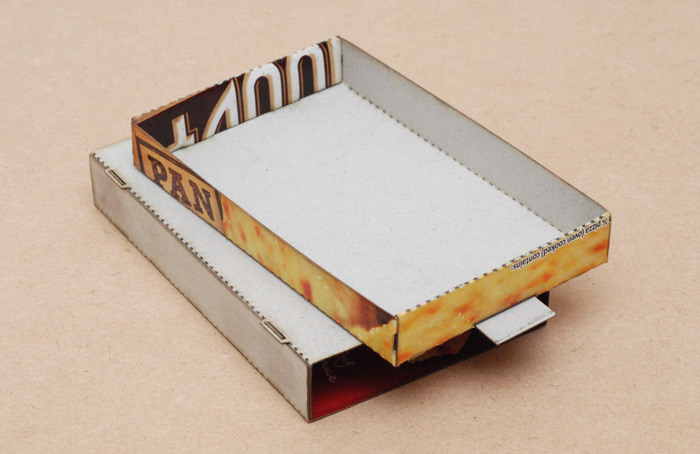
What an excellent use of a frozen pizza box.
Pinhole Camera
Pinhole cameras are often advertised as having laser-cut pinholes. I suppose that makes them laserhole cameras.I took a strip of electrical tape, washed away the glue with kerosene, then tried to make a series of progressively larger holes.
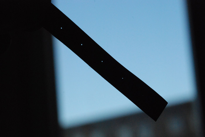
This was done by just doubling the amount of time the laser is on for each hole, and as you can see there's a very nonlinear relationship between laser time and hole diameter. The smallest one is almost invisible, the largest two look the same size. But there's plenty of time to refine this.
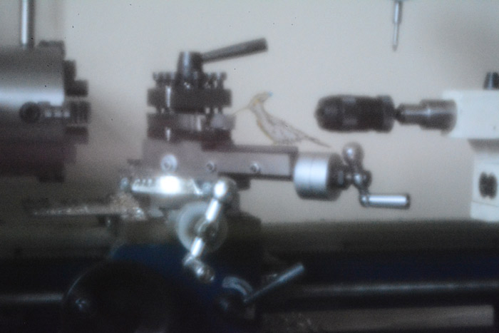
Rather than build a camera, I took an old body-cap for a digital SLR, hollowed it out, and made a laser-cut mount for the pinhole strip.
The top ring is glued to the lower ring in two places so the pinhole strip can slide through. Variable aperture!
I haven't shot anything interesting with it yet, but here's a picture of my lathe taken through the pinhole. There's a laser cut bird sitting on the compound slide.
T-shirt printing
I wanted to try a little experiment. Here's some fabric paint, it sets by being ironed on.
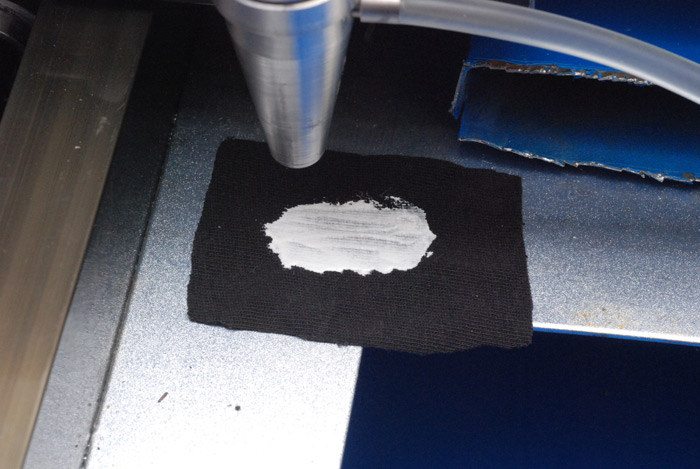
So I etched a pattern, and washed away the excess.
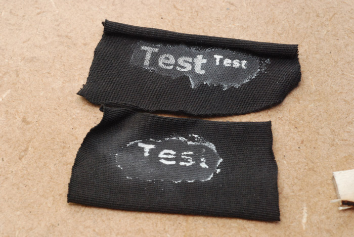
Well, it sorta worked. Possibly with refinement it could be a viable technique, but the main problem is it's very wasteful of the relatively expensive paint. Also it evidently needs washing again to remove the unetched paint completely (I had thought that simply leaving it to dry would not bond it to the fabric, but perhaps not?).
The more reliable, tried and trusted method to print T-shirts with a laser cutter is by stencilling. And moshidraw is actually perfectly good at tracing the outlines of monochrome bitmaps.
Just to get my hand back in the game, I decided to bleach spray this simple Laputa-inspired design. Production (touching up the image in photoshop, laser cutting and the actual spraying) totalled about half an hour.
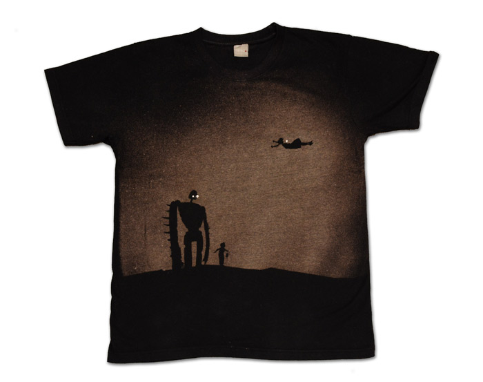
I was hoping for the spray to clump together more, leaving a spotty texture that would look like stars. Anyway, more ambitious designs will come later.
On the Subject of Robots...
Aside. When I was seven years old I found an astounding book. It was hidden, crumbling and forgotten in the school 'library'. The book's title was "How to Make Computer Controlled Robots" and thanks to the internet I can even show you its cover:

That library (one bookcase) later disappeared to become a computing suite (three computers) but not before I had photocopied the actual plans from the back of the book, to build the robot arm from balsa wood and veroboard.
In retrospect I think I got reasonably far with the project, all things considered, but no, I never finished it. And unfinished projects, no matter how long ago, do tend to niggle at the back of one's mind. Consider my feelings, then, when I saw the design of a laser cut robot arm on instructables. It was called the MeArm. It's cut from a single sheet of 3mm A4. It uses those 9g servos that - yes - I have a whole bag of in my drawer.
I chucked the vector file through my svg-to-moshidraw converter, loaded a sheet of plywood, and started blasting my way through it. Later that same day, I had myself a robot arm!
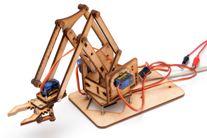
Cut a few corners since I didn't have the right bolts but it's perfectly functional. I also added strips from a rubber band to the jaws to give it better grip. Marvellous.
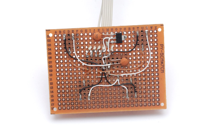
It would make sense for the remote to have direct control of the motors, but rather than damage them by pulling their control circuits out I chucked together a very simple PWM driver for them using an Atmel something-or-other.
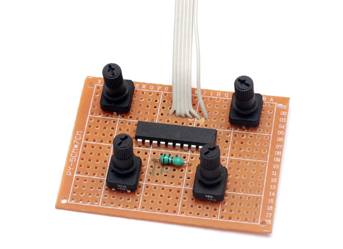
Each pot directly controls the position of one servo.
In conclusion
Laser cutter. For £325.All in all, pretty good bang for one's buck, I do say, quite so, indeed!
Update
It's 2025, and I think this page deserves an update.Buying a cheap laser cutter is one of the best decisions I ever made. In the ten years since I bought it, it's seen thousands of hours of use. I've come to completely depend on it: it's at the heart of most of my prototyping, it's formed the backbone of dozens of projects, it's led me to paid work and it's churned out almost a thousand precision clock kits.
Some notable projects that couldn't have happened without it are the MIDI musicbox, the Execu-Calm, and the MIDI slide whistle (and its successor).
What's astonishing is how reliable it's been, after that initial period of setup I've just not had to worry about it. A few years ago I moved house, which involved putting the laser cutter into storage for a few weeks, and then installing it again in the new place. I had worried about whether it would survive the journey at all, as I disconnected the coolant tubes and gently settled it in the boot of my car, but not only did it survive, I didn't even need to adjust the optics! It resumed its duties without batting an eyelid.
I never did upgrade the control board, though I always planned to. Moshidraw is dreadful, but it still works. One of my only regrets is that I invested in the K40 too early – newer models can be augmented by better software like K40Whisperer, but mine is too old to be supported.
About the only upgrade I've actually done since this page was first written is to get a better air pump. A beefier pump was well worth it, and lets us cut faster than before.
In late 2024, as we reached nine years of continuous use, I finally hit a problem. The tube current progressively sagged, despite the power level, and eventually hit zero. My interpretation was that the tube had finally gone.
I can't cope without a laser, so I ordered a replacement tube almost immediately. No time to shop around, I grabbed a 40W CO2 tube for £156. Changing the tube is a whole ordeal, as described above. It also means we need to re-align the optics. But after installing the tube, still no luck! Turns out it wasn't the tube that had gone at all, it was the high voltage power supply.
Oh how I kicked myself for not testing more thoroughly! I'd removed the tube and ruined the optical alignment for no reason.
I ordered a new laser power supply, one which was supposed to be a drop-in replacement. While it did drop in, when I pressed the "test" button it partially destroyed itself. After a very tedious debugging session, I found that the original K40 had been wired up incorrectly. The "laser on" signal had been wired directly to the test button, for some reason, and while the new power supply had the same signal connections, the test button was apparently implemented differently.
I re-wired the machine so that the signal from moshidraw triggers it correctly. I dismantled the power supply and replaced the blown diodes and resistor. I finally got the machine working again, phew!
The beam quality seemed somewhat worse, it didn't seem to focus to a good point, but it was good enough for cutting.
Just three months later, and the machine was dead again. In fact, it was precisely three months and four days after I'd bought the new tube. This time, it really was the tube that had gone. The tube had a three month warranty.
At this point I began to wonder if the laser's days were over. I depend on it so much, I could easily justify buying a new one. But I dilly-dallied. A friend suggested I should buy yet another tube, from the same company, and then send the previous one back under the new tube's warranty. Devious, but I'm not that kind of person.
Instead, since there was nothing to lose but my time, I re-installed the nine-year-old tube back into the machine. This was even more effort than it should have been, as I'd cut the cables right at the solder joints since I'd believed it to be dead.
It worked. Astonishingly, like magic, I didn't even need to align the optics this time. I somehow got lucky, incredibly lucky – it went together again, and started working flawlessly. Three months later, it shows every sign of lasting another ten years.
I love my K40.
The ordeal did get me thinking about what I would buy today, as the world of home laser cutters has changed a lot. The niche of the K40 has largely been displaced by diode lasers. The 10W ones can cut plywood almost as fast as a CO2, and you've not got any mirrors to worry about, and the cooling is trivial. You get almost as much performance for a lot less faff, and a lot less money. The only disadvantage is that you can't cut clear acrylic, as the visible light beam goes right through it.
Another product now available, just a bit more expensive, is a fibre laser. For just £1500, you can get a 20W output fibre laser with galvos and a rotary axis. The appeal is that they can etch metal. Gosh it's tempting. The downside is that it can't really do any of the things I use my laser for, such as cutting plywood and acrylic. If I got one, it would be in addition to the K40. Maybe one day!