
kiloboot: 1kB TFTP Bootloader for AVR / ENC28J60
2 Jan 2017Progress: Complete
- This is quite a long page, feel free to skip ahead to the video, and instructions on how to use the bootloader.
I hate using things I don't understand.
To understand something, really, you have to build it. That's what I was thinking when I tried to build a sewing machine out of old printers. And I stand by it! The only way I really got to grips with UART, SPI, I2C and so on was by bit-banging them.
The internet. Having built many websites and online games, I'm pretty sure I understand how the higher-level protocols of the internet work. But the lowest I've ever had to program with is sockets – opening a raw UDP or TCP data stream. TCP, especially, is a mysterious protocol that can deliver a continuous stream of bytes, guaranteed, without you having to ever understand it.
So. It is time to understand the internet.
I think there's no single aspect of the internet that's especially complicated, the scary part is just the number of acronyms. There must be hundreds of them for all the different bits of the dozens and dozens of protocols. Since explaining things is often a good way to spot holes in your own knowledge, I'll start by trying to summarize the TCP/IP stack.
Layers
The protocols that make up the internet are split up into them. The combination of all these layers forms a stack.
PHY & data link
The lowest layer in the stack is the physical layer, or PHY. This is the actual method of transferring zeros and ones from one device to the next. In the case of the ethernet port on my laptop, this is a cat5 cable with twisted copper wires carrying a manchester-encoded differential signal. Other physical interfaces include 2.4GHz wireless (for wifi) and fibre-optic links. Physical layer. Simple.The second-lowest layer in the stack is the Data Link (or "network") layer. In the case of ethernet, this is the ethernet packet format. The distinction is that 10Mbit, 100Mbit and Gigabit ethernet all use the same data link layer, but have different physical layers.
All devices with an ethernet (or wifi) interface have a hard-coded MAC address. This 48-bit number is programmed into the chip at the factory, and is supposed to be unique in the world. Every ethernet message has a "Source" and a "Destination" MAC address in its header.
Rambling aside: The name "ethernet" doesn't really make sense any more. The old style of ethernet used a coaxial cable for its physical layer. All the computers in a network would be wired to this same bit of coaxial cable, and if any one of them sent a signal onto the coax, all the others would receive it. The cable was like a virtual "ether" that signals would traverse. You can immediately see the problem with this set-up: what if two devices wanted to talk at once? They had to wait until the line was clear, and then start sending in the hope that no-one else would interrupt. If two messages collided, the rule was to stop transmitting, and wait a random amount of time before starting again.
Each device that hears the message would look at the destination address, and if it wasn't its own MAC address, it would throw the packet away. Nowadays when you use ethernet, you're almost certainly plugging your computer into a network switch via a full duplex line, so collisions are impossible. The switch does the job of looking at where messages are headed, and sending them there.
An ethernet frame looks like this:
+-----------------+-----------------+---------+------------------------------+---------+
| destination MAC |    source MAC   |EtherType|        Data Payload          |   CRC   |
|     6 bytes     |     6 bytes     | 2 bytes |      (up to 1500 bytes)      | 4 bytes |
+-----------------+-----------------+---------+------------------------------+---------+
A header, and the CRC at the end is the footer – this provides your basic error checking. By putting it at the end you can calculate it as it happens, without having to hold the whole message in memory. One of the nice things about internetworking is that it's unreliable by design. This is quite liberating. If a frame comes in with an incorrect CRC, indicating the data is corrupted, just throw the frame away. It's up to the higher-layer protocols to worry about retransmission.
The EtherType field identifies what the message contains. For instance, IPv4 messages have the code 0x0800. The payload can be up to 1500 bytes. The end of the frame is signalled by the physical layer's end-of-frame sequence. Basically, the ethernet frame format is like an envelope, with addresses on the outside, and a payload that could be anything. The idea of the layer stack is that the payload of the ethernet frame can be a higher-layer protocol, itself with a header and addresses and a data payload, which may again be higher protocol with its own headers, and so on.
The IP layer
Within the protocol stack, the data link and physical layers stand out a bit, because as you send a message over the internet, it may go through many different types of data-link layers. Each hop across the internet will have different MAC addresses.Networks are built with a technology like ethernet. Multiple networks are connected together, into an internetwork, using the Internet Protocol. IP messages have addresses, which are called, yep, IP addresses. Traditionally (by which I mean, without NAT – Network Address Translation) every device on the internet would have a unique IP. A company would buy a block of IP addresses for their network, and in doing so, draw an imaginary line down the IP address. The block might be something like, 123.45.67.0 to 123.45.67.255, in which case the line would be at the third dot. Originally blocks were only broken up by bytes, they were called Class A, Class B and Class C networks. Then people realized that that was silly, and invented subnet masks. This just means placing your imaginary line at any of the 32 bits of an IP address, and making a mask where all of the bits to the left of the line are one. So, by doing a logical AND between the subnet mask and the IP address, you can tell if it's on the current subnet, or outside, on a different subnet of the internet.
You want to send a message to a different IP address. If the subnet mask says it's on the local network, you can fill in the hardware (MAC) address for the target and send it there directly. Otherwise, you send the message to a "gateway" router, which passes it on, out into the wilderness of the internet.
An IPv4 header looks like this:
    0                   1                   2                   3
    0 1 2 3 4 5 6 7 8 9 0 1 2 3 4 5 6 7 8 9 0 1 2 3 4 5 6 7 8 9 0 1
   +-+-+-+-+-+-+-+-+-+-+-+-+-+-+-+-+-+-+-+-+-+-+-+-+-+-+-+-+-+-+-+-+
   |Version|  IHL  |Type of Service|          Total Length         |
   +-+-+-+-+-+-+-+-+-+-+-+-+-+-+-+-+-+-+-+-+-+-+-+-+-+-+-+-+-+-+-+-+
   |         Identification        |Flags|      Fragment Offset    |
   +-+-+-+-+-+-+-+-+-+-+-+-+-+-+-+-+-+-+-+-+-+-+-+-+-+-+-+-+-+-+-+-+
   |  Time to Live |    Protocol   |         Header Checksum       |
   +-+-+-+-+-+-+-+-+-+-+-+-+-+-+-+-+-+-+-+-+-+-+-+-+-+-+-+-+-+-+-+-+
   |                       Source Address                          |
   +-+-+-+-+-+-+-+-+-+-+-+-+-+-+-+-+-+-+-+-+-+-+-+-+-+-+-+-+-+-+-+-+
   |                    Destination Address                        |
   +-+-+-+-+-+-+-+-+-+-+-+-+-+-+-+-+-+-+-+-+-+-+-+-+-+-+-+-+-+-+-+-+
   |                    Options                    |    Padding    |
   +-+-+-+-+-+-+-+-+-+-+-+-+-+-+-+-+-+-+-+-+-+-+-+-+-+-+-+-+-+-+-+-+
(from RFC791)The 16-bit ID is a unique identifier, coupled with the addresses, which is mainly used to allow fragmentation. If a packet is too big for a network, it can split it into multiple packets, repeating the header and using the frag offset field and the "more fragments" flag. It's up to the receiver to piece it back together again. The different fragments may even take different routes across the internet. To be honest the routing and associated protocols are things I know very little about, since it's not something you ever encounter when writing server or client software. However I do quite like the principle behind traceroute.
One of the problems with designing packet-switching networks is trying to avoid loops. Switches and routers look at the address, work out which direction it needs to be sent, and transmit it there. A loop could be devastating, with packets incorrectly routed and ending up going around and around forever. To combat this, the IP header has a "time to live" field. Each time the packet is forwarded, this number is decremented, and if it ever reaches zero, the packet is dropped and an error message is sent to the source address.
Traceroute abuses this by repeatedly sending the packet while incrementing the TTL value. Each packet times out at a different stage of the journey, and the result is a flood of error messages which identify every single machine the packet was routed through. A map of its route across the internet. Pretty cool.
Transmission Layer
There are two main transmission-layer protocols: TCP and UDP. UDP is basically a "wrapper" for IP messages (not a good analogy, since wrappers don't normally go on the inside of envelopes). Sometimes you don't care about reliability, you want speed and simplicity and sending data at the IP layer would be good enough. UDP lets you do that by providing a tiny header that just has transmission-layer addresses (port numbers), a length, and a checksum.TCP is where the magic happens. IP messages are unreliable, by design. They might never make it to their destination, and we're not bothered about it. What's kinda cool is that by a system of acknowledgement messages, TCP can open a reliable, guaranteed connection over the unreliable underlying layers.
Every message is acknowledged, which means you send a message and wait for a response with the ACK flag set. If your message, or even the acknowledgement, is lost, then a timer expires and the data is sent again. Since most messages make it, we can measure the ordinary round-trip time and set the timeout to be just a little longer than that.
A connection is "opened" by sending synchronization (SYN) messages, which agree on a "sequence number" – basically a random number that labels the first byte of data. Then, acknowledgements can just send a single number in response which means, "I've received all of the data up to this exact byte". The ACK messages also state the number of bytes the recipient is willing to accept, called the receive window. If it's busy, it can tell the other party to stop sending data for a while. The client and server have to both keep track of:
- data sent and acknowledged
- data sent but not acknowledged
- data ready to be sent
- data not ready to be sent (beyond the recipient's receive window)
As packets are passed back and forth, these pointers to the data buffers move along and form what's called the Sliding Window. On the face of it, this system should work brilliantly, but actually there are all kinds of problems that arise, and there are many rules necessary for the system to work efficiently. Data packets can arrive out-of-order, so the option to selectively acknowledge was added, which requires two pointers. If the server is busy, it may have a very small receive window, which only increases a byte at a time. In this case we obviously need to wait a while, instead of sending packets with a single byte payload (remember the combined TCP/IP header is at least 40 bytes).
But sometimes we want to send single bytes. Telnet would be unusable if we couldn't send single keystrokes, so for that, the push flag was added. The rule is, we can send the contents of the send buffer right now (push), but only if there is no data waiting to be acknowledged.
The TCP header looks like this:
    0                   1                   2                   3
    0 1 2 3 4 5 6 7 8 9 0 1 2 3 4 5 6 7 8 9 0 1 2 3 4 5 6 7 8 9 0 1
   +-+-+-+-+-+-+-+-+-+-+-+-+-+-+-+-+-+-+-+-+-+-+-+-+-+-+-+-+-+-+-+-+
   |          Source Port          |       Destination Port        |
   +-+-+-+-+-+-+-+-+-+-+-+-+-+-+-+-+-+-+-+-+-+-+-+-+-+-+-+-+-+-+-+-+
   |                        Sequence Number                        |
   +-+-+-+-+-+-+-+-+-+-+-+-+-+-+-+-+-+-+-+-+-+-+-+-+-+-+-+-+-+-+-+-+
   |                    Acknowledgment Number                      |
   +-+-+-+-+-+-+-+-+-+-+-+-+-+-+-+-+-+-+-+-+-+-+-+-+-+-+-+-+-+-+-+-+
   |  Data |           |U|A|P|R|S|F|                               |
   | Offset| Reserved  |R|C|S|S|Y|I|            Window             |
   |       |           |G|K|H|T|N|N|                               |
   +-+-+-+-+-+-+-+-+-+-+-+-+-+-+-+-+-+-+-+-+-+-+-+-+-+-+-+-+-+-+-+-+
   |           Checksum            |         Urgent Pointer        |
   +-+-+-+-+-+-+-+-+-+-+-+-+-+-+-+-+-+-+-+-+-+-+-+-+-+-+-+-+-+-+-+-+
   |                    Options                    |    Padding    |
   +-+-+-+-+-+-+-+-+-+-+-+-+-+-+-+-+-+-+-+-+-+-+-+-+-+-+-+-+-+-+-+-+
   |                             data                              |
   +-+-+-+-+-+-+-+-+-+-+-+-+-+-+-+-+-+-+-+-+-+-+-+-+-+-+-+-+-+-+-+-+
(from RFC793)
So, are you following along? We have the network layer, with hardware (MAC) addresses; the internetwork layer, with IP addresses; and the transmission layer, with its "port number" addresses. When you communicate at the transmission layer, the combination of (source port, source IP address, destination port, destination IP address) gives you a "socket". Outgoing port numbers are generally chosen at random ("ephemeral") but servers often use the incoming port number to identify what process or protocol is requested. 80 is the default for web pages, 23 is telnet, etc.
The higher layers, we're much more familiar with. HTTP is sent as plain text, the headers are a series of names and values, then the first blank line indicates the start of the body. Since it's all using TCP and plain text, the higher layers do tend to blend together. Telnet, for instance, is just a TCP connection (that uses a few non-ascii escape characters for option negotiation). If you open a telnet connection to a webserver, and type out an HTTP request ("GET /index.html HTTP/1.1" etc) you'll receive the response. In fact the only indication of which protocol you're using is given by the port number you initially requested. Another application-layer protocol is DNS, which we use all the time, indirectly. Every time you type a URL, your operating system silently makes a DNS request to find out its IP.
There you have it, ladies and gentlemen, in just over 1500 words, the internet. But we still don't really understand it. As I mentioned before, there are dozens and dozens of protocols, and just reading about them isn't going to help. We need to start playing with them.
The Plan
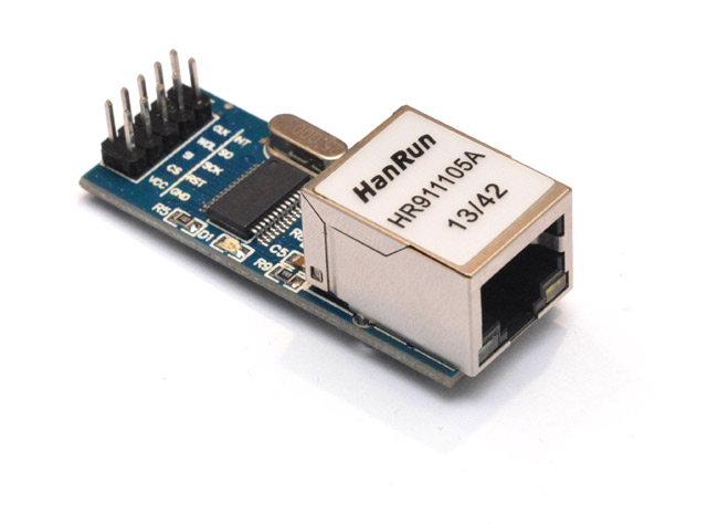
I figured I'd make something silly, like a webserver written in assembly. But how low do we go?For my experiments, I decided to play with a chip / breakout board of the ENC28J60. This seemed like a nice middle-ground in terms of where we start. It implements the PHY and gives some help with the second layer, as it has a hardware CRC calculator. The breakout board it comes with has all of the parts needed, including the jack and the magnetics/transformer. It's also cheap, at only £3 including first class postage.
There are other ethernet boards which implement more help with the higher layers, but obviously for this, we don't want that. And they're more expensive. The other thing I considered was implementing the PHY from scratch, but I feel that's an entire project in itself. I haven't actually seen the document that defines it (IEEE 802.3) but I'm assuming it won't be possible to bit-bang using an AVR, since the symbol rate is 10Mbit and our max clock frequency is 20MHz.
Everything above the data link layer is defined in the RFC documents, which are all available to view for free, because the internet is open and wonderful.
It was about the moment my ENC28J60 arrived I noticed the 1kB challenge on Hackaday. Since most of my embedded projects are written in assembly, I feel like I have a kind of duty to enter. Many of my MIDI projects are already under a kilobyte of code. I think the Midi Monotron arpeggiating MIDI-to-CV converter was about 300 bytes of code, plus a 256 byte lookup table.
As a first project with the ENC28J60 I wondered what I could make in less than a kilobyte. An internet-of-things thing which read some sensor and returned the data over UDP would be doable. But... kinda pointless. I feel it's stupid to restrict yourself to 1kB unless there is a reason, such as, that's the size of your flash memory. The ATtiny13 has 1kB of prog mem, but, why would you ever choose it over an ATtiny85 for a hobbyist project? I tried to think of something that would be more than just a demo, conforming to an arbitrary code limit. Something useful. Then it occured to me – an ethernet bootloader.
If you're not familiar, a bootloader (in the context of microcontrollers) is a small program that reads data from somewhere else and writes it to the main program section.
Bootloaders are one of the few programs that you really do want to squeeze as small as possible, so as not to take up space that would be used by the application. They "hide" in the last few pages of the flash, in a bootloader section which on most AVRs is selectable in size: 256 words, 512 words, 1024 words, 2048 words or 4096 words. A word is two bytes, so it's the 512 word section we're looking at. Can we fit our protocol stack into that?
Just to scout out the competition, I looked to see if anyone else had written an ethernet bootloader with this part, and yes, there were a few, but all of them were much, much bigger than 1kB. I remember Mike Harrison of mikeselectricstuff once talked about intermediate-memory bootloaders, where you implement your protocol stack in the application, then write the received data to an external memory chip, and your actual bootloader only has to load the data from the external chip. Hmm. There was an interesting bootloader written by kehribar which uses UDP broadcast messages exclusively. This is a clever technique, which means you don't even need to give the thing an IP address, and the whole process is greatly simplified. That fits into the 4096 byte section.
The problem with that, is that you can only boot from the local network, using your proprietary protocol. I admit that in most cases, you do want to only boot from the local network, but... then you're building a network-of-things, not an internet-of-things. I arbitrarily say that my bootloader should be able to boot from anywhere in the world, using common protocols.
The protocol we want to use is TFTP, the Trivial File Transfer Protocol. This was invented specifically for network booting. It's common for the device to use this in conjunction with DHCP which can tell the device where to find its boot file, but I got a bit scared by the length of DHCP messages – well over 200 bytes, which just eats up so much of our space. This isn't actually a deal breaker, I later decided that a DHCP client probably can fit into our 1kB bootloader, but to begin with I think we should give the device a static IP. I'm also not that convinced by the DHCP/TFTP method, since I'm already running a DHCP server on my home router, but I would have to run a second one, say, on my laptop, which would serve the boot file name. And again we're limited to the local network.
All of the DHCP/TFTP bootloaders I could find were 8kB or more.
DHCP works by handing out leases for IP addresses. They say, you can have this IP address for one day (or whatever). When half of that time has elapsed the device will start asking to renew it. It's possible to configure my home router to say "the device that has MAC address X always gets IP address Y" but we needn't actually bother. The addresses are handed out from a pool, and the router settings say that my pool is from 192.168.1.64 to 192.168.1.252. So I can just give my device an address outside that range, and there will be no conflicts.
Before DHCP and BOOTP, you would have to configure IP addresses manually. And you still can do so. The device doesn't have to announce it or anything, it can just start using it and assume everything's OK.
Our initial plan is: A TFTP bootloader, which has a fixed IP address, and loads a file from an arbitrary server, on either the local network or the internet. The chip I'll be writing it for is the ATmega328P, which is very popular. I've never actually used an Arduino, but presumably by writing it for this chip the end result will be Arduino-compatible. AVRs are all pretty similar anyway, so it wouldn't be much effort to port this to a different AVR chip.
Begin
I don't know why so many breakout boards come with double-rows of header pins which can't easily be breadboarded. I suppose I ought to get some female/male jumpers. But for this development I'm using the following two homebrew adapters:
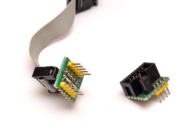
The one on the left is an IDC cable expander. There are ten header pins on the breakout board, so the ubiquitous IDC cable is used and this adapter spreads the pins into a breadboard-friendly format. The one on the right is specifically for programming AVRs over ISP. On 90% of the atmel chips I own, the SPI pins and VCC are arranged in the same order. The other two pins needed are reset and ground, for which there are female headers on the adapter. This thing lets you plug an ISP cable into a breadboard, and works with every breadboardable AVR chip I've got. The setup:
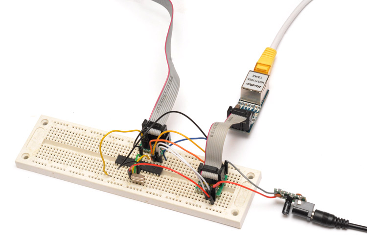
I've given it a 16MHz crystal, but there's no reason this wouldn't work with the internal oscillator. The barrel jack/regulator on the right is the power supply. It's possible to power the board over ISP, but the ENC28J60 draws a lot of current and I found that if it dropped even slightly below 3.3V it started having problems. The wiring is:
PB1 <--> INT
PB2 <--> CS
PB3 <--> MOSI
PB4 <--> MISO
PB5 <--> SCK
The INT pin is optional, but it can be configured to go low when a packet is received, which means we don't have to continuously poll the chip.
The datasheet for the ENC28J60 is pretty dense. The SPI commands are split into a 3-bit opcode and a 5-bit address, but there are more configuration registers than would fit into a 5-bit address, so they've given it four different "banks" of registers. You have to select the bank in one command, then set the register in the next. There are separate op-codes for reading and writing registers, also setting and clearing bitfields in those registers. Then there are commands to read and write to the buffer memory.
The very first thing I did was enable the SPI master and write a quick enc28j60write subroutine.
Since there's a lot of functionality we don't need, the quickest way to get an overall feel of what registers need to be set is to find someone else's driver for the chip. There's the pointers to the circular buffers; there's the packet filtering, we want to receive broadcast packets and our MAC address; there's the built-in CRC calc that we want to use; maximum packet size; and quite a few more. Since many of these registers have both high and low bytes, the total number of calls to our subroutine to initialize the chip comes out at 40.
The driver I copied all the register definitions from used a function that OR'd the register address with the opcode before sending the SPI. I don't know if the compiler would have optimized that out, but in assembly we can explicitly do this using the preprocessor macros. Avrasm2 supports both assembly macros and also the C-style macros, so with a definition like this:
#define ctrlReg(addr) ENC28J60_WRITE_CTRL_REG | (addr & 0x1F)
we can write to a control register like this:
  ldi r16, ctrlReg(MAMXFLL)
  ldi r17, low(MAX_FRAMELEN)
  rcall enc28j60write
low() being a built-in macro to grab the low byte of a number. Hmm, three instructions, so six bytes, that would make 240 bytes just for initialization. We can optimize our init code hugely without any loss of clarity by simply listing the arguments to the subroutine calls in program memory and iterating. You can write data directly to PM by using the .db directive:
.db ctrlReg(MAMXFLL), low(MAX_FRAMELEN)
.db ctrlReg(MAMXFLH),high(MAX_FRAMELEN)
etc
The iterator is just a couple of LPM Z+ instructions and the subroutine call, so our init code is now under 100 bytes. I like how labels can be used everywhere, as if they were a variable. Anything that ends in a colon is a label. We can stick a label at the end of the data, even if there's no data beyond it, called initCodeEnd. Then, when we call our iterator, the number of iterations is calculated by the preprocessor when we do (initCodeEnd-initCode). Even if we add or remove registers from this list, it won't affect it.
We could optimize further but I'd like to keep it flexible while we're developing. The next thing I did was implement a basic readPacket routine. I set the chip to use its interrupt line when a packet comes in. So we wait until that pin goes low before reading out the packet, and sending it to the UART port for debugging.
As soon as I connected the ethernet cable to my router, there were a lot of packets appearing. A big wall of hex data, but I immediately spotted a group of six 0xFF several times over. This is the broadcast MAC address, and is almost certainly an ARP request. The six bytes before the destination MAC are data from the ENC28J60, so belong to this packet.
A4 01 40 00 C0 03 FF FF FF FF FF FF A4 4E 31 3C C8 14 08 06 00 01 08 00 06 04 00 01 A4 4E 31 3C C8 14 C0 A8 01 53 00 00 00 00 00 00 C0 A8 01 45 00 00 00 00 00 00 00 00 00 00 00 00 00 00 00 00 00 00 3C 16 3B 2C
I put carriage returns and comments into the log file to make it clearer:
A4 01                 // pointer to next packet
40 00                 // packet length
C0 03                 // enc28j60's packet status vector
FF FF FF FF FF FF     // (ethernet) dest addr
A4 4E 31 3C C8 14     // (ethernet) source addr
08 06                 // EtherType = ARP
00 01                 // hardware type = ethernet
08 00                 // protocol= ipv4
06 04                 // hardware length, protocol length
00 01                 // operation = request
A4 4E 31 3C C8 14     // sender MAC
C0 A8 01 53           // sender ip
00 00 00 00 00 00     // target MAC
C0 A8 01 45           // target ip
00 00 00 00 00 00
00 00 00 00 00 00     // padding
00 00 00 00 00 00
3C 16 3B 2C           // CRC
Excellent! It's an ARP request, 192.168.1.83 is looking for 192.168.1.69. The sender's MAC address belongs to my laptop, which is interesting since it's connected to the router via WiFi. The router is forwarding the packets, looking for this unknown IP address. Now I noticed that if I type into a command line, "ping 192.168.1.33" for instance, then the ARP messages for that IP appear on my UART terminal. Good. Then it times out and windows says the destination is unreachable.
In the introduction part of this writeup I kinda forgot to mention ARP, the Address Resolution Protocol. It's used when you know that the IP address you're looking for is on the local network, but don't know that device's MAC address. Once you've got that, you can build up an ARP table in memory to cache the results.
I spent a good day or so, going through the packets coming in, checking what they were and adding comments to it. It's quite fun to actually start looking at bytes, rather than the abstract talk about layers. I then hit the realization that WireShark has an "import from hex dump" option, and quickly got the program to output hex data in a suitable format so that WireShark could tell me what the packets were.
I concluded that the ENC28J60's packet filtering mostly worked. We were receiving broadcast packets, also these IPv4 multicast packets for IGMP, which I don't care about. I also manually added the made-up MAC address that I'd given the device into my laptop's ARP table from the command line. Then, when we ping it, the ICMP echo request is caught and sent to the UART.
Next I pondered about how to start responding to these, and decided that since we've got bags of SRAM available on the chip, we should first read the whole packet into memory.
We've arbitrarily given an IP address to the ATmega chip. I decided it would be 192.168.1.56. So if an ARP request for that comes in, we send an ARP response with our MAC address. With wireshark I captured a request/response pair of ARP messages, in this case it's my laptop looking for its default gateway, at 192.168.1.254. (For clarity, I've removed the spaces within the addresses. So we can see the 6-byte addresses are MACs, and the 4-byte addresses are IPs.)
9c97264fe384 a44e313cc814 08 06 00 01 08 00 06 04 00 01 a44e313cc814 c0a80153 9c97264fe384 c0a801fe
a44e313cc814 9c97264fe384 08 06 00 01 08 00 06 04 00 02 9c97264fe384 c0a801fe a44e313cc814 c0a80153
They're almost identical! The request/response field has been changed from 1 to 2, and the addresses have been swapped. I whipped up a swapData function for SRAM between the X and Y pointers. It only takes a couple of operations to identify the incoming packet as ARP, for my IP, change the operation to response then swap the addresses and we're ready to send it back into the ether.
The first part of transmitting a packet is to poll the ENC28J60 to see if it's ready. This takes a few register operations, and I wrote it out directly. I feel there's room for optimization here, but I'm not worried for now. One optimization I did do was make an enc28j60writeWord function. This was after noticing the number of times I was accessing both low and high bytes of 16-bit registers, and that for every one, the high byte had an address exactly one more than the low byte.
In assembly, the concept of a subroutine is far more relaxed than in something like C. The Program Counter is the address in memory the processor is reading from – our "current location" in the code. All that the call function does, is push the current Program Counter onto the stack, and jump to a new address. All that the ret (return) function does, is pop two bytes from the stack into the Program Counter. When you understand that, you can be a lot more relaxed about what's going on. For instance, to do a read from SPI, we need to output a zero on the MOSI line. Rather than load zero right before every function call, I made a single command directly before the doSPI routine, which loaded zero, and labelled it doSPIzero.
doSPIzero:
  clr r16

doSPI:
  out SPDR,r16
SPIwait:
  in r16, SPSR
  sbrs r16, SPIF
  rjmp SPIwait
  in r16, SPDR
  ret
Most of the time we'll call doSPI, having set the data to be output, but if we want it to output zero, we call doSPIzero and the program counter falls through into the doSPI function, since there isn't a ret. This type of overlapping routine optimization is quite easy and saves a lot of program space. So, for the enc28j60writeWord routine, we do something a little more complex:
; r16 = op | address (L register)
; r17 = dataL
; r18 = dataH
enc28j60writeWord:
  push r16
  rcall enc28j60write
  pop r16
  inc r16
  mov r17, r18


; r16 = op | address
; r17 = data
enc28j60write:
  cbi PORTB,PB2
  rcall doSPI
  mov r16,r17
  rcall doSPI
  sbi PORTB,PB2

  ret
enc28j60write can be called to set one byte to a register. For enc28j60writeWord, we want to call enc28j60write twice, with different arguments. So the first time, we call it within the enc28j60writeWord routine, which does the deed then the ret sends it back to enc28j60writeWord. We switch over the arguments, and then this time, fall through into the enc28j60write routine, so that the ret pops the other address from the stack, which is the address which originally called enc28j60writeWord. You'll notice that while we're doing this, there's no problem with using the stack for other data, too – we can happily push the arguments onto the stack in-between the function calls, just as long as we pop them in the right order, and the number of calls that take place is the same as the number of rets. A similar optimization that I often like to do, is whenever a subroutine ends with a call to another subroutine, followed by a ret, we can change it into a single jump to the other subroutine.
The transmitPacket routine, once the chip is ready, just needs to load our MAC address into the right field, then write it to the chip's buffer and give the transmit command. It feels like it took a long time to get to this point, but, hey, we're now able to respond to ARP requests! And of course, the transmit and receive routines will be essential for the next bits.
It was useful while testing this to configure the LEDs on the ENC28J60, they're quite customizable. I made one correspond to receiving a packet, and the other correspond to transmitting. I made a mental note to remove this if we later feel pressed for space.
Not that this is at all useful for our bootloader, I wanted to make it respond to ping requests. This should be easy since, much like the ARP requests, all we have to do is modify a few fields in the received packet and we can send it straight back – it is called an "echo" after all. But it's not quite as straight forward, because of the checksums.
ICMP is the protocol for debugging the internet. And ICMP echo requests are what ping uses. Here's a request / response pair when I ping my router:
9c97264fe384 a44e313cc814 08 00 45 00 00 3c 31 93 00 00 80 01 84 8c c0a80153 c0a801fe 08 00 4c f3 00 01 00 68 61 62 63 64 65 66 67 68 69 6a 6b 6c 6d 6e 6f 70 71 72 73 74 75 76 77 61 62 63 64 65 66 67 68 69
a44e313cc814 9c97264fe384 08 00 45 00 00 3c 51 77 00 00 40 01 a4 a8 c0a801fe c0a80153 00 00 54 f3 00 01 00 68 61 62 63 64 65 66 67 68 69 6a 6b 6c 6d 6e 6f 70 71 72 73 74 75 76 77 61 62 63 64 65 66 67 68 69
                                              |          |      |                      |      |
                            IPv4 identification        TTL      |              ICMP type      |
                                                                |                             |
                                                         Checksum                      Checksum
I've highlighted the important bits that need changing. The EtherType, 0x0800 is for an IPv4 packet. That has a checksum. And the ICMP message also has a checksum.
The IPv4 checksums are not that complicated, nothing like a CRC, but I don't know whether I want to add the routine for it just yet. That ID field identifies the IPv4 packet, for fragmentation purposes, well a message this short is not going to be fragmented. But it it's important that number is unique, and is the only thing that would change in a retransmit. However, assuming the machine pinging us is choosing a suitably unique ID, we can just copy theirs. So long as they aren't pulling the same dirty trick, there shouldn't be a problem, as what identifies us is the ID along with the addresses. The time-to-live, well, I have no issue with leaving that unchanged. In most scenarios there should be plenty left on that number to make a full trip home.
The way the header checksum is calculated is by grouping into words (two bytes), adding them all together, then adding the carry bit back onto the lowest byte, so we end up with a 16-bit number. Then we invert all the zeros and ones. This is called the one's complement of the one's complement sum. The important point is that it's grouped into words, so if we swap the IP addresses, it won't affect the checksum. There we go – we re-use the ID, ignore the TTL, swap the IPs and the header checksum won't have changed.
The bulk of the message is just junk data, in this case, it's the lowercase ASCII alphabet repeated. The only thing we want to change is the ICMP type from request to response. This means changing that byte from 0x08 to 0x00. With the way that one's complement thing works, the only effect this has on the checksum is increasing the high-byte by 8. So, let's not bother recalculating it, just add 8 to the high byte and carry if needed onto the low byte.
Overall then, once we've identified an ICMP echo request, we just zero one byte and add 8 to the checksum, then send it back. I'd modified the receivePacket routine by this point to swap the MAC addresses when a packet comes in, since I can't think of a situation where we wouldn't want to do that.
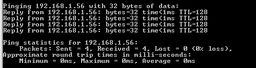
Imagine my satisfaction the first time I typed in, "ping 192.168.1.56" and got its responses. I watched it in WireShark too, it ARPs it first, then sends the ICMP. Interestingly, at first it took 23ms to reply, which I realized was the delay of sending out the debug data over UART. It dropped to <1ms once I'd disabled that.
This seemed like a fantastic moment to stop for a cup of tea.
TFTP
The TFTP protocol is like a super-simplified version of FTP. It uses UDP, but copies a smidge of the functionality of TCP. It starts with a Read Request (or a Write Request, but we're not interested in that) for a single filename. Then, data is sent in blocks of a fixed size, 512 bytes, which we have to acknowledge. The server will only send the next block after the previous block has been acknowledged. The last block is signalled by a length of less than 512 (zero, if the file was an exact multiple of 512).So far we have acted more like a server, responding to requests as they come in. To be a client, we need to initiate the communication, which means building messages from scratch. The basic order of operations is:
- find the hardware address of the first hop towards the IP we want to talk to. If it's not on the local net, this will be the address of the default gateway.
- wait for the ARP response, ignore everything else
- construct and send our TFTP request message
- main loop: read and process packets like we were doing before, but also decode the TFTP data blocks and write them to program memory.
- after the last block of data, jump to the main program, address 0.
Although we'll be sending an ARP request, we don't need to remember an ARP table. By constructing the next message in the same buffer immediately after receiving the ARP response, the MAC addresses will be filled in for us. The receive routine is already swapping the MAC addresses of every packet we receive, and I added into the transmit function the routine for writing our own MAC address in the source field. This means we can actually find the MAC address of our target even if it doesn't respond to our request. For instance, if we're looking for the default gateway, it's probable it'll be sending out other ARP packets which fill the same criteria, that is, its MAC and IP addresses. That's all we need to know, and our routine will use them just the same.
Having the transmit always add our MAC, and the receive always swap the MACs, might seem inefficient, but of course we're optimizing for words here, not cycles. Wasting a few hundred cycles doesn't matter, all that matters is using as few instructions as possible. Another thing to watch out for is that some instructions are longer than others.
I don't know how familiar the reader is with assembly, but in the AVR architecture, all instructions are 16-bit. But the addresses, for SRAM and prog mem, are also 16-bit. So if we want to jump to some address in memory, we would need at least 16 bits as an argument to the opcode. The jmp instruction does that, but as a result, it's a double-width instruction, at 32-bits. Most of the time, we only need to jump a small distance, and we use the relative jump, rjmp, or relative call, rcall. These simply say, "jump x words ahead", where x is small enough to fit into 16 bits with the instruction opcode.
Similarly, if we want to directly access SRAM, using lds and sts, we end up using two words for each instruction. The way to access SRAM in a single word is by using the pointers, X, Y and Z. "Load from address pointed to at Y" can fit into a single word. Then, we can jump about by using adiw and sbiw instructions – add/sub immediate to word. I'm usually cautious around these, since they look like they're single-cycle operations, but aren't. They're no faster than doing an add/adc. But they are single-word instructions, and can only add a small number onto the word, +/- 63.
Zipping the pointers around is needed to call our mem-swapping subroutines, but for direct access to different bytes in our packet buffer, we can use / abuse the memory displacement functions. These load/store instructions are intended for dealing with tabular data. If you're keeping track of a bunch of objects, all with a fixed number of properties, you can store them in memory as a table. By pointing a pointer to the start of the row of data, you can use the load-with-displacement and store-with-displacement instructions to access the different cells of the table for that row without moving the pointer. Then, advance by the width of the table to repeat for the next object. This is clearly a common enough operation that these instructions were created especially for it. The important point is that we can use these to reduce the number of words needed to do random access to our packet headers.
Loading an immediate address into a pointer takes at least two words, so by optimizing the order of operations, we can set them once at the beginning, and keep track from there, only ever making relative movements.
Writing the TFTP client took a while, since every last thing I did was optimized in some way. I won't go into every optimization here. Much like with the ARP and ICMP responses, once we had data coming in, it's just a case of modifying the packet to be transmittable. But the first part, the part that takes up the most program space, is building the requests from scratch.
The unique part of an ARP request is the ten bytes in the middle, which we'll just have to load from prog mem. The rest of it is addresses. But the addresses are so short that loading them as a separate operation might actually take more space than just having the entire first packet written out in prog mem. IP addresses are the worst, they're four bytes, so a routine to load it would have to be fewer that two instructions in order to take up less space than just repeating it. For this reason I ended up repeating our IP addresses in PM. I'd already written a routine to load our MAC address to the Y pointer, so I re-used that where possible. I also moved its data section to be within the first ARP request, just by placing the myMAC label inside it. The routine knows no difference.
I had at this point decided to have all the IP addresses hard-wired onto the chip. Later I might want to change this, the most obvious idea is to load them from EEPROM storage. But for now they're hard-wired, defined by preprocessor macros.
The TFTP responses, we can pull many of the same tricks in terms of re-using IDs and adjusting the checksum offsets. But the first request, we need to generate a checksum from scratch. Is it time to write a checksum subroutine? Nah!
For a start the UDP checksum is optional, and by leaving it blank we won't cause any problems. So it's only the IP header checksum that needs doing, and that's only checking the data within the header, not the whole packet.
There are a bunch of variables that affect the checksum here, the IP addresses of course, the ID of the IP message, and the length, which is variable. We do need to have a different ID for each message, and we have to come up with that ourselves. Instead of a random number generator, I just chose an unused register and dedicated it to it. On startup, the register is incremented, not initialized. This means through a reset, its value will only increase. It'll go back to its original value only after being powered off for a while. This register can be used both for the IP ID and the ephemeral UDP port.
But everything else about the checksum? The IP addresses and the length, although they change, are still hard-wired to the chip by the preprocessor defines. The length is only a function of the filename, which can be found using the preprocesor macro strlen(). So everything about the checksum apart from the IP ID will be fixed, which means, we can use the preprocesor to calculate it. Here's my IP-checksum-calculation using the C-style preprocessor macros:
#define IPmsg1ChecksumA (($45+$e6+$40+$40)<<8) + $97 + $11 + low(37+strlen(FILENAME)) + (myIP0<<8)+myIP1 + (myIP2<<8)+ myIP3 + (svIP0<<8)+svIP1 + (svIP2<<8)+ svIP3
#define IPmsg1ChecksumB (lwrd(IPmsg1ChecksumA) + byte3(IPmsg1ChecksumA))
#define IPmsg1Checksum ~(lwrd(IPmsg1ChecksumB) + byte3(IPmsg1ChecksumB))

.db high(IPmsg1Checksum), low(IPmsg1Checksum)
The first part does the shifting and the byte-grabbing to work out the word sum (since I'm using the length of the filename in an adiw instruction in the code, we already know it'll be limited to <63 bytes), then the second adds the third byte, equal to the carry, onto the main value to give us a wrapped 16-bit sum. We do that twice, just in case the sum was 0x1FFFF. The tilde does a logical not, the one's complement. And the .db writes the two bytes we care about into prog mem. An IPv4 header checksum calculation in two bytes!
For debugging, I actually plugged the ethernet cable from the ENC28J60 directly into my laptop. By default this causes a flood of DHCP and discovery messages, followed by silence, since the laptop can't determine what IP it has. This is simple to correct, just go to network settings, properties of the local area network, properties of IPv4, and change "Assign IP address automatically" to a manual set-up. I gave the laptop the IP address of 192.168.1.14.
Now it actually talks to the device directly, which means WireShark can monitor every packet. There's a feature that was initially turned off in my install of the program, which is to verify IP header checksums. This was very useful.
For the ACK message, we just cut off the payload, poke a few bytes and alter the checksum by the payload length.
By the time I'd got a perfectly-formed TFTP request and the acknowledge code written, we were up to 898 bytes used. However, this still had my debug code, and the ICMP echo code. Besides, we're nearly done.
I loaded up tftpd32.exe, which is a windows TFTP server and client. Needless to say, it was remarkably satisfying to see my program load a file over ethernet and spit it out over UART. Wunderbar.
Bootloader
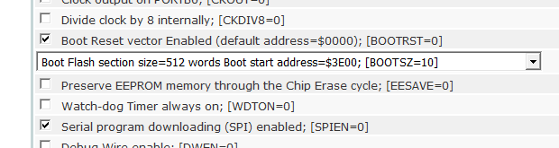
The next thing to do is to actually make it into a bootloader. I have no idea how you do this in C, but in assembly, it's very easy. You simply type.org 0x3e00 and the following code will be at that address – 1kB from the end of the 32kB that the ATmega328p has. There's also a fuse you need to set, if you want the reset vector to be at the bootloader section. This just means that when you power-on the chip, the bootloader runs first, not the application. I set the high fuse to 0xDC, for a bootloader of 512 words and the bootrst fuse set.
Now we need to take our data and write it to flash memory. There's a procedure for this, and a special instruction, SPM. The ATmega datasheet has example code for writing to flash memory. You have to write to it a page at a time, and the page has to be erased before it can be written to. One inconvenient thing, is that the pages on the ATmega328p are 128 bytes. Our data is coming in in blocks of 512 bytes, so it's not difficult, we just call our SPMwritePage routine four times. But four is the most annoying number.
If it were two, we could just call it twice. If it were eight, we could set up a loop to iterate. But the usual method of iterating is ldi, call, dec, brne. So iterating over four is the same amount of prog mem used as calling four times. However, I realized that we can do something clever. If we precede the definition of our subroutine with a call to that subroutine, and call that call instead, it will run the routine twice – first as it's called within the routine, and second as it falls through. So... for every call instruction we precede it with, it will double the number of times the routine is run. Like this:
SPMfourpages:
    rcall SPMtwopages
SPMtwopages:
    rcall SPMwritePage
SPMwritePage:
  ;
  ; ... code goes here ...
  ;
  ret
There we go, calling it four times, in just three instructions – saving us an entire two bytes. Yipee!
The flash page is pointed to by the Z pointer, and our Y pointer is aimed at the payload of the received packet. The TFTP format has a block number, starting at 1, which can be used to work out where to write in the flash. Simply decrement by one, so it starts at zero, then load it into the Z pointer's high byte and left shift by one, to effectively multiply by 512. Every block is acknowledged, and a new block won't be sent unless the previous one is acknowledged, so this method should function perfectly for writing all of the flash, assuming the TFTP server is functioning correctly. The only issue is if a packet is retransmitted, and we receive it twice, we'll write it to flash twice. This doesn't really matter, it's just slightly more wear on the flash page. (Update: later, I made the program check first, and prevent unnecessary writes to flash.)
I didn't bother doing a full erase of the memory beforehand. If the application being loaded is smaller than before, then part of the old application will still be there in memory. This isn't a problem, there is absolutely no situation where an application would depend on that data being erased. If you needed it to be filled with nops, you would specify that in the program. Similarly, if the application length isn't a multiple of 512, the last packet won't have completely overwritten the packet buffer in SRAM. So there may be some junk data written to the last page, after the end of the program, but it's completely harmless.
We need to serve a binary image of the application, not an intel .hex file. You can get the compiler/assembler to output this, but if you've only got the hex file, you can convert it to a binary file using objcopy.
avr-objcopy.exe -I ihex program.hex -O binary program.bin
In the final thing, we'll finish writing it to memory and then jump to address zero, to start running the program. But for testing I made it just hang (jump to own address) and the contents of the flash memory can be read out using avrdude. Easiest to read it in binary format then open it in a hex editor. Success! A TFTP bootloader in just 966 bytes.
Well, we're not done quite yet. TFTP states that both parties should retransmit if they don't receive anything within the timeout period. This is another signal to me saying that so long as the server is behaving correctly, we don't need to retransmit. But we do need to timeout if something goes wrong, and start over (or give up). I don't particularly want to use interrupts in this bootloader, it's possible to shift the interrupt vectors to the boot section, but this takes up space (even if we overwrite the unused vectors with code) and besides, there's a much easier way.
The watchdog timer is perfect for our needs, since it can actually be set to timeout in multiple seconds quite happily. I configured it to four seconds. Every time we transmit a packet, we reset the watchdog timer. If more than four seconds elapse, it'll restart the bootloader. By checking the watchdog-reset flag in MCUSR, we can tell if we're running for the first time, or following a watchdog reset, and count the number of attempts accordingly. This does mean starting over rather than just retransmitting the last packet (so, ARPing again) but the effect is the same.
The reattempt behaviour is quite simple. If we've not managed to contact the server, or haven't received any data, then after N reattempts, give up and run the main application. But if we have received data, we definitely do not want to give up, even if the connection fails, since we've already started overwriting the main program. So if data's been received, we keep retrying indefinitely. Finally we disable the watchdog, right before jumping to the main application.
By this point I was ready to remove my debug code, and enclosed it within #ifdef statements. Weirdly this caused the whole thing to stop working. It turns out that after resetting the chip, and during the loading sequence, we need to wait certain amounts of time. The debug routines happened to provide the delay needed. To write a dedicated delay function is pretty much the extreme of the type of optimization we're doing here – we want to burn as many cycles as possible in the fewest instructions.
Luckily I'd already assigned an unused register as a "zero" register, which should always contain zero. This makes some of the non-immediate instructions a bit easier to use, like add-with-carry. Now we can make use of it in another way:
wait:
  dec zeroReg
  brne wait
This wait function burns 768 cycles in just two instructions. The zeroReg is used as a counter, the first dec sets it to 255, and after the last brne, it will be back at zero. As long as we leave it zero at the end of every routine, we can always depend on it being zero at the start. If we wanted to lengthen this, a clever way of padding it is to add an rjmp to its own address plus one. This forms a single instruction, two-cycle nop.
More Optimization
With the debug code removed, we're now down to 856 bytes. Plenty of room. Don't know why I even bothered optimizing... but let's keep going! There are many optimizations still possible, some of them sacrificing readability. Something I was considering is compressing the data tables, and perhaps decompressing it at the start of the program into an unused section of SRAM. Unfortunately the type of data is not at all suited to run-length encoding. Huffman encoding could work, but the problem there is that the symbols are all different widths, which makes decompressing it a chore when we can only load from program memory in bytes. I've not tried it, but I'd guess the decompression algorithm would end up quite long. There's only ~150 bytes of data, so even if we got an incredible compression ratio of 50%, we'd have to decompress it in much fewer than 37 instructions to make a saving. And the result would be very difficult to tweak, whereas currently all the register values are spelled out nicely.All compiled programs start with an initialization of the stack. I usually skip this in assembly since, for any chip made in the last ten years, the stack pointer's power-on value is at the end of the ram anyway. Skipping this saves a few bytes, but I wasn't sure if there would be an issue with the retransmission. If the watchdog kept triggering while we're deep in subroutine calls, the stack could end up creeping its way down the memory. It would take a long time to cause any problems, since we've got 2kB of SRAM and we're only using, at most, the first ~600 bytes, right after reading in a full data packet. But the infinite-retransmission scenario made me wonder if this was a problem. I wrote a simple program that pushed onto the stack a few times and then let the watchdog time out. As it turns out, the stack resets correctly by itself, so we needn't have worried. But it's nice to know that the stack-pointer setup code is completely unneeded.
A compare is just a hypothetical subtraction. When you write cpi r16, 10 you're asking, what would the status register be, if I subtracted ten from r16? The tst instruction is just a compare with zero. Now when we come to words, there is no compare-immediate-with-carry. Thus the usual way of testing if a word is zero, would be:
ldi r16, 0
cpi XH, 0
cpc XL, r16
Since in this program I've set up a dedicated zero register, that reduces to two instructions – but we can actually test it in one. It's just a hypothetical subtraction, so why not perform an actual subtraction?
sbiw X, 0
This works perfectly, and leaves X unharmed since subtracting zero has no effect. Keeping this in mind, there are some situations where we load the register, compare it to some value, and immediately take action. In those cases there's no point remembering what the value was, and we can perform an actual subtraction instead of comparing. Each time we do this, it shaves off another two bytes.
AVR, as an architecture, is not "orthogonal". The lower 16 general purpose registers are not "immediate" and can only be used with certain instructions. This is why we almost always use r16 and up as our main temp variables or accumulators. I normally assign many of the lower registers as certain variables which I want to access quicker than SRAM. At the end, we can see which ones were used most, and set those to be immediate registers, if there are any left. This improves both speed and mem usage, since we can go through and substitute immediate instructions.
Some of the optimizations are less optimizing and more corner-cutting. Most notable is the fact that I'm not checking every field of the packets we receive. ARP is ok, since it isn't used for anything other than IPv4 as far as I know, so if the EtherType is ARP that's all we need to check. If another type of ARP came in, it would be rejected when we tried to read the IPv4 address field.
A more severe cut of a corner was not checking the source IP address we're receiving the data packets from, just the port number. The port number is what identifies the transaction, and we'd never be contacting two separate TFTP servers within the same time window. It does raise a question of security, someone listening on the local network and wanting to sabotage the transaction could inject their own packets which we'd happily write to memory. But in that situation, adding extra IP address checks would add no security at all, since they'd probably be spoofing those anyway.
TFTP is not a secure protocol, and makes no claim to be, so adding security checks is kinda pointless, or worse, gives the illusion of security. The only way of securing it is to keep the TFTP server on the local network, and assume there are no malicious parties within. I imagine that's the ordinary use case of TFTP anyway.
We're not checking the data in any way when it comes in. The ENC28J60 filters out packets with bad CRCs, but that only covers the last leg of the journey. We're ignoring the IP/UDP checksums, so perhaps verifying these would be worthwhile. But my home router, like most networks these days, is using NAT, which swaps IP addresses as they pass through. As a result it will have recalculated the checksums right before they arrive at our breadboard. So, I assume that packets with corrupted checksums would get thrown away at the router.
It is worth checking the length of the data, I mean, we don't want to overwrite the last kilobyte of flash, so ignore every data block after 62, which would be 31kB. I'm only checking the low byte, if you sent a very large file with more than 255 blocks, it'd start writing to flash again, but that would be your stupid fault for retrieving such a file. The check is only there in case a compiled binary intrudes into the bootloader space.
Talking of working it on the local network, at this point I was ready to bite the big cookie – bootloading a file over the public internet. Only then can we call it an internet-of-things-thing!
The Field
Setting up a public TFTP server is actually quite hard. It's not possible on my shared webserver space, so at first I asked a friend to set one up at his house. He has a NAT, so port forwarding needs enabling for port 69, but additionally, the ephemeral port that the data is sent out on. NATs track connections, and TCP is very easy to track, what with the starting with a SYN and ending with a FIN. But TFTP is over UDP, and beyond the first packet it does not use registered port numbers.My solution to enable this was to edit the pool of port numbers the TFTP server can use, and limit it to a single one, by entering 3000:3000. This means the response is guaranteed to return on port 3000, so if we set up port forwarding for that port too, the ACKs will make it to the right host.
We were able to load a file, eventually, but I wanted to experiment more. Really, I need control over both computers. On my home network, I set up port forwarding for SSH into a raspberry pi. Then, I grabbed the breadboarded ATmega328p/ENC28J60 and headed out into the field.
From a different internet connection, many miles away, I SSH'd into the pi. I knew the IP address, since I'd already set up a cron job before leaving that would cURL a PHP file on mitxela.com every hour. The PHP file takes note of the $_SERVER[REMOTE_ADDR], and accessing a different URL on mitxela.com redirects me to that address. Like a tiny, crappy DNS server, but a quick and effective solution.
My friend informed me about UPnP. A higher-layer protocol that's usually associated with media servers, it's actually possible to use it to configure most home routers. With the correct UPnP client, you can enable port forwarding in a generic way that doesn't depend on router specifics. There wasn't a UPnP client in the raspbian repositories, but a project exists called MiniUPnP that we can install from source. This is as simple as downloading it using wget, extracting it using tar, and typing make followed by sudo make install. Exciting. Now by typing:
upnpc -a 192.168.1.67 69 69 UDP
we've enabled port forwarding for port 69 into the raspberry pi. Note: one helpful google result reminded me of how easily you can grab and split strings on the command line in linux. Ah... piping. By calling ifconfig, grepping for the address and cutting it out, we can form our UPnP command in a way that'll automatically fill in the IP address:
upnpc -a `ifconfig wlan0 | grep "inet addr" | cut -d : -f 2 | cut -d " " -f 1` 69 69 UDP
This means we could actually set up a cron job to maintain these forwardings even if the addresses change. I forwarded port 3000 too, then apt-get install tftpd-hpa to grab a TFTP server. Lastly I edited its configuration file, located at /etc/default/tftpd-hpa, and added to the options line "--port-range 3000:3000". Note: if you're doing this for more than just testing, it's probably a very good idea to give it more than just one port to operate on. But every port in the range has to be forwarded, of course.
Public TFTP server enabled. I love the fact I was able to set all of that up remotely.
At this moment I realized the router my laptop was connected to (wirelessly) was physically located at ceiling-level. I need to power the breadboard from my laptop's USB, but I only had a very short ethernet cable. Not a problem, we can plug that into the side of my laptop and enable a network bridge. Note: this is different to "internet connection sharing", where the laptop behaves as a router/DHCP server. With the wifi and ethernet ports bridged, plugging the breadboard into the ethernet port should behave exactly as if I'd plugged it straight into the router.
And this was a bit of a forehead-slapping moment for me, because I realized with it set up like this I can monitor every packet it sends and receives in WireShark as it passes through my laptop. I should have done this sooner.
With everything set up, I turned the chip on, and rather anti-climatically, it worked perfectly. It ARP-requests the gateway's MAC, receives the response then sends the TFTP request for the file to my home network's IP address. Then it receives the file and writes it to program memory.
Time for a celebratory cup of tea, I think.
EEPROM?
It's fair to say, if you're using an ethernet bootloader, the chances are, your main application will also be using ethernet in some way. It's not unlikely, then, that there's a full DHCP client in the application section.A very attractive option is for the bootloader to load its IP and other settings from the EEPROM section. Then, if the application's DHCP client is assigned an IP, it can store it to EEPROM for the bootloader to use also.
My main reservation about building it this way is that the bootloader is no longer bulletproof. If the application mucks this up in some way, the bootloader could be left in an unworkable state, and the only recovery option would be to connect up an ISP cable.
(Another non-volatile but editable way of storing settings would be to put them into a page of the application section flash, say, the last page before the bootloader. This'd be semi-permanent, but manually changeable over ethernet, by filling in that last page in the binary file served. Ordinary-length applications wouldn't overwrite it, only ones which specifically go into that page. The danger is if your application just happens to be very long, and intrudes by accident. While this feels more rugged than the EEPROM way, it doesn't let the application dynamically change the bootloader's IP, so it's not really all that useful.)
We've currently got about 170 bytes of free space. The first thing to do is rewrite the bootloader to use IPs stored in registers, rather than hard-coded. If we choose not to use the EEPROM, we can just load constants into them. I moved some definitions around and assigned the lowest twelve registers, r0 to r11, as the three IP addresses we need to store (my IP, gateway IP, server IP). Most of the changes are straight forward, replacing ldi with mov. Actually, in several places we can now optimize further, using movw to shift two registers at a time. There was a fair bit of reshuffling, but in the end, with the IPs no longer stored in program memory, the result was actually shorter than before. However, there's still the hardest part left to do, which is the IP checksum.
Adamant not to write an actual checksum routine, having come so far without one, I continued in the name of precalculating checksums and subtracting the adjustments. In this case, it's now the eight IP bytes and the IP ID. Although we need to wrap every carry operation twice, luckily we can overlap all of the carrys with loading new data.
    ldi r25, high(IPmsg1Checksum)
    ldi r24,  low(IPmsg1Checksum)

    sub r24, rMyIP1
    sbc r25, rMyIP0
    sbc r24, rMyIP3
    sbc r25, rMyIP2
    sbc r24, rSvIP1
    sbc r25, rSvIP0
    sbc r24, rSvIP3
    sbc r25, rSvIP2
    sbc r24, ephReg
    sbc r25, zeroReg
    sbc r24, zeroReg

    st Y+, r25
    st Y+, r24
Most definitely ripe for optimization, or, you know, swallowing my pride and doing it properly, but we'll worry about that in a bit, this is good enough for testing.
The next thing that could potentially take up loads of space is copying the data from the EEPROM to the registers. The EEPROM has its own address space, starting at zero. Something that's often forgotten is that the SRAM's address space is shared with all of the registers. The SRAM starts at 0x100, before that are the extended IO registers, the IO registers, and... the general purpose registers. That's right, we can change the value of, say, r15 by using the load/store instructions on address 0x00F. Crazy, huh?
So if our IP addresses are stored at the start of the EEPROM (address 0) and our registers to work with them are r0 and up (address 0), we can load them all in a single loop copying from one data space to the other using the same address pointer. Saving us... ooh, a goodly number of bytes.
With that working, it was surprisingly painless to give it hard-coded backup addresses, if the EEPROM isn't present. There was still so much space left in our 1kB, that I added something I assumed I wouldn't have a chance to do – automatically choosing which IP to ARP. For this we need a subnet mask. The operation I'd been dreading looks surprisingly innocent in pseudo-C:
if ((server_ip & subnet_mask) == (my_ip & subnet_mask)) {
  gateway_ip = server_ip;
}
(Strictly speaking, it should be first_hop = server_ip, followed by else first_hop = gateway_ip, but as it's only used once, we may as well overwrite the gateway variable.) The trouble of course is that the IPs are 32-bit and our processor is 8-bit. I bet if you compiled that, it would end up using the stack as an intermediate, resulting in 8 pushes, 8 pops, 8 pushes, 8 pops, etc. I put the IP-loading code into a subroutine, and made it destroy our IP registers in the calculation, then call the loading routine again. Without optimizing the repeated 8-bit ANDs, this came out at 18 instructions (36 bytes).
I was ready to optimize this right down, do some clever looping, but actually we're only at 964 bytes, and to be honest, we're done. I ran a number of tests: loading from the local network, loading from the public internet; using hard-coded addresses, using eeprom data. All of the functionality I was hoping for is there. I was hoping to have to squeeze the last few instructions in by recursive optimization, but, well, we were so cautious on the way here, it's finished up embarrassingly roomy. Ho ho ho.
Possible other features to add into the last few bytes:
- Load the filename from EEPROM? Not sure how much point there is to that. Variable filename length would mean extra work in a few places, but nothing we can't handle.
- Alter the loading method so we don't have to read the entire packet into SRAM. This would let the bootloader be easily ported to smaller chips. For the data blocks, just read the header, then load the payload directly into the SPM buffer.
- DHCP client? I'm sure we could squeeze it in, if we really tried.
For now though, I'm going to declare this project "completed". Next on the agenda is making some software to be loaded by the bootloader. Yep, I'm ready for it, a webserver in assembly. Stay tuned.
Update: I thought of something else to add. The flash memory has a limited number of write cycles (about 10,000) and it's therefore best to avoid writing to it repeatedly without reason. Depending on what the application is doing, it may want to check for updates on a very regular basis, which means triggering the bootloader a lot. I assumed that you could just take the tftp server down when you didn't want it to update, but actually that's really inconvenient if you've got lots of devices in the field. Instead it's much better to download the file, and check if it's different. This is easy to do, since right before writing to it, we have two pointers set up ready to write the page, we can just read both and compare each byte. If they're the same, don't do the write. Simple, but this means we can now trigger the bootloader as often as we like without worrying about flash wear.
Another addition, I made the very beginning of the bootloader disable interrupts and reset the stack. This isn't needed if the bootloader started from a reset, or a watchdog timeout, but a lazy application may start the bootloader by simply jumping to it, in which case these instructions make the system a little more durable.
Total file size now: 1000 bytes. (Of which 11 are the requested filename, "program.bin".)
Video
How to use the Bootloader
You will need an ATmega328p and an ENC28J60, wired up as follows:
PB1 <--> INT
PB2 <--> CS
PB3 <--> MOSI
PB4 <--> MISO
PB5 <--> SCK
I've only tested this with the ATmega chip running at 16MHz. Running faster than that, you may need to alter the wait routine, and possibly the SPI prescaler. If anyone wants help porting this to another chip, let me know.
The source code is on github. I also uploaded a compiled hex file, which if you're planning to use the EEPROM settings, may be usable without changing the config.
By default, the bootloader will try to load the settings from the EEPROM, but if it's empty, it will use the hard-coded backup settings. The first few lines of the .asm file are the configuration. You need to give it a MAC address, an IP address, the addresses of the TFTP server, default gateway and the subnet mask. If you want it to have hard-coded settings, and you're using this on a home router with NAT, it's easiest to check the router settings to see what the DHCP pool is, and give the device an IP outside of that range.
You can optionally change the filename that it requests, this can be up to 31 chars. You can also set the number of reattempts if it can't immediately contact the server. Just after powering on, it may take a few seconds for the ethernet link to establish, so the first few packets may be lost. But too many reattempts means a longer delay before giving up and starting the old application, if the server is actually unavailable.
To use the EEPROM settings, simply fill in the first 16 bytes of the EEPROM with the device IP, server IP, default gateway IP and subnet mask, in that order. You could do this by creating a binary file in a hex editor and writing it to the EEPROM using avrdude, eg -U eeprom:w:"IPs.bin":r with the 'r' type for raw binary. You could also do this by adding an .eseg section to the assembly file which should produce an .eep file in hex format. But the main anticipated method of setting the EEPROM addresses is by writing to them from the application itself, for instance, if it's running a DHCP client.
Beware, if your application uses the EEPROM for something else, the bootloader has no way of knowing if the data there is valid, it only checks that it's not erased. If you don't want to use the EEPROM for these settings, I would recommend disabling it.
If you've never used AVR assembler before, I think the easiest way to build is to use AVR Studio (or Atmel Studio, as the later versions are called). You can simply select new project, 8-bit AVR assembly. The single .asm file is all you need, there are no dependencies. You can also assemble from the command line with something like
avrasm2 -fI -o "kiloboot.hex" kiloboot.asm
You then need to burn this hex file onto the chip and set the correct fuses. The important one is to set the high fuse to 0xDC, with the avrdude command -U hfuse:w:0xdc:m This configures the reset vector and the bootloader section to be 512 words.
Next you need to set up a TFTP server. For windows I recommend tftpd32, for linux I used tftpd-hpa. It's straight forward if you only want to boot from the local network, but making the server publicly accessible is not trivial. See the earlier section of this project entitled The Field.
The server needs to host a binary image of your application, not an intel hex file. There will be an option to configure your compiler to output a binary file, but if you've already produced a hex file, you can convert it using objcopy:
avr-objcopy.exe -I ihex program.hex -O binary program.bin
The last consideration is triggering the bootloader. This is up to your application to manage. The bootloader will run once on powerup, and after each reset, but not while the application is running. The two obvious methods would be to either run the bootloader on a timer, or have some user-driven aspect of the application trigger it. For the timer, beware that if the server is unavailable, it has to wait the full timeout period (default is 16 seconds) before returning to the application. If the server is up, the whole download should take a split second as it's only a few kB. If the file hasn't changed, it's still downloaded but not written to flash, to avoid unnecessary wear.
I think the simplest way to jump to the bootloader in C would be
asm("jmp 0x3e00");
There's probably a fancy C way of doing it, but this is the only way to be certain of what it's generating.
That's all, folks.
ø”.ï.¿.à.¿.Ñ. . . ? L ] n . ....&.7.?·.Ñ?¿.ôB.S.î$ÿ$Ý$os.·.ÿw'¨• Ô¾#à.'.ár..â.“`..“`.s0.ô.”..s•c•.â.¹*š)š.å.½.à.½.ï.à1Ñ°âSÑ.—é÷ìå ÿçJâ.‘.‘'ÑJÑJ•Ñ÷ÑàÀà.à.ïØ¢.“.•á÷.á9Ñ0Ñ&–‰’™’©’¹’:â©ÐÒÐ80é÷F0Ù÷.– „..Ñ…..Ñ©÷d—.à#Ñ”å.ë....ƒ.’.….”.‡.–.†.....™“‰“.ÑI’Y’i’y’.á.Ñ«—hƒ h‹>ã€Ð©Ð80é÷F0‘ôh–õÐÁ÷e—...0¡÷.à.“±à â*àÝÐ*—ñÐ9âjÐéÏ@0é÷`–áÐÑ÷$— ±àªá$àÎÐ.—.‘.1‰÷.….0....a÷.–"àÂÐ.‘.‘.—.à.ƒ.à.ƒÚ‚Ü‚Ý‚d—Ø‚.â.ƒ¸…©… ¨.¹...©‡¸‡m–ù‘ÿ3 ôú•ÿ.î'.—yð?/>_E‘.‘...àó.Ñ÷.#.ð.ÀòPÒPtà.Ð>â$Ð’0 ...ô Ïsà:Ï.Ð.Ð.à.Ð.Ð äÐ......à.Ð2–*•É÷àXð@.à.ÐàXÿO...á.Ð.•.·.ýýÏ .¿è•.•¨•.'.áeÐ.ÿ.À.áaÐ.ÿ÷Ï.é.è\Ð.ëZÐñÏ.ä.ï)áPÐ.ä./.•*áKÐ*˜.çBÐ@Ð 3•ÑàÆàdÐ,—.‘:Ð:•á÷*š.é.à?À.™þÏ.ä.-/-4Ð*˜.ã+Ð)Ðà.'Ðð.%Ð /#а/.—Í. .—qðÓàÀà½.¬..ôÞ.ÑàÀà.Ð.Ð.Ð.“.—á÷*šÑàÆà±à à&à.Ð9‘I‘.ä.-/-.Ð.é.ä.À .'.½.µ.ÿýÏ.µ.•.“.Ð.‘.•./*˜óß./ñß*š.•.‘...“.“*•Ñ÷.•.”)‘ .)‘!..•€. øß..÷Ï.’.’)’9’.•êëÿç.à.‘.“.•á÷.•Ú”ñ÷.•ª'»'í.ù™þϲ½¡½øš.µ.“ 1¹÷.? .ð.•ìäÿç.áåÏÀ¨..À¨..À¨.þÿÿÿ.¿.H.I.LþM.JþK.DÿE.FÿG.Ÿ.X°H?I0PùQ÷Ÿ. D.E.B.C.@.A.¿.@.A.‚0F.G.D.JDK.T.V.W.T.V"W1›ÀŸ.¿................. ..E..0æ—@.@.â½.E......program.bin.octet.