Keytar
31 Dec 2014Progress: Suspended
It's no secret that I'm building a keytar. I wanted a midi controller that could match the sound of my Reverse Oscilloscope synthesizer.
My original plan was to make something similar to a Korg RK-100 (in my opinion, the best looking of all keytars), with the following additions:
• More midi controls - velocity and aftertouch, sliders and so on, but also a means of inputing waveforms. Some kind of touchscreen or drawing surface.
• Lights - each key could be cast in acrylic, with an RGB LED at the root. They could be automatic when playing, or better, midi controllable.
• On board computing - could it run the reverse oscilloscope as a stand alone synth?
• Pyrotechnics - almost forgot to mention this one. It has a flamethrower in it.
This was not going to be easy. After tossing ideas around for months, I eventually decided that I would start simple. That meant, just trying to build a test keytar to begin with, and if successful, Mark II could add the flamethrower, the midi input for lights and so on.
Incidentally, given that I'm writing this up about two years after the pictures were taken, it should be pointed out that at the time, building a modern version of a Korg RK-100 was quite a cool idea. The original was rare, expensive and did not even have velocity sensitivity. But earlier this year Korg announced that they were going to re-release the RK-100, with updated controls and a built-in synth. I am not sure how I feel about this. Maybe my efforts inspired them!
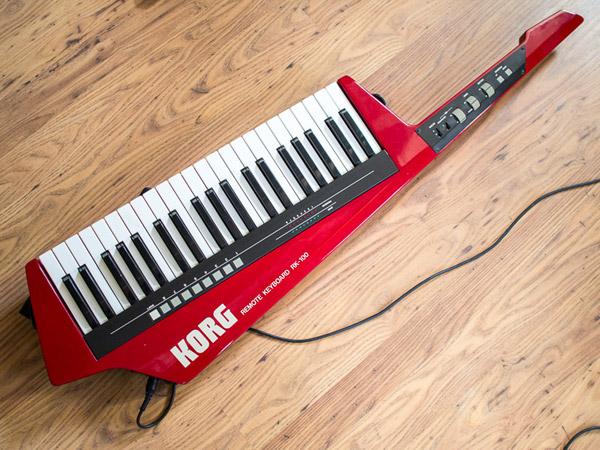
The original Korg RK-100
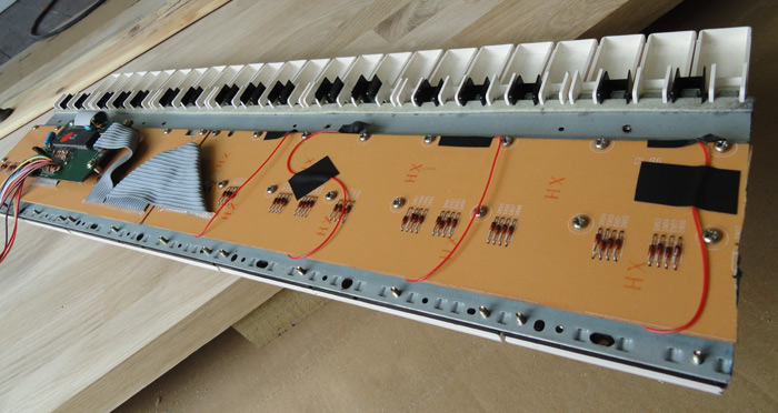
So, for the build I decided to sacrifice a donor keyboard, an Evolution MK-149, because I had two of them. They're very cheap so there was limited risk involved. In retrospect, given the effort put into the project, I should have gone with something better.
49 full size keys is a little too much, so after dismantling the keyboard I sawed the end off. This is an OK thing to do as long as the matrix remains intact. In this picture, the keyboard is upside down, the sawn edge is on the right, and the red wires are jumpers I've soldered which let the matrix continue to work.
That was the easy part. All of the controls, specifically the mod, pitch, and volume pots, needed to be relocated. Annoyingly the volume control was soldered straight to the power supply board. The connectors all also needed to be relocated, and for now I just decided to put everything on extended wires which could be shortened later when the internal layout was finalized.
I decided to place the main control board directly underneath the keyboard instead of adjacent to it. Overall I reduced the size of the keyboard by about half. There was a lot of tedious soldering and to be honest the pictures are a bit dull so I'll skip to the interesting part: the wooden body.
I had acquired an offcut of an oak worktop. I would be routing the body out of this entirely by hand. It was only an inch thick so it needed two layers, and the piece I had was not big enough to cut two keytar-sized lumps out of. So I decided to cut four shapes out and glue them together, two for the top layer and (staggered) two for the bottom layer. A better decision would have been to cut one full sized piece for the top layer and make up the bottom layer from scraps - after all, the top layer is the one that's most visible. But I would be painting the result, so the main concern is overall strength, not appearance.
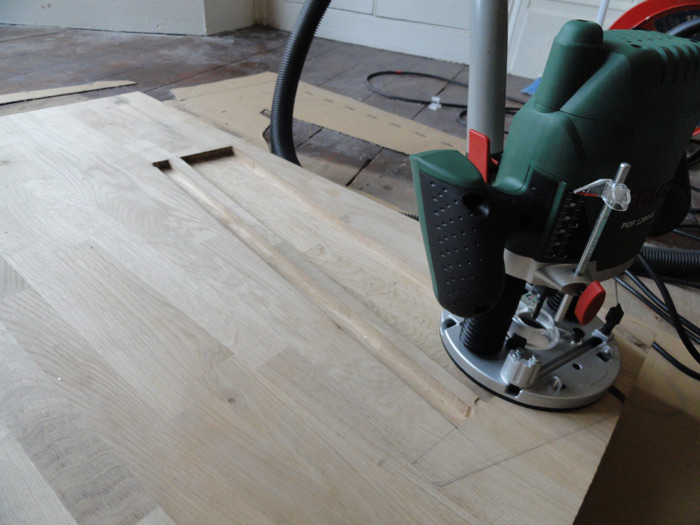
Having laid out the design, I started by routing out the recess for the main circuit and the well for the keys. Did I ever mention that I love routing things by hand? This was actually my first experience of it. I'd used CNC routers, where you just press a button and watch. But doing things by hand is just so much more satisfying. It is the perfect fix for a control freak like me.
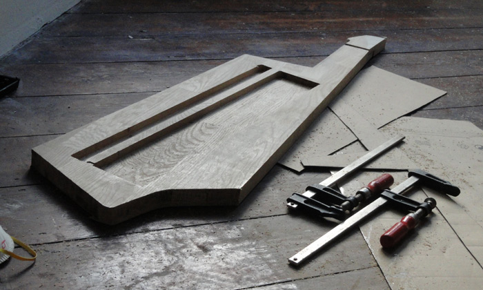
The bottom layer finished (yes, there are a couple of mistakes, but they won't be seen) with the neck split as far along as possible. This should give the neck some strength as the top layer will be hollowed out for the controls.
Now for the top layer. Where the join occurs, I routed half the thickness away for a bit so that it'd really get a good hold. It is fiddly to get two parts to mate exactly like this though.
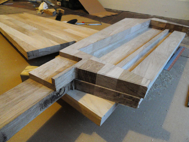
This is all only cut out in rough, of course, with about an eighth inch spare round the edge. Still, with the last bit of the neck roughed out I could not resist a mock-up with the keys (no electronics yet though):
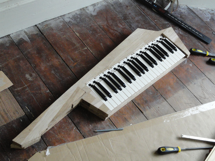
In its unfinished state, the neck looks pretty brutalist in design...
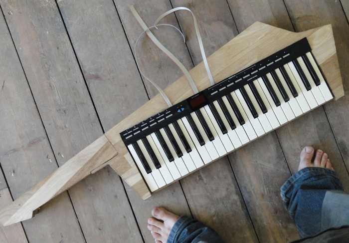
And one more, with the control panel in place (those are ribbon cables coming out of the top) and indeed my feet making their debut appearance on the site.
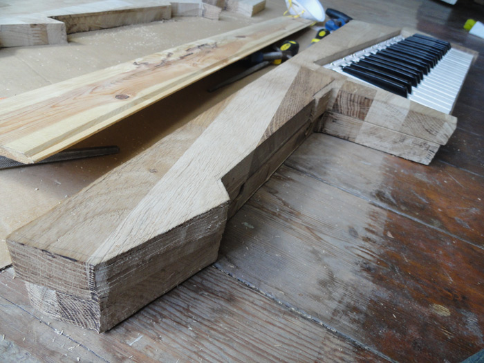
I glued the neck parts together but a lot of thought needs to be put into the layout before we close the top and bottom layer forever. I hadn't really made my mind up about what would be on the neck, but I knew that whatever it would be, running cables through is going to be much easier if we do it now rather than later.
There's also the momentous task of fitting all the circuit boards in. Even with all of the resoldering and rearranging it was going to be a very tight squeeze.
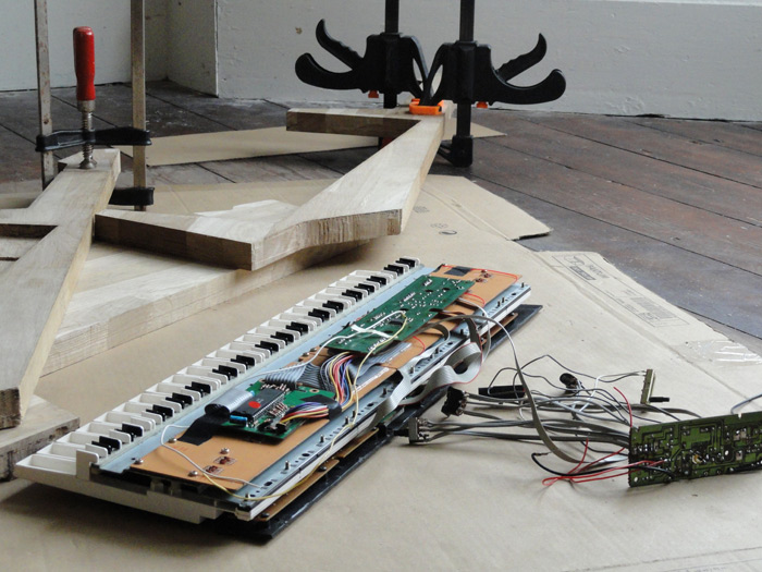
I planned to fit the power supply board (on the right in the picture above) into a hidden cavity in the body of the wood. The space I routed out for it was easily big enough in principle, but with all the wires attached it ended up terribly difficult to get in and out. The cavity has a passage for more wires, which pass through to where the connection panel will be mounted (midi, power, sustain pedal jack).
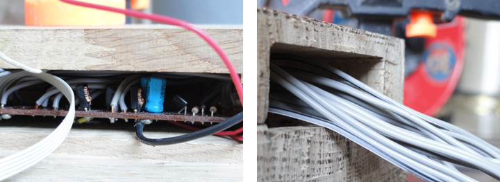
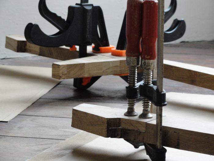
For the neck, still undecided, I just ran a hole through it which would let me thread wires in later. I wasn't sure what else I could do. And, confident that I had done the best I could to plan ahead, the moment came to glue top to bottom. Using all the clamps I could find.
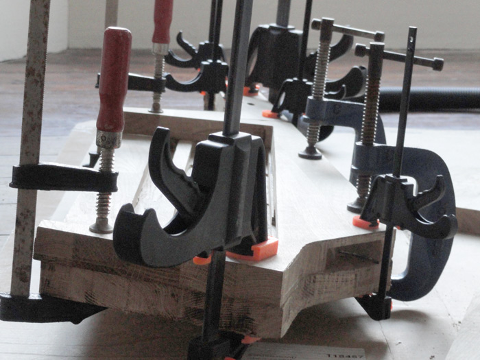
Those little quick-grip ones? they're useless. Absolutely worthless. The big ones are okay, and for one-handed application have their merits, but if I could switch them all for F-clamps I would.
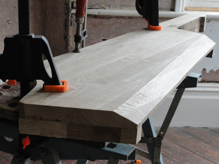
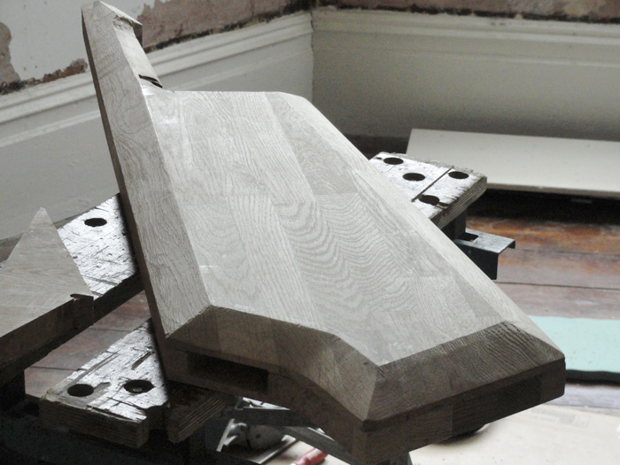
So, when the glue dried it was time to start planing. There was still a lot of material to remove. I wanted to produce a nice, clean, polygonal form. Long flat bits are easy to do:
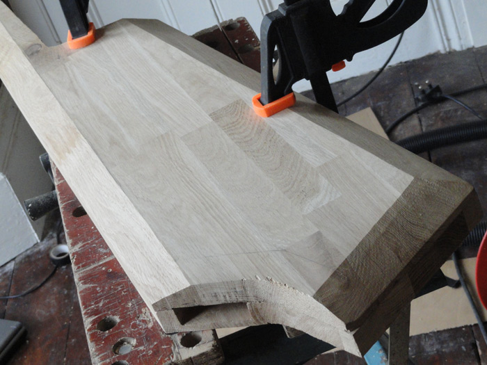
The end-grain adds a little difficulty, but curves are where the real challenge lies. I did the most awkward bits using a rasp and then a file. Unfortunately, as I began on the neck, I discovered a major flaw in the chosen piece of wood.
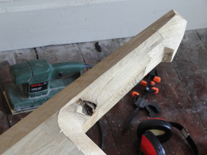
A great big void! It was completely invisible before I started cutting. I decided not to worry and filled it with generic filler. As for the rest of the neck, I was not at all certain as to what shape it should be. It needed to be rounder and thinner. But it could wait. The bulk of the woodwork was done.
Having filled and reshaped the back of the neck, I mounted the electronics, added a strip of felt under the keys, fitted a strap, and that's about as far as I got. It is a playable instrument, but the dangling wires from where the socket panel will be are a little delicate, and the completely unfinished neck is nothing but decoration for now. I did think about adding extra knobs, little potentiometers in place of where a guitar would normally have its tuning pegs. That would be sweet. A ribbon controller for pitch bend would work well. It also needs painting, not that the oak is all that ugly.
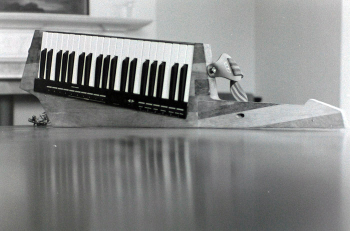
Since this build-log ends so abruptly, I thought it would be fitting to post a picture I found on a roll of film I developed recently. The keytar, the day I first wore it and made music, an image preserved in silver. I haven't progressed since then, but perhaps Mark II will appear in time.