
JV-1080 Encoder Repair
21 Mar 2020Progress: Complete
The Roland JV-1080 is a popular rack-mount synthesizer from the 90s and on this particular one the rotary encoder on the front had broken.

On the face of it you might think repairing or replacing the encoder would be a doddle but let me assure you, this repair is far from trivial. The very first and most important problem is that it isn't really an encoder, but a rotary pulse switch.
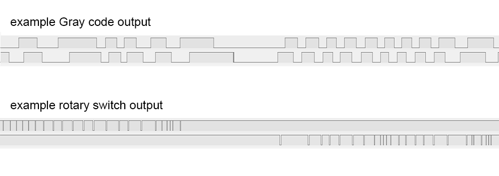
Regular rotary encoders, the type typically found on most devices, use a 2-bit quadrature output known as a Gray code. It encapsulates both the speed and direction of rotation in a way that has become standard and — at least in theory — easy to read. The rotary switch on the Roland synth is still a purely mechanical device, but it has two outputs, one for each direction, and outputs a single pulse for each detent.
We're apparently not the first people to run into this problem, and while it might have been possible to source a working replacement it seemed like the easiest option would be to use a modern encoder, drop in a microcontroller and emulate the behaviour of the old rotary switch.
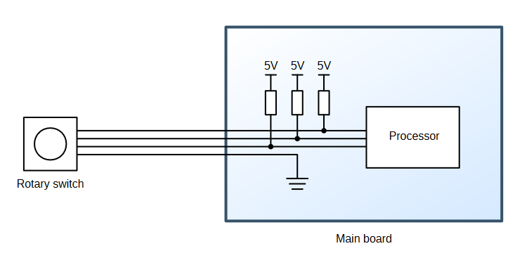
However, the part lives on the end of a four-wire ribbon cable that consists of ground and three signal wires (the third signal is for the push button). The switch, being a mechanical device, just shorts each signal to ground as needed. There is no power supply available.
Yes, yes, we could just poke around on the main circuit boards and find a 5V rail to hook into, solder an ugly bodge wire and power the chip from that, but if that's the direction we'd chosen it would hardly be worth writing about. No, the challenge posed was this: could we produce a drop-in replacement encoder, that emulates the rotary switch behaviour through digital logic, but that doesn't draw power from anywhere else? Something that appears to function as a completely passive device. Could it be done? Let's find out.
Reverse engineering
Some quick investigation showed that the signal wires were weakly pulled up to 5V on the main board.
Touching the signal wires to ground produced some jumpy responses on the display, so the first task was to work out what pulse length we need. With an ATtiny I quickly figured out that grounding the wire for about 1 millisecond was as short as we can go. The synth appears to be listening for a rising edge, but it's only sampled at a fairly slow rate, possibly for debouncing. Holding the connection down for longer did not have any effect, but shorter than a millisecond and it starts to become unreliable.
I recall from the last time I used one of these that spinning quickly caused it to jump in units of ten at a time, but now I'm completely unable to recreate that effect. I'd thought it would be triggered by very short pulses, or pulses in very fast succession, but nothing seemed to produce any different behaviour now. I may be remembering a different synth.
Using a multimeter we measured the short-circuit current on the rotary switch wires to be ~100μA, which implies a pullup resistor of 50K. For some reason the button signal has a 20K pullup, providing more than twice the current, so we could tap into that if we have to, but I'd rather keep the button entirely separate.
Plan
Build a circuit powered purely by those 50K pullups. Realistically, any digital logic we add needs to draw much less than 100μA to have a chance of working.The ATtiny13A is an ideal choice of microcontroller for this task. Its limited resources mean it draws very little current. But even so, in normal use it expects about half a milliamp so we'll need to come up with some extreme power-saving tricks.
Using a diode we can trickle charge a capacitor to act as a power supply for our circuit. But better than that, we can use the built-in ESD protection diodes to do this job for us. Here's a reminder from the datasheet:
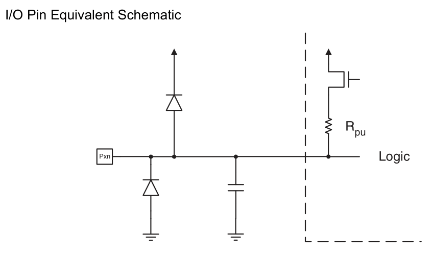
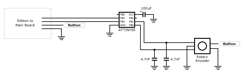
Any voltage outside of the power rails will end up on the power rails (minus the diode drop). So we connect our capacitor (and only the capacitor) to the power pins, and the signal wires to the GPIO pins, and the power circuitry is sorted. The simplicity of the resulting schematic borders on the absurd.
The new encoder is wired straight to the GPIO too. The ATtiny's internal pullups are also around 50K, but silicon resistors have dreadful tolerance (usually 50% or worse) so we'll see how that goes. If needed, we could tri-state the GPIO pins and add external resistors. We could probably get away with 200K or higher, since the distance is so short and there aren't really any noise sources.
I'm familiar enough with cheap gray-code encoders to know that hardware debouncing is totally worth it, and in its simplest form is just a couple of capacitors across the pins. The time constant will depend on the strength of the pullups, I chose some 4.7nF caps because they were the first ones I found of roughly the right order of magnitude. The best technique here is to scope the line and see how clean a signal we're getting, and the 4.7nF caps seemed fine.
There are more elaborate ways of debouncing but I find this setup simple and effective. If we did switch to external pullups we'd need to adjust the debounce caps, of course.
Execution
At least a dozen methods exist for interpreting the Gray code. As far as I'm concerned, it's vitally important that one detent of rotation corresponds to one pulse of movement in the output.Some methods of reading the encoder skip some of the states, this is viable for menus and things where precision is not too important. In a single detent, the output cycles through all four possible states. My preferred method is to follow every state with a counter, and register a movement when the counter reaches four. This has some amount of debouncing built-in, since a flicker on a pin will count backwards and then forwards again. Assuming you don't miss any changes.
The final bit of logic to add is to explicitly reset the counter when both lines are in the idle state. Experiments have shown that spinning the encoder back and forth as fast as possible can lead to the occasional missed step. This check invisibly puts it back in sync.
Again, there are other ways of doing encoders, but this is a way that I've found to work well.
In an attempt to reach a wider audience here I'm writing this in C, instead of my usual obsessive assembly.
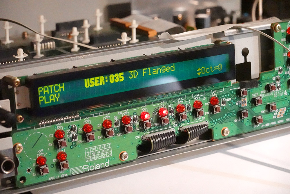
The ribbon cable mounts to the board with some type of ZIF connector. My replacement bit of ribbon cable was not quite the right gauge, but it worked well enough. Before long I had the encoder working and generating pulses to the synth, while powered from a steady 5V on a breadboard.
Sleep mode
With all the peripherals disabled and the chip in the deepest sleep mode, the ATtiny13 uses virtually no power at all (something like a few nanoamps). The pin-change interrupt is one possible wake-up source, which is handy, as we can wake up only when the encoder is turned.Specifically, we want to wake up on the edge transition, note it, and immediately jump back to sleep. But during power-down mode the main oscillator is stopped, and for waking up it can take tens of milliseconds to get started again.
Luckily there's a secondary oscillator used for the watchdog timer, and by necessity this oscillator won't stop in sleep mode. With the right fuse settings we can run the main processor from this 128kHz oscillator, and not only will this underclocking mean a serious reduction in power consumption, it will speed up the wake-up process too, since the oscillator remains running.
It's possible to combine this with the DIV8 setting to underclock further still, but there's little point in doing so. The process of { wake up, calculate, go back to sleep } will use a roughly fixed number of cycles, so it'll use a roughly fixed amount of energy. As long as our capacitor is up to scratch it won't matter.
The encoder logic was written specifically with this wake-up behaviour in mind, using the generic PCINT interrupt. It's fired when any of the pins it's monitoring are changed, but it doesn't tell you which of them has changed, or how. The INT0 interrupt can be much more specific, but we only have one of them, so it's more hassle than it's worth.
// Fuses (E:FF, H:FF, L:73) - 128kHz as cpu clock

#include <avr/io.h>
#include <avr/interrupt.h>

char curState, prevState, counter;

void delay(void){
  unsigned int i;
  for (i=25;--i;) {
    asm("nop");
  }
}

inline void decr(void) {
  counter--;
  if (counter<-3) {
    counter+=4;
    PORTB &= ~(1<<PB4);
    delay();
    PORTB |= (1<<PB4);
  }
}
inline void incr(){
  counter++;
  if (counter>3) {
    counter-=4;
    PORTB &= ~(1<<PB3);
    delay();
    PORTB |= (1<<PB3);
  }
}

ISR(PCINT0_vect, ISR_NAKED) {

  prevState=curState;
  curState=PINB & 3;

  if (prevState==3){
    if (curState==2) {decr();}
    else if (curState==1) {incr();}
  } else if (curState==3){
    if (prevState==1) {decr();}
    else if (prevState==2) {incr();}
  }
  if (prevState==0){
    if (curState==2) {incr();}
    else if (curState==1) {decr();}
  } else if (curState==0){
    if (prevState==1) {incr();}
    else if (prevState==2) {decr();}
  }

  if (curState == 3) counter=0;
  reti();
}

int main(void){

  DDRB = (1<<PB3 | 1<<PB4); // 3, 4 output pins
  PORTB = (1<<PB3 | 1<<PB4) | (1<<PB0 | 1<<PB1); // 0, 1 pullups on encoder

  GIMSK = (1<<PCIE);
  PCMSK = (1<<PCINT1 | 1<<PCINT0);

  ACSR = 1<<7; // Analog Comparator disable, affects power usage during run mode
  ADCSRA &= ~(1<<ADEN);  // disable ADC. I'm pretty sure it's disabled by default though.

  MCUCR |= (1<<SE | 1<<SM1); // sleep mode enable, power down

  sei();

  while(1) {
    asm("sleep");
  };
}
Once the sleep mode was added, I removed the power supply I was giving it, added a big ol' capacitor, and to my delight it continued to function perfectly.
I had expected to have to go beyond this in terms of optimisations. The most obvious thing is that the processor is awake for the length of the pulse. It's only a millisecond, so this clearly isn't having much effect, but I had anticipated needing to configure the output, head to sleep, and wake up after a timeout. The obvious candidate for this would be using the watchdog timer interrupt, which is able to wake the processor, and is running from the same oscillator we're already using. Not having to do all that simplifies this considerably.
Since the main loop is nothing except a repeated request to sleep, the interrupt routine can be declared "naked", which tells the compiler not to pad the function with code that saves and restores state. This is one of my annoyances about working with C, how the default is to add "helpful" code and removing instructions from the output means writing more in the source code.
If this were assembly, I'd get rid of the vector table entirely and write my single interrupt routine over the top of it. I do this all the time in the other projects I've posted. I'm not sure it's worth the trouble required to persuade the C compiler to do that though.
We could end the naked interrupt with a sleep, but this would not restore the stack or re-enable interrupts, so returning to the main loop that just sleeps is the fastest way.
In C, we have to use this somewhat arcane syntax to set a pin low:
PORTB &= ~(1<<PB4);
This is specifically recognised by avr-gcc so that it can generate a single instruction (sbi, set-bit-in-io-register) instead of the three needed for a read-modify-write. Assuming, of course, your optimisation is set up correctly. I never trust any of this, which is why I insist on reading the disassembly all the time. It's probably not good for my health, but hey, let's dig deeper.
My futile attempts to inline the incr/decr functions were apparently incompatible with our -Os optimisation level ("optimise for space"), but in avr-gcc -Os is about the only level worth using, as it generally produces the fastest code. Despite this, the delay routine was inlined into those functions, and included as a callable routine, which pointlessly uses more space anyway.
The delay routine was chosen by watching the pulse length on a scope. It's impossible to guess what the timing would have been otherwise, because in the disassembly that routine has been turned into this nonsense:
00000032: 32: 89 e1 ldi r24, 0x19 ; 25 34: 90 e0 ldi r25, 0x00 ; 0 36: 01 c0 rjmp .+2 ; 0x3a <__CCP__+0x6> 38: 00 00 nop 3a: 01 97 sbiw r24, 0x01 ; 1 3c: e9 f7 brne .-6 ; 0x38 <__CCP__+0x4> 3e: 08 95 ret
The spurious rjmp +2 serves no purpose except to waste CPU time, which to be fair is what a delay routine is supposed to do, but why the compiler has generated that is beyond me. What's more bizarre is that with the "less optimized" -O1 level, that line isn't generated. So reducing the optimisation level produces code that uses less space and runs faster!
We can count the cycles here and see that it takes 5 cycles to loop, so my experimentally determined loop count of 25 would be 125 cycles, plus the handful involved in setup. At 128kHz, 1ms would be 128 cycles, so at least we're in agreement there.
Admittedly the proper way to do all this would be to make use of the util/delay.h routines, which, if we look in the header file, implement the entire loop in inlined assembly.
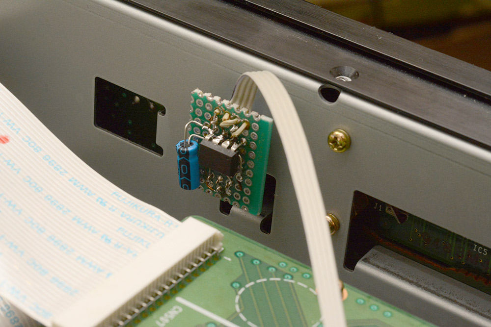
To the protoboard
The circuit was transferred to this offcut of protoboard.
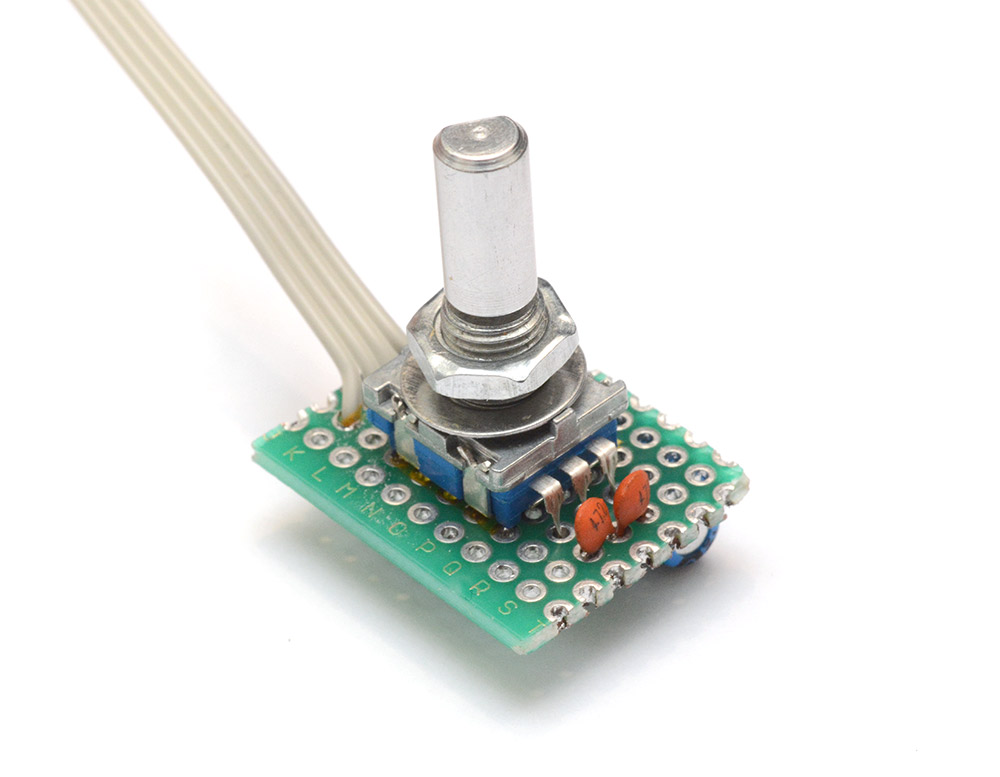
I probably should have gone for a bigger chunk, as few people would be proud of this soldering job. Part of the mess is because my ribbon cable comes from a reel that's older than I am, which is starting to perish, and partly because I should have re-ordered the wires before they hit the board so there didn't need to be so much crossing-over.
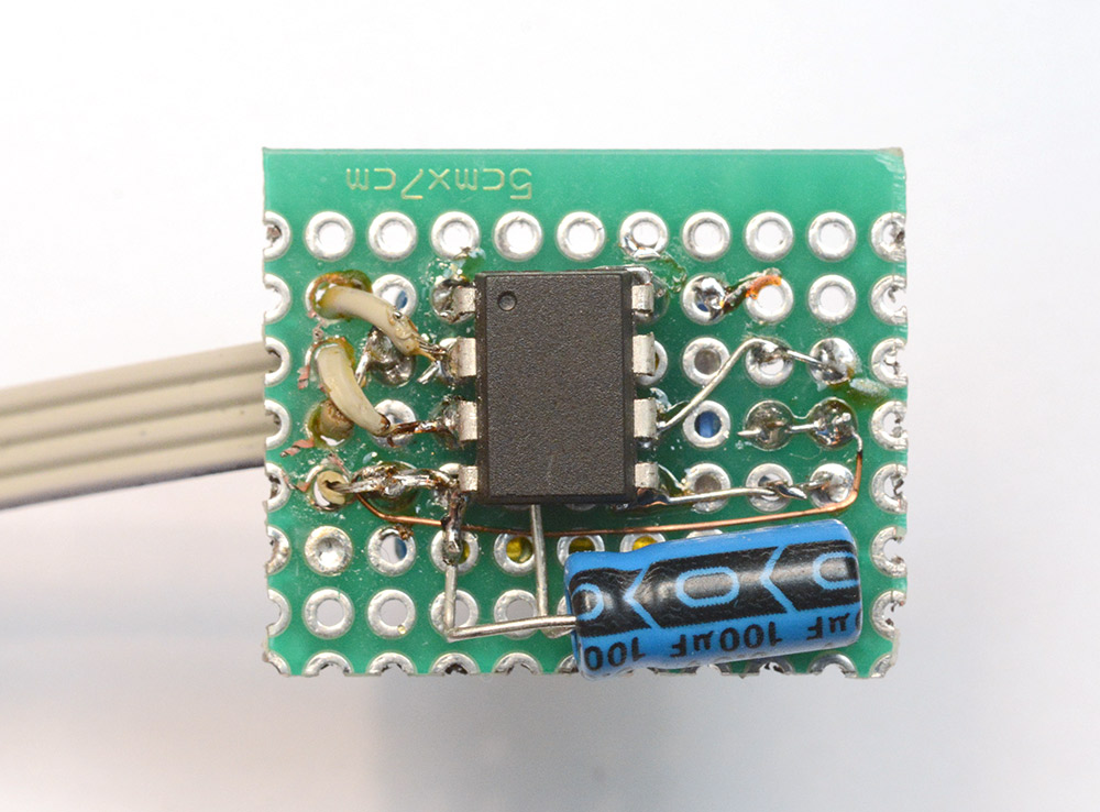
The chip is still reprogrammable using a test clip, as usual.
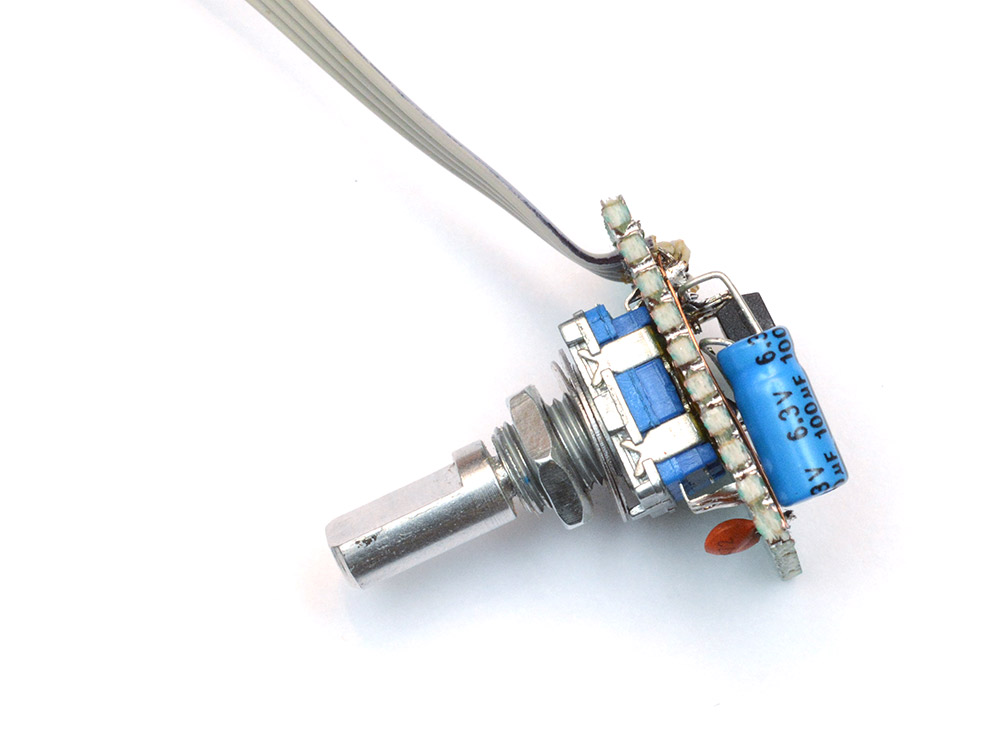
There is plenty of room in the case so this tiny circuit was possibly unnecessary. I should probably have checked the orientation the encoder needs to mount, so that the ribbon exited in a more sensible direction.
With the case back together, like all the best repairs, no-one would suspect it was ever apart.

The responsiveness, not entirely captured in that clip, is as good as I could hope for. Each detent is definitely one pulse on the output. Spinning very fast indeed does sometimes miss steps, but it's not clear if this is because the transitions are happening during the output pulse (where interrupts are disabled) or because the power supply is unstable under that load.
One more thing
Something that didn't occur to me until I got the case back together is that the cold startup time is significant. The 100uF capacitor charged from two 50K resistors has a time constant of about 6 seconds. So if it's been off for a while, it can take longer than the startup time of the synth for the knob to become responsive.One fix would be to go with a smaller capacitor, since I think we're quite safe to do that. But easier still is to remember that we haven't touched the button signal, which has its own stronger pullup. Making use of that to speed up the startup time is as easy as adding one wire from the button to the unused GPIO pin (PB2). It feeds into the power rails with its own ESD diodes and gives us a power boost, no other changes needed.
With this we have about double the power available in use, and when spinning really fast, any skipped steps seem to have vanished. Rock solid. And, since we wrote it with this in mind, the knob still works even if you spin it while holding the button down*. Excellent.
(*This is in fact the behaviour I was looking for at the beginning. Holding the button runs through the menu 10 at a time. Phew.)
The source code for this project is available on github.
Addendum
Regarding the disassembly, curiosity got the better of me and I dug even deeper. Each of the optimisation levels (-O2, -Os, etc) is a collection of flags corresponding to particular optimisations.We can see which optimisations are enabled with the following command:
avr-gcc -Os -Q --help=optimizers
-Os and -O2 had the smallest diff.
 $ diff <(avr-gcc -Os -Q --help=optimizers) <(avr-gcc -O2 -Q --help=optimizers)
2,4c2,4
<   -falign-jumps                               [disabled]
<   -falign-labels                              [disabled]
<   -falign-loops                               [enabled]
---
>   -falign-jumps                               [enabled]
>   -falign-labels                              [enabled]
>   -falign-loops                               [disabled]
43c43
<   -finline-functions                          [enabled]
---
>   -finline-functions                          [disabled]
72c72
<   -freorder-blocks                            [disabled]
---
>   -freorder-blocks                            [enabled]
106c106
<   -ftree-ch                                   [disabled]
---
>   -ftree-ch                                   [enabled]
119c119
<   -ftree-pre                                  [disabled]
---
>   -ftree-pre                                  [enabled]
It didn't take long to realize -ftree-ch was the flag responsible.
The loop itself is reversed by the compiler in order to use brne as an end condition. In the code generated by -Os, the loop counter is started one higher, and the first loop is skipped over by the jump.
In the GCC docs on optimisations they give a list of flags turned off when using -Os. This was in fact the first place I looked, without any luck, because -ftree-ch is not listed there. Further down the page, searching for it we find this:
-ftree-chPerform loop header copying on trees. This is beneficial since it increases effectiveness of code motion optimizations. It also saves one jump. This flag is enabled by default at -O and higher. It is not enabled for -Os, since it usually increases code size.
The general advice I've heard for AVR is to "always use -Os". I think I will stick to my own mantra, "always use assembly".