
Hydraulic Ram Revisited
2 Jun 2023I'm about to break my own record for how long it took me to write up a project. This journey began so long ago that it almost predates the existence of this site. Let's travel back in time all the way to 2008, the dawn of this project, and the start of a quest to water a garden.
The garden in question had a small river running along the bottom of it. If you wanted to water the garden with water from the stream, you'd have to awkwardly scramble down the bank, and then carry a full watering can back up with you, as illustrated in the following diagram.
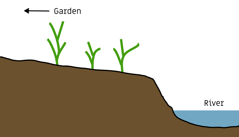
So the original project was simple, to make it easy to fill up a watering can from a stream only a few metres away.
The first pump
In the course of human history, we've come up with quite a few ways to move water about. The number of options is somewhat daunting.Perhaps the simplest and fastest solution would be a bucket on a string.
We've got some additional requirements here though, first that it has to be easy to use, especially for someone with a bad back. Second, and perhaps the most restrictive part, is that it has to "look nice".
I decided to build a hand pump.
Having double-checked that a traditional-looking hand pump met the criteria for looking "nice" I set out to build one from a collection of PVC pipe fittings. I only have this one picture of it, taken a few years after it was decommissioned:
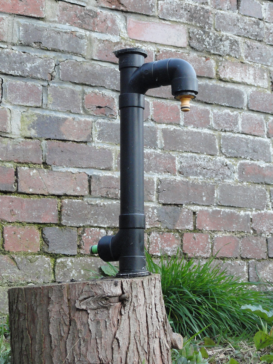
Inside the pump, there are two check valves, one at the base and one in the sliding piston. They were epoxied in place using the very same tube of JB Weld I used to build my watercooled PC. The valves came out of a ready-made 15mm double check valve, which you can buy for about £2. These are fitted to every household water supply as a means to stop backflow into the system.
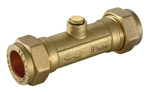
If you dismantle one of these, you'll find two plastic, spring-loaded check valves inside. The spring is remarkably strong – one of the first things I tried was blowing through the valve with my breath, and found I couldn't in either direction. I further pulled these apart to remove the springs, and then they behaved as I expected.
I'd consider the pump a partial success. It technically pumped water. When choosing the bore and stroke I made a wild guess, and overshot somewhat, which means quite a lot of force was needed to lift the water. I compensated by fitting a longer handle, but the forces involved put too much stress on the bracket at the top, which soon broke. I don't know what became of the handle, but I know that the pump didn't see much actual use.
The other problem is that I didn't understand how traditional hand pumps are supposed to work. I spent a long time fitting and fiddling with O-rings trying to keep things perfectly sealed. The pump will only work if it's primed; there needs to be water in the piston and the feed pipe for it to create suction. I had hoped to seal the system well enough, fitting another checkvalve at the water intake, that it would be permanently primed, ready to go even after months of inactivity.
But traditional water pumps obviously didn't work this way. Funny enough, it was only when I watched My Neighbour Totoro that I first saw a depiction of priming a hand pump. They fetch a bucket of water from the stream, and pour it into the top of the pump to begin, then keep pumping until the water comes out clean.
I learnt a lot from building this, but perhaps the most valuable lesson is that even with a fully functioning pump, filling a whole watering can by hand takes a lot more exertion than my client had anticipated. We have a whole river available, surely there's a way to lift water that doesn't wear us out?
The Archimedes' Screw
I should probably clarify that the section of river at the bottom of the garden was quite short. Although there was a reasonable flow rate, the altitude drop across the width of the garden was virtually nil. This rules out almost all water-powered water pumps except for one.In 2010 I built a prototype Archimedes' screw and I'm really sad to say I can't find any pictures or video of it. My design was not strictly speaking an Archimedes' screw, but closer to a coil pump.
With an Archimedes' screw you have a significant sliding surface that both needs to be sealed and adds friction.
Instead, I took a length of PVC pipe, and wrapped flexible tubing around the outside, to form a coil. Naturally, I made it double threaded. Through the middle of the PVC tube I fitted an aluminium rod, which was then mounted into a pivot, and the top end just rested on a u-shaped support. The whole thing rotated with very little friction. To compensate for the lack of pictures, here's a quick render:
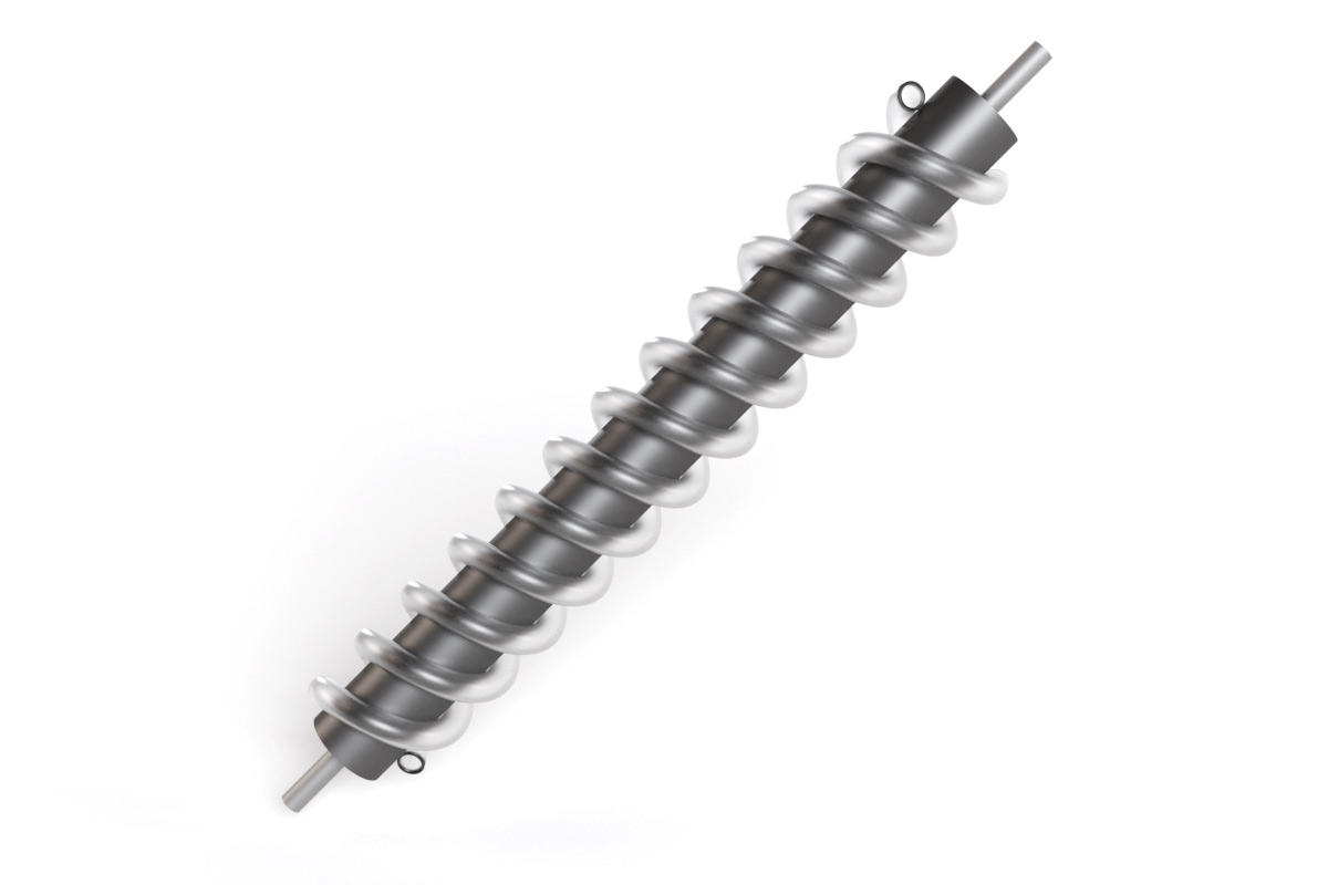
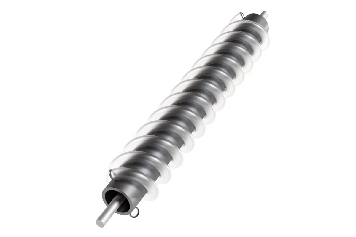
The PVC was 2 inches diameter, the flexible tube was only 10mm, and the whole thing was longer than in the render. I'd planned to build it all bigger if the prototype worked. But even this mini version had a certain satisfaction to it, you could rotate it as slowly as you liked, pumping a tiny amount of water, but always to the same height.
I make a big deal about it being low friction and constant pressure because the idea was to have it self-powered.
It's possible to make a coil pump with a paddle wheel in the water, perfect for situations with flowrate but no appreciable drop. There is a video of such a coil pump working on youtube, here's a screenshot:
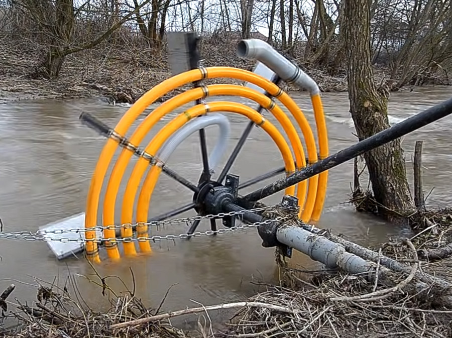
But this necessitates either a rotating seal, or in our case, some kind of transmission between the inclined screw and the horizontal paddle wheel.
Something that didn't occur to me at the time, is that you can build a coil pump without a rotating seal, but still with all the turns at the bottom. I much later discovered this page with a history of coil pumps, and this diagram caught my attention:
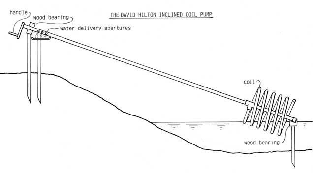
There's something quite pleasing about that design, and I most likely would have attempted it, had I seen it back then. It can even be simplified further by making the coil around a sealed drum, so the whole coil floats in the water, which eliminates the lower bearing and automatically adjusts to the water level.
Back to my Archimedes's screw. Having ruled out paddle-power, instead, I fitted a small DC motor to the top of the screw. If there were electrical power available, sure, we could have just used an electric pump. It's about 30 metres from the river bank to the house, so this was always an option. But the plan was to use solar power. I bought a small 8W photovoltaic cell designed to go on the back shelf of a car. Wiring this up to the DC motor produced rotation – perfect! Even if the sun goes behind a cloud, the flow rate reduces but doesn't stop. So long as we add a reservoir at the top, it can pump as slow as we like and still eventually fill the tank.
Unfortunately, the whole concept was rejected as being too much of a "contraption". Note the earlier requirements about it needing to "look nice". And realistically, we'd need to do a fair bit of work around both the outlet and the inlet, to stop it getting clogged and to make the base of it stay at the waterline.
The Submersible Solar Pump
While the Archimedes' screw was rejected, and the paddle wheel was rejected, to my surprise the solar panel was met with approval. A solar-powered electric pump would meet the bill.Left over from my watercooled PC build, I had a number of different electric pumps of varying sizes. One of them was a submersible caravan pump, that ran on 12V and was far too powerful for the PC build. I wrapped it in a filter and chucked it in the river, it certainly had enough pressure to reach the garden. The problem is that there was no way it would run from the puny solar panel.
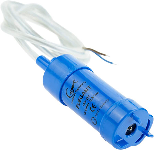
What I would really have liked is a small, self-contained submersible pump that delivered constant pressure but reduced flow as the available power dropped. The mind boggles at the number of different types of water pumps out there, and perhaps there's something available that would work, but for now (and by "now" I mean 14 years ago) the simplest way to get this caravan pump to work with this solar panel is to use a battery.
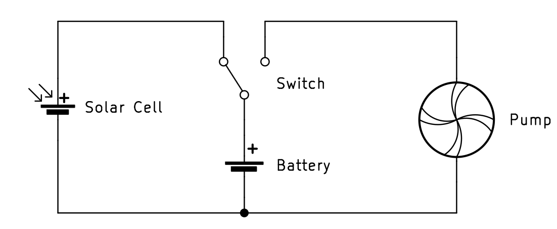
I bought a small lead-acid 12V battery and fitted it in a box with a DPDT switch. In one position, the battery drives the pump. In the other position, the battery is connected to the solar panel, which trickle charges it.
The system worked! Again, I wish I had some pictures to share. My only regret was that the battery and switch was a little too complicated. I checked in a few weeks later and realised I hadn't explained properly ("It was a very sunny day, so I left it pumping") but in the end it did see enough use to justify all this effort. The solar panel was mounted to the top of a wooden trellis and looked quite smart.
As far as I know, it was still working when they moved house a couple of years later.
Enter the Hydraulic Ram
A new year, a new house, a new garden and a new stream.In 2012 I was delighted to be asked to produce the same or similar solution for watering the garden from a stream. Validation! This time the stream was much lower flowrate, but a lot longer and dropped almost two metres from one end of the garden to the other.
"Forget electric pumps," I said, "I'm building a hydraulic ram!"
A hydraulic ram pump is what I had originally wanted to build, if the conditions had been right in the previous setup. Let's talk a little about why I like them so much.
The pump uses the flow of water to pump water. It's powered by a small pressure differential, possibly as low as 50cm, and has a low-flow, high-pressure outlet that can be more than ten times the input pressure. The input pressure is usually achieved by just dropping a length of pipe along the bed of a stream.
Aside from being very simple, very reliable, and self-powered in an almost magical way, the main reason I like them is that hydraulic ram pumps are directly analogous to electrical boost converters.
There is much to be said about the analogy between fluid dynamics and electricity. Current is flow rate, voltage is pressure. Some people dislike it, but not for the reasons you might think. While the analogy can be surprisingly accurate, the best argument against using it to teach electronics is that most students don't have an in-depth knowledge of fluid dynamics! I'm not saying that I do, but I do like the analogy, and hydraulic manifestations of electrical circuits are particularly pleasing. From my perspective, the boost converter is a good way to explain how hydraulic rams work.
A boost converter looks like this:
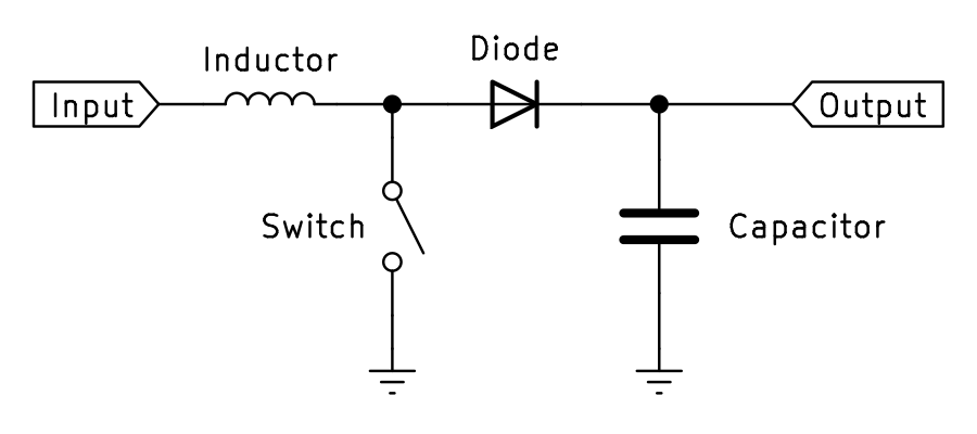
When the switch is closed, current starts to flow through the inductor to ground. When the switch is opened, the inductor creates a voltage spike as the electric field collapses, which goes through the diode and into the capacitor.
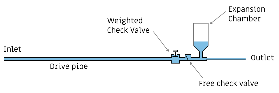
In the hydraulic ram pump, the inductor is the drive pipe, the free check valve is the diode, and the expansion chamber is the capacitor. In a boost converter, the switch is normally a mosfet controlled by an integrated circuit that monitors the output voltage. With the ram pump, the weighted check valve serves this purpose, as a kind of self-regulating switch.
Just as there is an optimal size inductor, the length and diameter of the drive pipe is important to get right. The rigidity also matters, I went with thick PVC pipe which isn't as efficient as a steel pipe, but it's cheaper and much easier to work with.
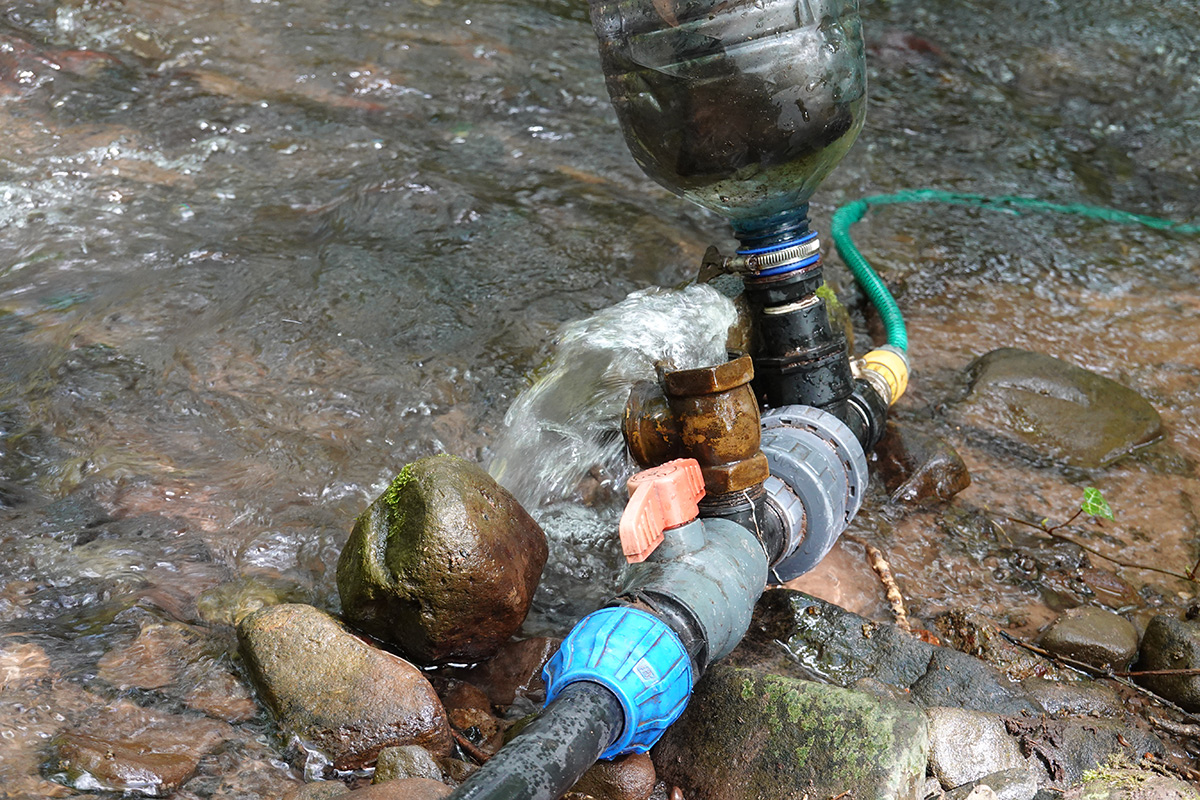
The pump was built entirely from off-the-shelf parts. Even the weighted check valve was an off-the-shelf part, a brass swing valve. For the expansion chamber I used a 5-litre water bottle, and stuffed an inner tube inside of it. Without this, over time the air in the expansion chamber can dissolve into the water, and eventually disappear entirely. I remember this being a little tricky to install, you have to stuff the inner tube in the bottle, holding on to the valve, so it can be inflated inside.
The available stream was well over 50 metres long, dropping about two metres across the length of it. To make the best use of this, given the requirements on the aspect ratio of the drive pipe, I built a stand pipe. This lets us increase the input pressure without affecting the drive pipe.
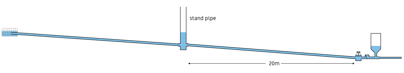
The PVC pipe I bought was I think 50m long, and for my diameter pipe the calculations suggested a drive pipe length of about 20m. The remainder of the pipe stretches further up the stream, and at the inlet a crude filter stops muck getting in it. The stand pipe was built from 4-inch PVC drain pipe, and the fittings were extremely crude. Ordinary tank connectors wouldn't work on the round drain pipe, so I simply solved the problem with silicone sealant. In retrospect, I should have used some square-profile pipe as the stand pipe (or an actual tank).
In some sense, the stand pipe functions as an input capacitor, although being open to the atmosphere I suppose adds a zener diode to the analogy. It might have been enough to instead add a T-connector to the pipe and use the same diameter for the stand pipe. While this wouldn't have been as good from a fluid dynamics perspective, it would have greatly simplified construction.
Enough pontification. The hydraulic ram pump worked beautifully. Nothing really compares to seeing it pulse away indefinitely. I fitted a regular hose pipe to the outlet, and carried it right up the garden. I fitted a spray nozzle onto the end of it, and the result was a self-powered fountain. I threw the hose pipe over a tree, about 10 metres above the contraption, and water continued to pump as if by magic.
You can probably imagine my regret at not taking any pictures or videos of it.
The fate of the ram
The plan had always been to install the pump at one end of the stream, but for convenience I fitted it a little further up. In this "temporary" location it remained for some time. There weren't any foundations or attachments for most of it, apart from a few rocks layered on the pipe in places. The stand pipe was tied to a tree.If I had known it would stay there I'd have secured it all much more thoroughly.
I considered the pump an astounding success. I never doubted it would work. As for my client, I obviously overestimated their enthusiasm, as the following year it was casually remarked that the pump "stopped working at some point". There apparently was a storm.
When I visited the site, the pump was gone. The stand pipe was still attached to the tree, but the dodgy pipe attachments had broken off. Quite a way downstream I finally found the pump, wedged in with fallen tree branches, with the drive pipe coiled up (the stiff pipe coils at about 3m diameter).
I didn't have time to reinstall the pump that day, as it clearly needed securing properly, so I lifted it up onto the bank and left it there.
And there it remained for about a decade.
The ram revisited
With the preamble now concluded, let's gear up for the main event.In this the year 2023 I revisited the site. I hadn't planned to search for the pump, but curiosity got the better of me.
Poking around with my boot, I found some buried pipe.
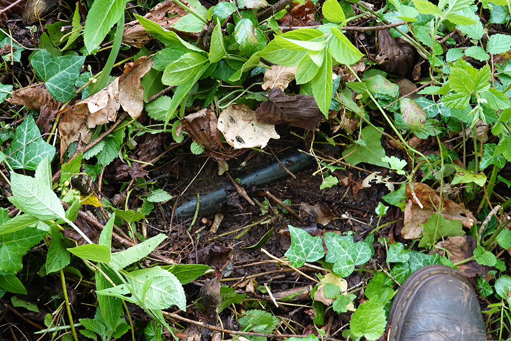
It's surprising just how deeply buried the pipe was for the most part. Ten seasons of brambles rising and falling, their corpses cascading on the PVC.
I eventually found the end of it.
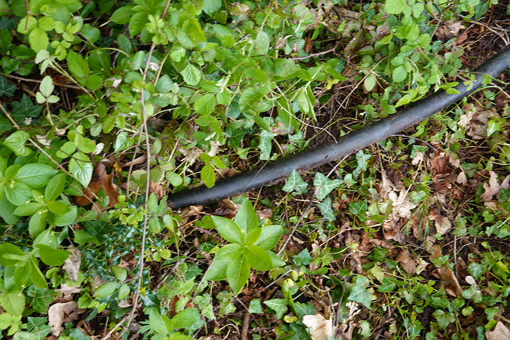
Then I eventually found the other end of it.
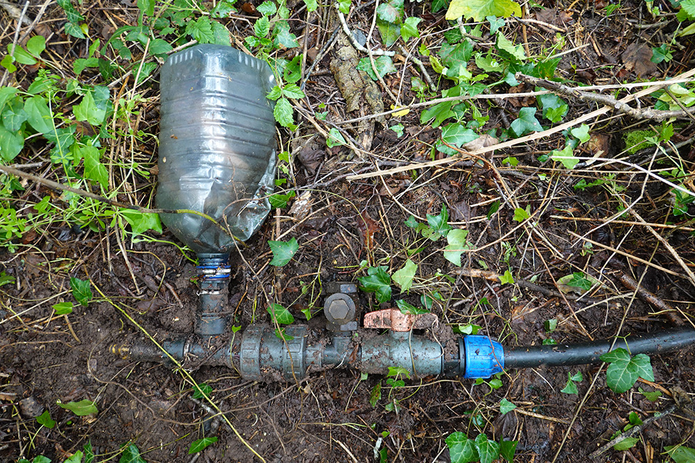
There she is, the pump! the pump! That soil will wash right off I tell ya.
I couldn't simply pull everything free, I had to manually un-bury the pipe for most of the length.
I wasn't deterred, I felt a lot like an adventurer digging for buried treasure. And what we found is a magic item, after all.
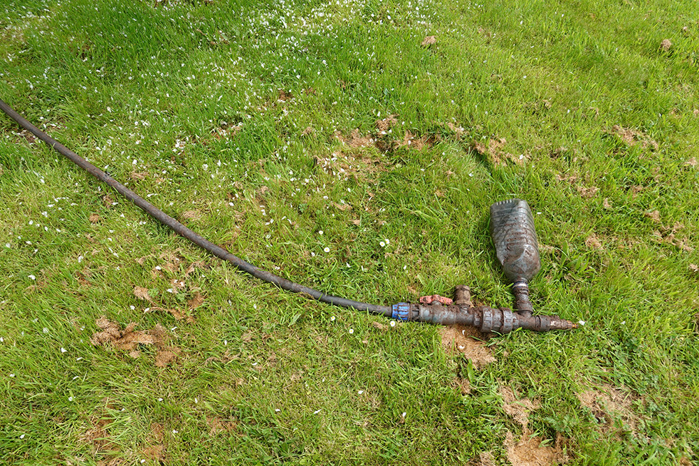
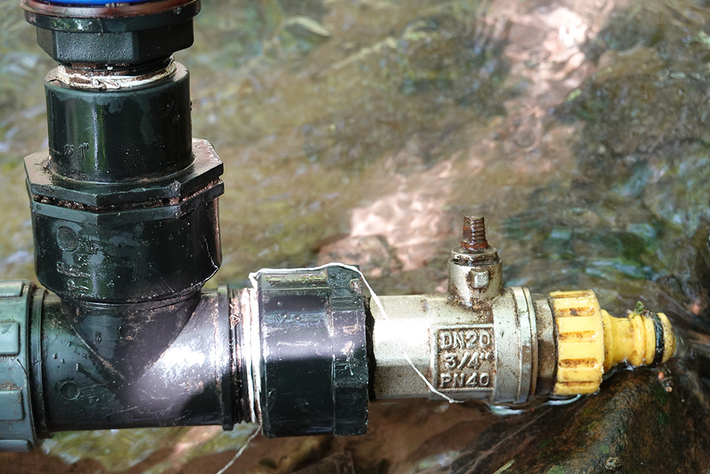
Everything appears to be intact. The only missing part is the valve handle on the outlet. The outlet valve isn't strictly necessary, but it helps to start the pump if you don't have an outlet hose attached (with no back-pressure, the weighted check valve will stay closed).
Our immediate concern was whether chucking the thing back in the river would fire it up again. It turned out there was a significant amount of mud inside the drive pipe. I draped it in the stream, with maybe two feet of height from one end to the other. Barely a trickle came through. I unscrewed the blue hose connector and with a little agitation, a 6-inch cylinder of mud plopped out. The drive pipe was cleared.
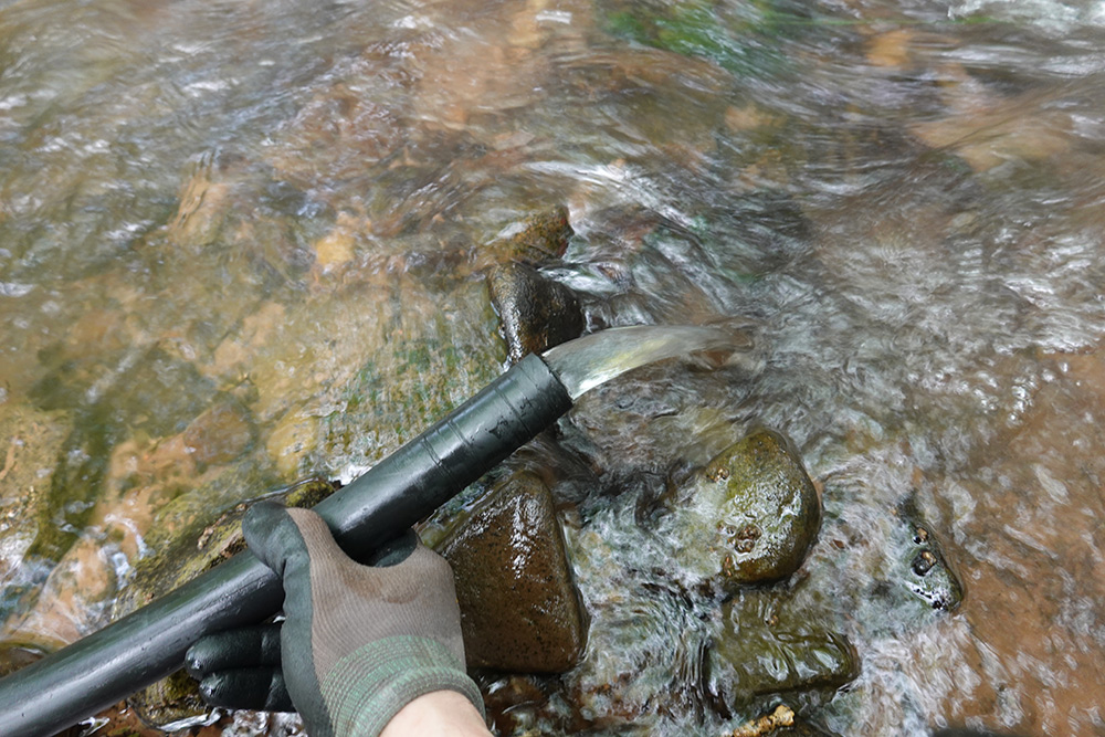
I feel a little like a child again, playing in the stream. If you stick your hand over the end of the pipe, you can feel the water-hammer effect, that is the heart of the ram pump.
My theory is that once the pipe and pump disconnected from the stand pipe, they flowed downstream and at that point the mud got into it. From what I can tell, the original inlet remained clear, because there's no mud in the stand pipe. However, the original inlet filter is nowhere to be found, it must have been washed away.
Rinsing off the pump, we plugged it back in, and – life!
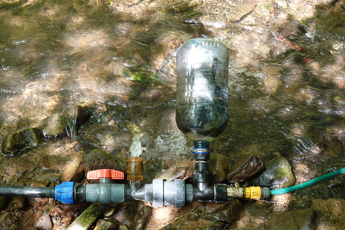
The astonishing part is that the 5-litre PET bottle survived. I think being buried kept it away from the harmful UV rays. With a crackling noise, the crumpled dents re-inflated as the pump built up pressure.
Without the stand pipe, it's running from a tiny input pressure, much less than a metre. As such, the weighted check valve pulsates very sedately. Originally it had about 1.5m of head, and would pulse about once a second.
Even at this low input pressure, it had no problem pumping through the hosepipe I threw over the nearest tree branch, about four metres up.

If I were to raise it higher or carry the hosepipe up the garden, the flowrate would drop but the pressure would increase to compensate. It's unclear what the maximum pressure would be.
To bring this article into the 21st century, here are some embedded videos of it pumping.
In this one you can clearly see the expansion tank water level rise at the end of the pulse:
It does bring some satisfaction to see it working, and to finally get video evidence that it worked. The remaining question is what to do with it now.
One option would be to install it properly, fix the stand pipe, replace the inlet filter and secure everything so it won't be washed downstream. It could potentially pump for years, even with the complete neglect it's likely to receive.
The other option is to throw it back on the bank and come back to it in another ten years.
Moving parts
Building the ram pump, and finding that it worked so well, especially after the journey through different water pump approaches, had an effect on me. For some reason, one idea I kept returning to was whether it would be possible to build a hydraulic ram pump with no moving parts.I eventually posted a somewhat nonsensical concept about water flowing uphill, a hydraulic ram from siphons and tesla valves, the kind of drivel spouted when one has too many ideas at once.
The concept's well overdue for an update, and I can now confirm that there is such a version of the ram pump with no moving parts, one that doesn't depend on tesla valves or siphons. In fact, it's a lot simpler than that.
There's a type of pump with no moving parts called an airlift pump. Compressed air is used to (somewhat inefficiently) lift water. It is undeniably, unremarkably a water pump with no moving parts.
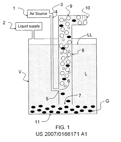
What I was less aware of is that an airlift pump can function in reverse. Water falls down a column, pulling in air and and compressing it. It's called a "trompe" and the device saw widespread use before the invention of modern compressors.
While Wikipedia is undoubtedly better than it was ten years ago, this category of devices is still an absolute mess with conflicting and incorrect information. I found the French Wikipedia page on the trompe to be much more informative.
Here's a sketch of a Trompe from 1797 by the hand of Giovanni Venturi himself.
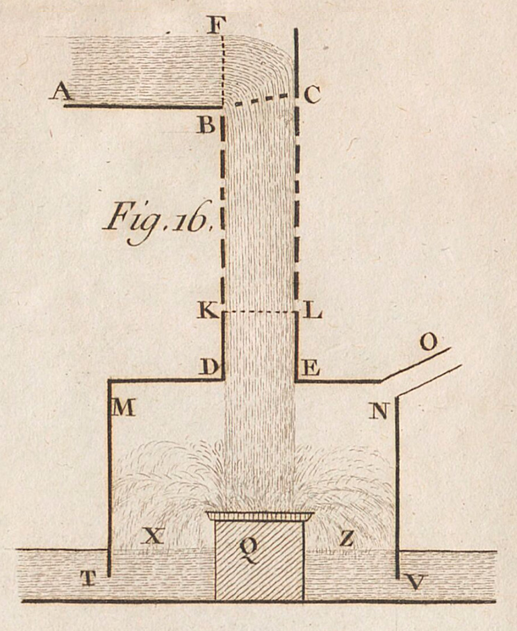
The venturi effect sucks in air as the water is falling, it's then compressed and output through O, with the waste water leaving through T and V.
Trompes were mostly used for powering furnaces, but some enormous ones were built. It would be remiss of me not to link to this site about the Ragged Chute facility in Canada. Compressed air was needed to power mining equipment, so a vast water-powered air compressor was "invented" in 1910.
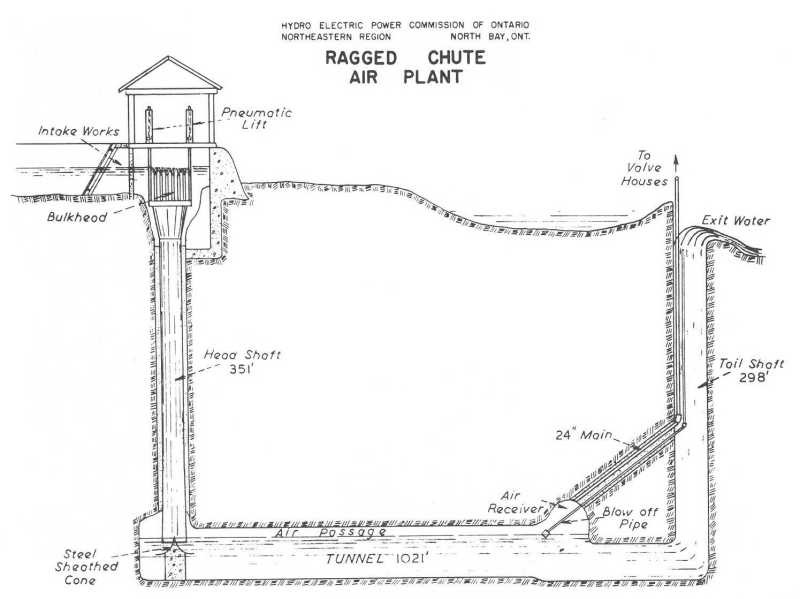
Despite what the piclist site says, it seems the plant was closed in 1981. Its closure is more to do with the closing of the mines than anything else. On youtube someone has uploaded VHS footage of the facility, where you can see the pressure-relief blowoff creating a huge geyser.
With the existence of water-powered air compressors not in question, and the existence of air-powered water pumps likewise accepted, the route to a water-powered water pump with no moving parts is obvious. In fact, the two devices can apparently be combined into something described as a "pulser pump".
Information comes almost entirely from one individual named Brian White. From this site there are links to youtube videos of the pump working. In the comments there are a few useful (and a few not so useful) discussions about variations on the pulser pump.
When compared to the hydraulic ram, a pulser pump is less efficient, and significantly harder to install – even if the total input head difference doesn't need to be much, the need for a large vertical drop for the trompe means a significant amount of digging.
Still, I feel reassured in the knowledge that a no-moving-parts powered-by-water water pump exists.