
Headphone Amps
27 Jun 2016Progress: Complete
Headphone amps are a pretty simple electronics project. In fact I always thought they were a bit pointless, most audio driver chips on a laptop or CD/MP3 player are good enough. I never really considered making one.
Then one day I got hold of a DAP meter (Does-Area-Product meter) and tore it to bits.
The entire thing was gorgeous, filled with high quality parts built in maintainable, repairable ways (almost everything socketed) and it was probably hand built in small numbers. Superb quality. State of the art for early 90s. The main processor was an Intel 80C32 which ran code stored on a UV-eraseable 27C512 eprom. There were temperature, humidity and pressure sensors. There was an extremely well filtered linear-regulated power supply. And of course, there was the high-voltage section, which had a bunch of chips working at the higher voltage and fed the readings back via VFCs and optocouplers. The high-voltage connectors were delicious, knurled coaxial sockets with screw-tops on little bath chains.
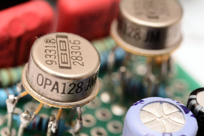
But the most curious looking parts were these interesting chips in metal cans – the TO-99 package. The Burr-Brown logo was etched on top, and the part number, printed around the rim, was OPA128JM: op-amps. Not just any op-amps, these were serious op-amps. They sold for a huge amount of money when they came out. Electrometer-grade.
When faced with seriously expensive and obscure amplifiers, there is only one course of action. Build a ludicrous audio amp. The qualities that make these OPA128s so expensive have nothing to do with their audio qualities, but, they can't hurt, can they?
So I built me a headphone amp.
The Circuit
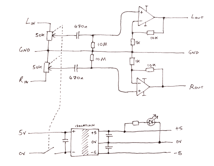
I put both amps into a standard non-inverting amplifier configuration at a fixed gain of about 10, with the volume control varying the input attenuation. This has a couple of benefits over directly varying the gain, depending on the op-amp characteristics. Particularly at low gain many op-amps have troubles.A high pass filter cuts out the DC. Some people say the type of capacitors you use has a big effect on the sound quality. I used some special red ones I found in the DAP meter, I don't know what they are, (possibly polypropylene film?) but they're probably better than cheap ceramic things. The other thing to worry about is the power supply. Well, the way these amps were powered in their original situation was via an isolated DC-DC converter. This tiny black box sat across the high-voltage line and took +15V in, outputting an isolated +/-15V supply on the other side. Very nifty.
The use of switched-mode power supplies in audio circuits can cause some audiophiles to swoon. However, if it was good enough for the DAP meter and its electrometer-grade application, I'm sure it's good enough for audio. I also re-used the exact same capacitors it had around it. The benefit of the isolated DC-DC converter is that we can power it from a single supply, and that there's zero risk of ground loops developing if it's powered from a different source to the audio.
At this point I should probably explain that my headphones are labelled AKG K702, 68Ω. And I was driving them from my fairly boring laptop. Picture my surprise, then, when the headphone amp gave a noticeable improvement in sound quality. I raised my eyebrows, and I even said, "oh!".
The improvement is basically just because of the driving capabilities, 68Ω is fairly high for headphones. Where the laptop was at the limit of what it could drive, the OPA128s are rated to something like 500mA each, so were well inside their comfort zone.
There is a good reason I don't have any pictures of this first headphone amp, though. It was quite susceptible to noise, particularly if sitting next to the laptop power supplies, and my solution was to wrap it in aluminium foil for shielding. It was rather ugly to say the least.
One channel was worse than the other. Actually I had a bit of fun experimenting with shielding, I found that if it isn't grounded it's almost entirely pointless. It will only act as a Faraday cage if it completely surrounds the circuit, which is very difficult if you have a bunch of cables going in and out. Whereas, a single piece of metal between the noise source and the amplifier will cut out 90% of it if it's grounded. You can hear the noise vanish as you touch the ground lead to it. The whole experience of actually playing with this taught me a lot more about shielding than all the theory I'd experienced until then.
The DC-DC converter is supposed to take 15V in and spit out a dual +/-15V supply. But the most convenient power source is a USB cable that only delivers 5V. This is actually suitable for most applications, the amp will output up to about a volt away from its power rails, and it's rare that you need more than 8 volts peak-to-peak. However, one channel would clip at normal listening volumes. Not ideal. To combat this I added an additional switched mode supply, this time a boost converter to step the 5 volts up to 15 volts before going to the isolating DC-DC converter. The problem was solved, but in a rather ugly way.
Wrapped in tinfoil, I used it for a few months.
The next attempt
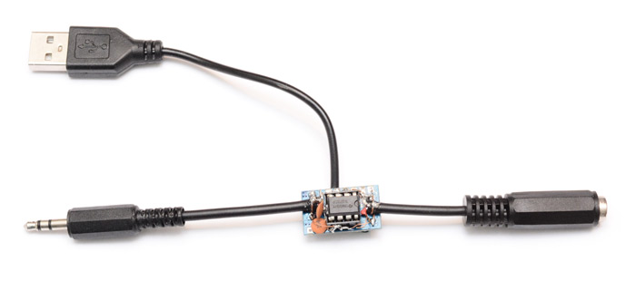
The biggest problem with it was the inconvenience. It improved the sound sufficiently for me to be annoyed not to use it, but a ball of tinfoil with cables sticking out is about the least practical peripheral you can imagine. Since the improvement was mostly due to driving capabilities, surely a simple, cheap op-amp system would work just as well? Perhaps I could build a tiny headphone amp, that went inline with the cable.This idea seemed good. There is a USB port right next to the headphone port on my laptop. It could connect to both at the same time.
I was pretty pleased to find a tiny switched-mode power supply module on ebay that took 5V in and output dual, +/-15V. That'd be perfect. Not isolating, but it shouldn't matter - you'd hope the audio ground would be at the same potential as the USB ground.
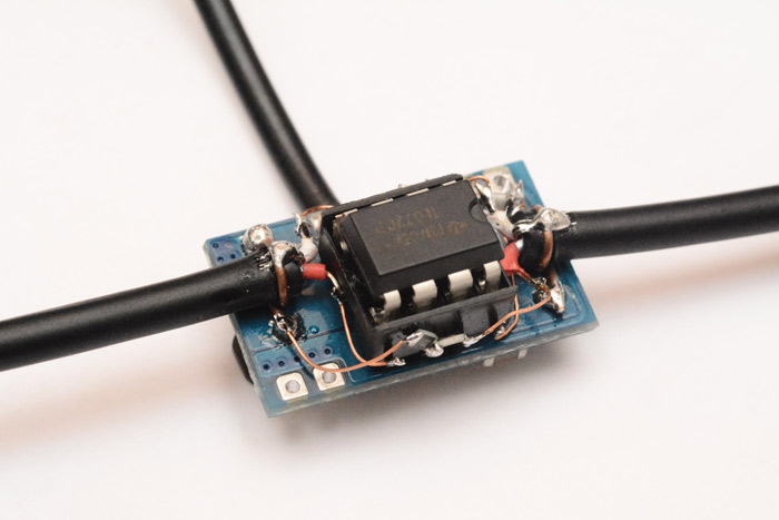
I built up the circuit on the back of the step-up module, using tiny parts where possible but socketing the op-amp so it could be switched for a better one if needed.
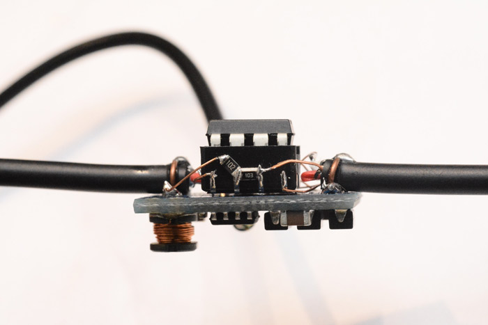
The cables were attached by scraping back the solder resist on the ground plane to expose the copper, then soldering wires to it and wrapping them tightly around the cables. This worked really well.
However the amp was terrible. After a few hours I eventually gave up with this idea. It was noisy and uneven. It may have been poorly wired, or shortcircuited as a result of the cramped construction. I added more capacitors, rewired it a few times but never got anywhere near a result that could be described as improving the sound. I even dropped in a pin-compatible fancy burr-brown op-amp, which sounded different, but not better. Shame really, because this had potential.
Attempt numero trois
That was last year. This is now.Well the obvious way of making the fantastic ball of aluminium more portable is to stick it in a metal enclosure. This would shield it from the EM noise and the physical trauma. I ordered one.
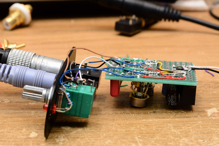
Unwrapping the foil, this is what we find inside.
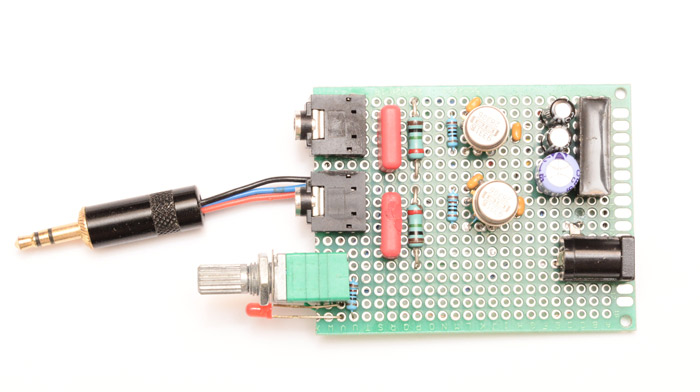
It could have been built much smaller but I remember that when I put it together I didn't know if the opamps even worked. The additional 3.5mm connector is so that the input could take from a headphone extension cable, which was sometimes more convenient. The red parts are the capacitors of the high-pass filter, followed by the large, 2% 1Meg resistors.
Each op-amp has a tantalum 0.1uF cap on each power rail, and two resistors (one crosses underneath) to form the non-inverting 10x gain circuit. The potted black box is the isolating DC-DC converter, with capacitors on the input and two outputs. Lastly is the barrel jack, standard 5.5 by 2.1mm.
The potentiometer is a switched stereo pot, and the LED indicates it's turned on. Both of these were later additions. The LED mostly because it's annoyingly easy to leave it switched on overnight.
The underneath is a glorious mess.
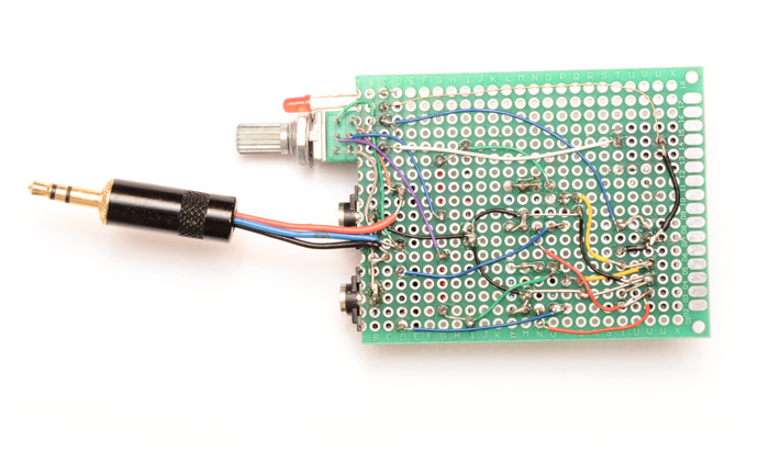
I remember having great difficulty with desoldering the op-amps. Unlike almost everything else in the DAP meter, they were not socketed, and I guess the circuit was wave soldered, because the through mount parts all had their legs bent over underneath so they were secure before soldering. The op-amps each had eight gold legs which needed bending back while the solder was molten.
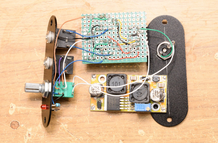
The case that I'd bought was anodized aluminium. I made sure it was big enough for the circuit, even including the extra boost converter. But to be on the safe side I moved some of the components closer together before cutting the protoboard. This involved swapping the big resistors for little 10Meg ones (higher resistance = lower cutoff frequency = better bass + less phase distortion), and also in the process I noticed that one of the capacitors was wired oppositely to the other. I figured these were not polarized capacitors, but for symmetry I turned one around.
I laid out, centre-punched and then drilled the holes to mount the input, output, volume knob and LED. Here's confirmation that it would all fit.
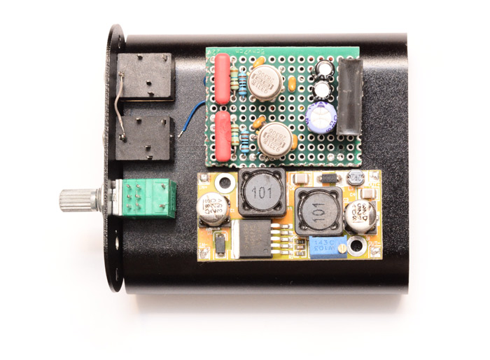
The boost converter is actually a SEPIC module that includes both a boost and a buck stage. You can feed it pretty much any voltage, and it spits out whatever voltage you like. Useful. Possibly overkill.
Next we wire it up and give it a test, nominally to be sure that nothing is broken. But...
Astonishing! It sounds even better than before, and this is without any shielding! The noise floor plummeted. The channels are almost exactly equal (the limiting factor is now the balance of the stereo pot). And the clipping has disappeared, it goes louder than I'd ever want without needing the boost converter. How did this happen?
The only things I changed, as far as I'm aware, are: one capacitor was turned around, the 1meg resistors were swapped for smaller 10meg ones, and the connectors were changed for panel-mountable ones. And I'm possibly using a different headphone lead.
To be honest, this annoyingly unexplainable improvement means the resulting circuit does not even need an enclosure. But let's finish it up anyway.
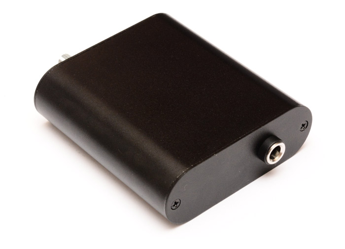
I mounted the barrel jack and wired it directly to the isolated DC-DC converter, via the switch, but just to be sure, there's easily enough room in there now that we could add the boost converter if we needed it.
A closed, completed, crazy quality headphone amp.
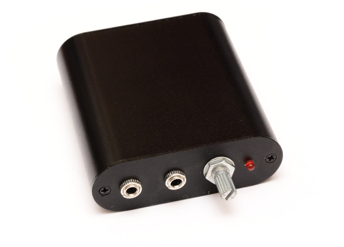
Needs a decent knob though. And labels.