
Hardware Reverse Oscilloscope
18 Jul 2015Progress: Complete
The Reverse Oscilloscope is my beloved little synthesizer, named as such since it originally revolved around hand-drawing waveforms.
This is just a bit of fun. If I actually wanted to build a standalone reverse oscilloscope I'd probably go with a little touch screen. But as I mentioned at the end of the reverse oscilloscope page, the temptation to build an analogue reverse oscilloscope is mighty. And I promised I'd do it next time I found a bunch of slide pots. Well, I found a bunch of slide pots, so to hell with it, let's do it!
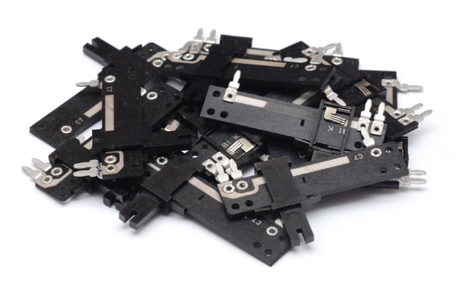
Unfortunately they're 1K, 20mm travel and there's only 15 of them (16 would make life easier). But they'll do.
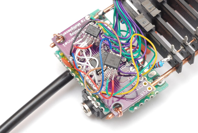
The chip we need to cycle through their values is called an analogue multiplexer. It takes a binary input on a few pins and multiplexes an analogue voltage between one and many pins. I found this 16 channel analog multiplexer (74HC4067) on a breakout board for £1.51 including shipping.
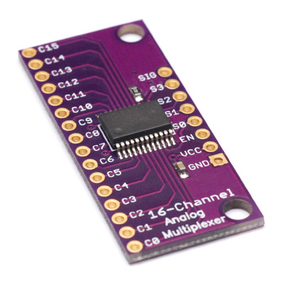
To control it we send it 4 bit parallel data. You can get binary counter chips of course, which would just need to be clocked at the speed corresponding to the pitch of the note. Since I plan to deploy an ATtiny running my midi synth to control that pitch, we may as well do the counting/parallel output on it too, so long as we have enough pins. In addition, bizarrely, those binary counter ICs are more expensive than an ATtiny85. Supply and demand I suppose.
Most waves are symmetrical, so I suppose we need an even number of sliders. Since 16 is out, 14 is probably the number to go for.
On second thoughts, I think I'll chuck an ATtiny13 in the mix. They were only 30p each after all. It can be the binary counter, counting to 14 and then resetting, clocked by both the rising and falling edges of its input. This means we can use our square-wave midi synth in unmodified form to drive it. All we have to do is kick it up a couple of octaves.
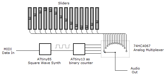
(Aside - is that how you draw a single-pole-14-throw switch? Except it's supposed to be 16 throw, isn't it, err... no one will notice...)
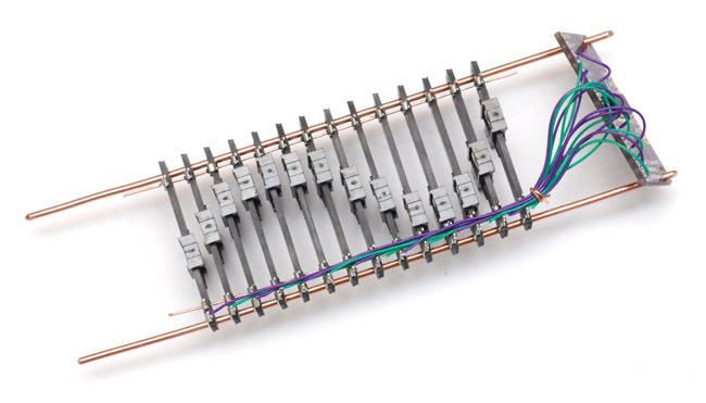
So, first thing to think about is how to mount the sliders. Unfortunately the pitch of their legs was different to the standard .1" of protoboard, so I had to think about this for a while. They all have mounting holes through them, so I ordered some M2 standoff bolts that could slot through and make a nice rigid structure. I thought this was easier than hand-making 28 parts on the lathe. But the multiplexer arrived in the post before the bolts, and I got impatient and took a different route: I found some stiff 1.8mm diameter copper wire to thread them on (the holes are about 1.75mm, so it's real snug).
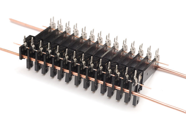
Each leg, where it's connected to the body, is pressed in a way that leaves a hole, so I threaded more wire through there to link the rails without really thinking about it - this was a mistake as I'll explain in a mo. All the signal wires were soldered and neatly bundled along one side, linking to the multiplexer board.
Programming the ATtiny13 took all of about 2 minutes, and for the ATtiny85 I only had to change two lines, to set the base octave.
It didn't work. The multiplexer worked, the ATtiny chips definitely worked. But no reverse 'scoping. When I wiggled the sliders, it would change the sound output, which suggested a loose connection. The most common (only?) failure mode of a potentiometer is the brushes, and I spent ages playing with them trying to fix it. Of course, having soldered it together, it was particularly difficult to get at them. Much scientific investigation later, I finally found that the legs were no longer connected to the traces.
The reason was to do with the way I'd soldered the rails to them, sliding it through the already present hole in the contact. That's where they were pressed/riveted on. I'd let the solder wick into the join and it gave a great mechanical link but in the process broke the original contact. The conductive traces are totally solderphobic, and I reckon the heat had softened the plastic, and reduced the pressure on the join.
Luckily, with that in mind, the solution was as simple as going over each one with a pair of pliers and giving it a good crimp. Ahoy, success!
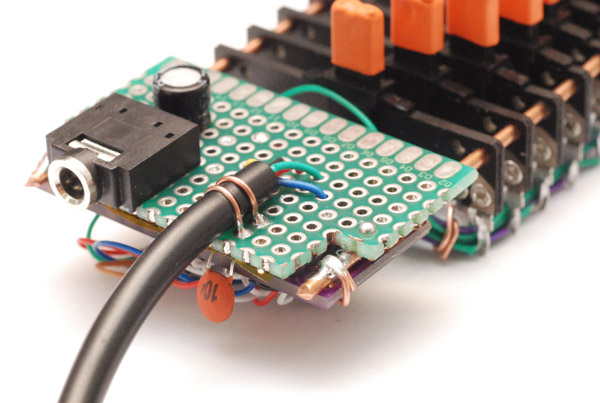
Finishing up, I did my usual thing, free soldering all the parts together floating over the multiplexer board, then realizing we need some way to attach the cables securely, and having to attach a piece of protoboard after all. It's soldered to the copper rails. Glue may have been an easier choice, as the thick copper really sinks the heat and is quite a challenge to solder to.
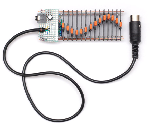
I left the chips exposed for now in case I need to reprogram them, but maybe I'll enclose it properly later. Since the sliders were hard to see, being black on black, but probably too close together to fit ordinary caps to them (plus I don't have any) I used some orange heatshrink tubing to cover them. While it's still warm you can reshape it a bit, so I pinched the ends together to make it a sealed blob-shape. It was easier to use that fifteenth slider as a mould and then pull it off and shove it onto the correct slider.
The MIDI cable is attached with two bits of wire hooped over it and soldered down while pulled tight. The heat from doing this melted the cable a little and it got a really firm hold on it. I have no worries about how secure it is.
I stuck the pullup resistor and a big reservoir cap in the midi jack itself. The whole thing is powered by the midi signal driving it, as before. The audio decoupling cap (electrolytic, I know, isn't the best for audio) was chosen mostly for its form factor, sitting nicely against the audio jack, and it's complete overkill at 220uF. Most of the smaller caps in my drawer were physically larger.
I made the cable long enough to sit the synth comfortably on top of whatever keyboard is driving it.
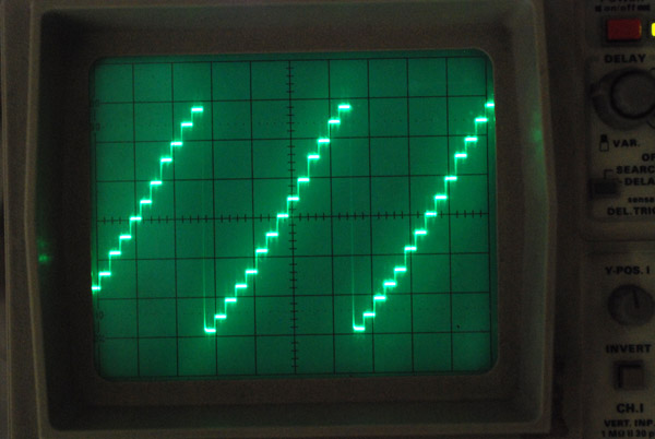
There we have it, a hand-drawn sawtooth...
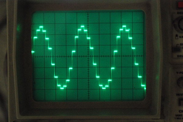
...and an approximate sinewave.
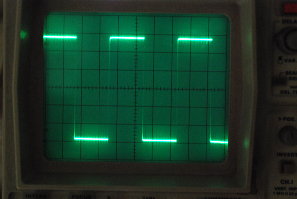
Of course square waves sound perfect, so full functionality is retained. In fact, I'd say the arpeggiated square wave almost sounds better, due to the step-down in frequency smoothing the transitions.
Overall it sounds great, even if the range of sounds isn't particularly exciting with such low resolution and no filters or anything. But maybe we've been spoiled by the software Reverse Oscilloscope! Actually I've spent the last few hours playing with this and combined with the arpeggiator and variable modulation it has a pretty impressive range of tones. I'd say it easily beats the Korg Monotron in the range of noises it can make.
To get closer to the software synth, I don't care about polyphony of course, but it'd be nice to have multiple oscillators for chorus and detune. We could have another multiplexer running at a different speed feeding both outputs into an op-amp. It'd be pretty easy to run one at 1.5x speed for a fifth, not sure how you'd do a 1% detune though.
We could output a gate voltage from the midi chip, and use this as the bias voltage on all of the pots. Then, by adding a capacitor/resistor to lowpass it, we'd have a simple envelope for each note. The counter would have to keep ticking while the note was stopped, but that's easy enough. Or we could use the differential output mode of a PWM channel as the two rails for the sliders, which would lets us digitally control the volume / envelope. Might have to add another ATTiny for that though (or, shock horror, upgrade to a chip with more pins!).
It would not be hard to add waveshapers to it too. A single ATtiny85 has analog input and sort-of analog output with the PWM so we could drop one in and have a lookup table. I would want to control the gain with a physical knob, but since it'd be 8-bit audio we would want to apply it digitally or it'd be horrible. So fill the 8kB of flash with lookup data for waveshaping at various gain values and it should do fine. This would mean we'd need to periodically sample another pin to know what gain is meant to be applied.
Hmm... you know what I'm tempted to do now, given how those sliders do look a lot like drawbars, and listening to the warbling modulation it currently has... build another setup in reverse-spectrum mode. A tiny hammond organ. This'd require a fourier transform of course, but nothing we can't handle. Might be tough on a chip without hardware multiplication though. Right, time to order more sliders!