
Ghetto soldering tweezers
27 Mar 2025Rambling Preamble
I have a tendency to be extremely frugal. Mostly because, until recently, that was the only option. When I soldered the WLCSP ATtiny20, I used a Maplin-branded soldering iron as it was the only thing I had. When I finally bought a TS100, which I think cost almost £60, I considered it an extravagant, but worthwhile, upgrade.Even with the newer TS101, people frequently criticise me for using the wrong type of soldering iron: "Use a smaller tip!" Partly this is due to the macro closeups making it hard to judge the size of things, but with the success of the pendants, I thought that perhaps I should invest some money into proper equipment. I had a look for microtip / nanotip soldering irons, meant for soldering really small stuff. Initially I saw a price tag of £50 – great! No, wait, that's just the replacement tip. The soldering stations themselves cost almost £2000.
I'm not quite sure what benefits can be reaped from a soldering station that costs as much as a small car, but surely it's not twenty times better than the iron I'm using.
I do have some qualms with my current setup, for instance, I'm paranoid that the soldering iron might suddenly break and leave me stranded. It's not an unreasonable worry: my TS100 eventually gave up the ghost when it smashed on the floor. To be fair, it had suffered quite a lot of abuse. A new TS101 costs so little these days that I quelled the anxiety by simply buying a backup. Now I always have two working soldering irons in stock.
There's a range of TS100 or Pinecil tips available, I don't know if the range has expanded lately or I just missed it originally. There are a couple of very small tips, such as the "TS-ILS" and the "TS-JL02" which only cost a few quid each. I don't know how they compare to the fancy nanotip soldering station, but honestly beyond a certain size it's simpler, as I've demonstrated in the past, to construct a single-use microtip out of a bent bit of wire wrapped around the end.
I did at one point, in my mission to invest in "better equipment", purchase a pair of soldering tweezers. These are not tweezers to accompany soldering, these are tweezers to perform the soldering, with two heated irons mounted to a hinged join. They seem particularly appealing for desoldering surface mount parts.
Most distressingly, the soldering tweezers I bought were faulty on arrival, but as I didn't need to do any desoldering at the time, it was a few months before I tried them out and discovered the flaw. Only one of the heating elements worked. Unbelievable. Outside of the return window too.
Luckily, since I had two working TS101 irons, I could just dual wield them and desolder with almost, but not quite, the dexterity of soldering tweezers.
Stands Plan
Perhaps the main complaint I have about the TS100 series is that it doesn't come with a good stand. There are a few crappy holders available, which are useless, and the standard size soldering iron holders (the coiled spring, and so on) are all too large to hold the narrow-bodied iron. The TS101 has a moulded thingy to help it sit flat on the desk, which is fine except for two problems: one, that it's easy to nudge it while hot into melting some nearby plastic item; and two, that it invariably ends up on the floor when the cable gets yanked. I've tried draping the cable through better routes, but to have enough slack to use the iron freely means having at least a loop of cable dangling free to snag.What I needed was a decent stand.
You may have noticed that I'm not a huge fan of 3D printing, at least not where the laser cutter could do a much better and faster job. I recently had some problems with my laser cutter and for a while had to rely on the miserably slow performance of additive extruded plastic.
It's particularly upsetting when we need to produce a planar shape that could be laser-cut in seconds. For instance, I was tidying my desk not long ago, and wanted to make a couple of rails to organise my pliers and snips. These 3D printed brackets slot into the standard linbin-style wall racks and hold some steel rollers that came out of a photocopier.
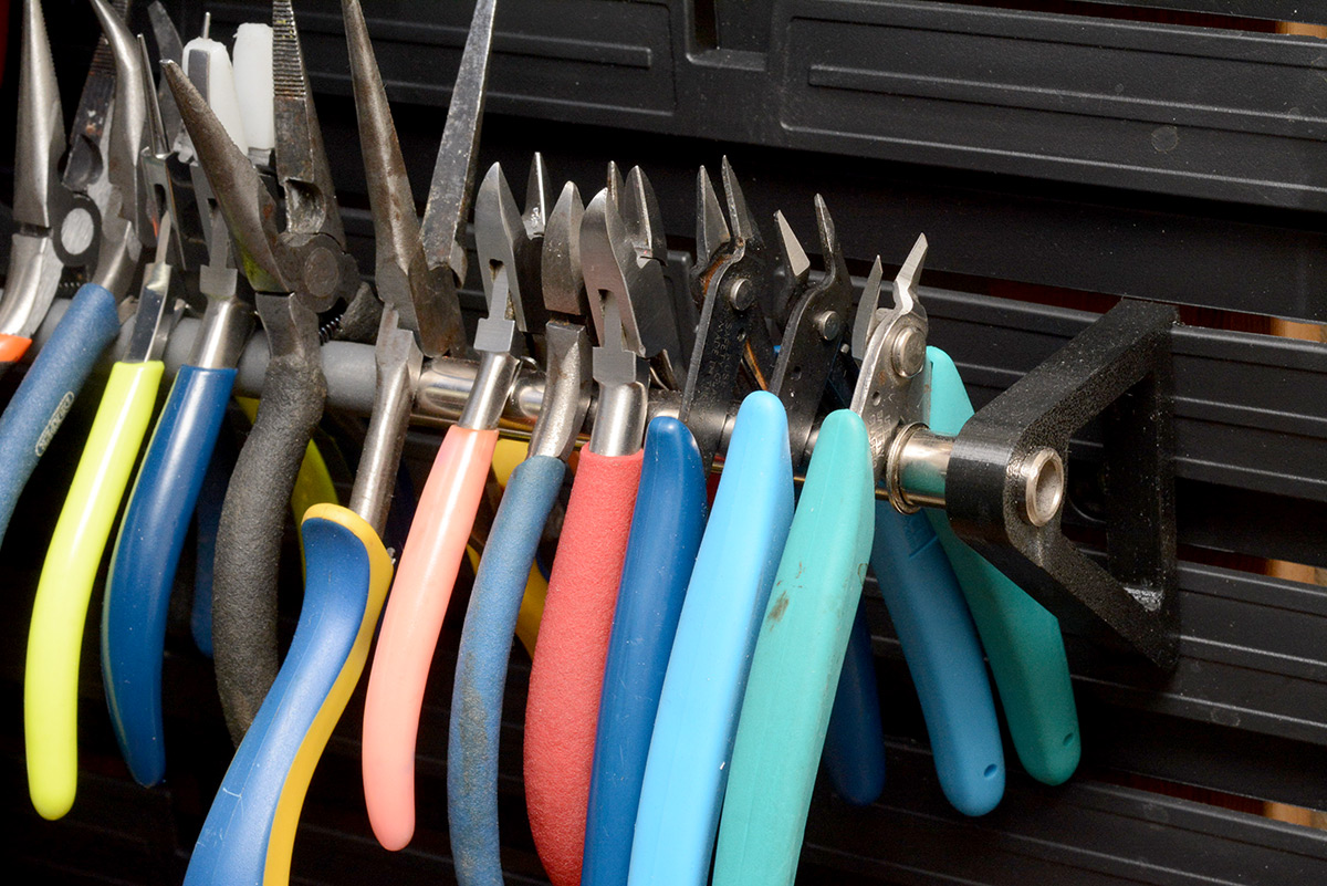
They work great, but in the three hours it took me to print a bunch of them I did nothing but grit my teeth and pine for the laser cutter.
In contrast, a stand that conforms to the contours of the TS101 is something much better suited to 3d printing. A few people have designed them, usually using a washer or ball bearing as a collar to hold the hot end, but none were quite what I had in mind. A surprising number of designs out there are meant to store it only while it's cold, which is kind of confusing.
What I want is something that stays put. Something where, if the cable gets yanked, it fights back. Ideally the iron should hold fast and the USB cable should pull out. We could easily do this by holding it by the base, and clamping the stand to the edge of the desk.
I frequently clamp cables to the edge of the desk with little quick-grip clamps, it's a very good way of protecting delicate circuits from the floor.
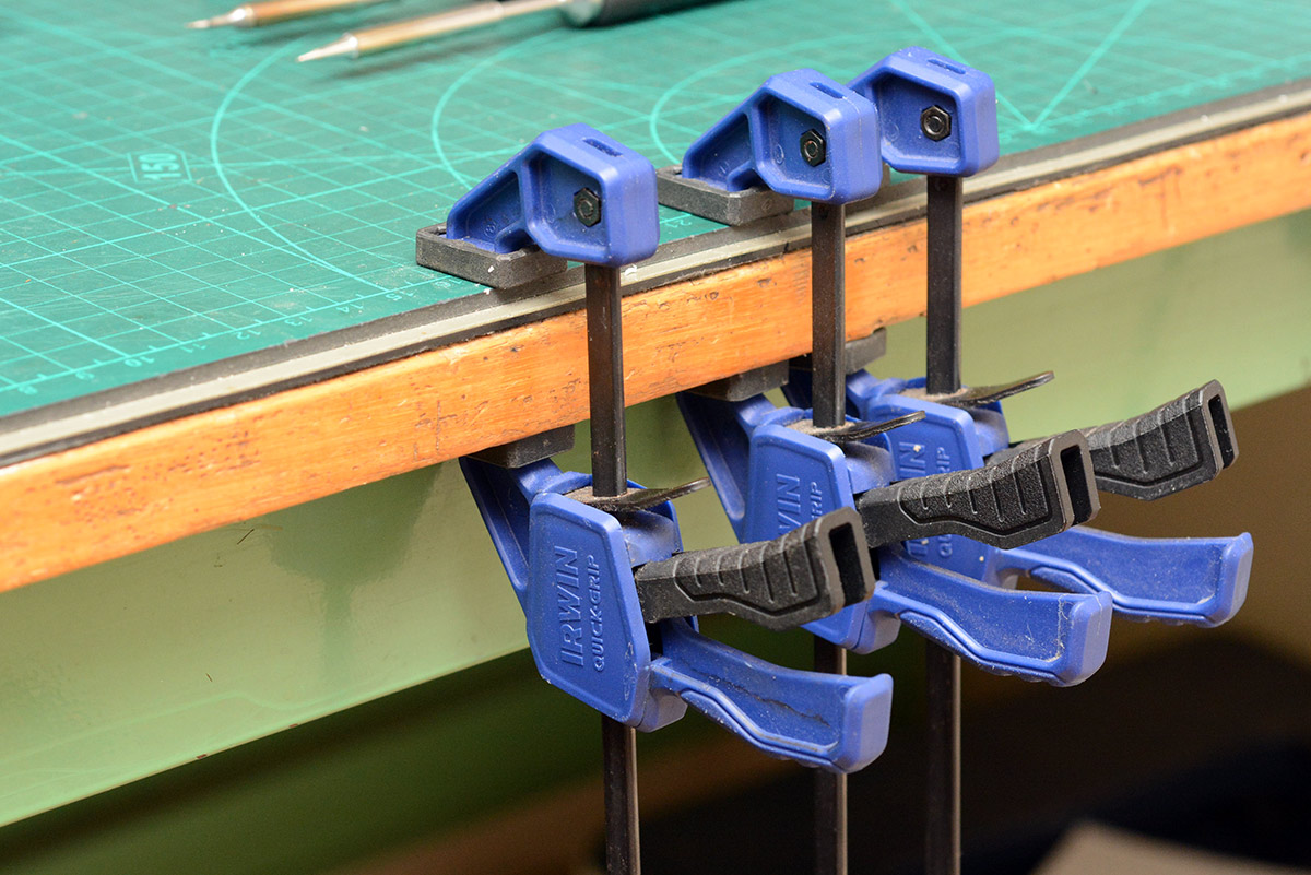
I considered 3D printing something that attaches to one of these grips, then we don't have to make the clamp mechanism. But designing a secure attachment to that moulded shape is non-trivial and probably more effort than printing a simple clamp.
It later occurred to me that we could replace the entire "head" of the clamp, bolting our 3D printed replacement to it. If done well, it would still function as a usable clamp. I may revisit that.
To FreeCAD
I really, really want FreeCAD to succeed. I want it to hit the same critical mass as Blender, but that is a long, long way away. The glitches and lack of features are such that few people use it, and without users it's not going to get better. I remember when KiCAD was a glitchy mess with a confusing workflow, and it suddenly got an influx of users (myself included) when Eagle got bought and crippled by Autodesk. In the following years KiCAD leapt forward and is now pretty robust (though still not in the same league as Blender).As an intermittently paying user of Fusion, I absolutely hate it, mostly because it is cloud-based and a subscription model. But when it comes to getting work done in a commercial setting, it's what I turn to because it's leaps and bounds ahead of the open source options.
One of the problems with trying out the free alternatives is that it's hard to know if we're hitting the limitations of the software, or just struggling with the learning curve of the workflow. Making a bunch of simple parts is the best way to learn, so with the recent release of FreeCAD 1.0, I thought I'd try and force myself to use it whenever there's no deadline involved.
I don't think it's helpful to list all the specific problems I encountered, with any luck the list will be out of date soon. Despite the promised stability improvements, I still had a couple of segfaults and an error message that said "Please report!" while making this simple clamp.
Often when I look up how to do things, the answer is that I shouldn't be doing that. It's fair, in a way, but coming from Fusion it does feel quite frustrating. Certain features simply make life easier. For instance, mirroring a sketch in FreeCAD copies the lines in an unconstrained way. You have to manually add all of the constraints again if you want them to be linked. The quoted reason is that sketches shouldn't be mirrored, geometry should be mirrored, but in some cases that can make it much harder to build your design.
I am very much a newbie at FreeCAD so I'm probably doing lots of things wrong. A relatively simple task I wanted to do was check the range of motion on the pivoting part. I made an assembly from the two bodies and added a revolute joint. This lets us swivel the pivot back and forth and see where it interferes.
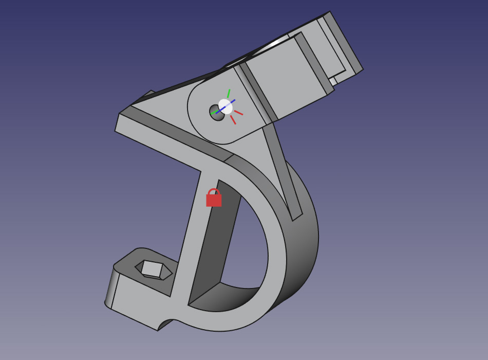
It didn't quite reach the vertical, so I went back to the sketch and very slightly adjusted one dimension – specifically, not enough to change the topology in any way – but FreeCAD got very confused, trashing the joint, the positions and the overall shape. The joint became un-deletable until I had saved, exited, and restarted the program. I'm not sure what I did wrong but after several patient attempts at this I gave up.
It seems that if you click and drag on a part in the Assembly workbench the position is captured immediately. There are dozens of minor annoyances I won't go into, a lot of it is my own ignorance of the program, some of it is missing features, and some of it is stuff that's just plain broken.
Possibly the most annoying problem I kept hitting is that the docked Tasks window often has a scrollbar. If you use the mouse wheel to scroll down, it will scroll a bit until it overlaps with an input field, and from then on it will alter the value in that field. I frequently scroll up and down in the pane and end up altering values I didn't want to touch.
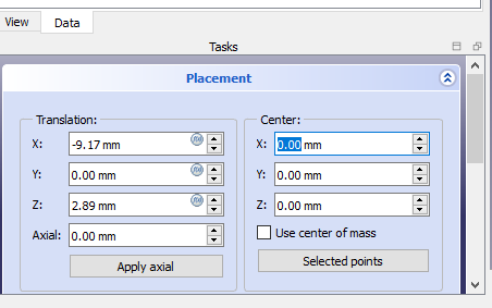
Such a basic UI problem is kind of embarrassing when Blender does it so well. In Blender you can middle-click pan in any window pane in addition to the scrollbar, you can drag values but only if you click on them, the dragging warps when needed and you can hold a modifier key to change the speed. That's all in addition to being able to click the little arrows, or type in formulas, or keyframe any field, set drivers, and so on. Everything in Blender starts with familiar UI concepts, and is extended in ways that add features without adding surprises. As far as I'm concerned, Blender has set out exactly the right way to do window panes and everybody else should copy it.
To the Printer
The clamp body was printed on its side, with support for the top section. The pivoting part was printed in the other plane then attached with an M4 bolt, just tight enough that the angle can still be adjusted.
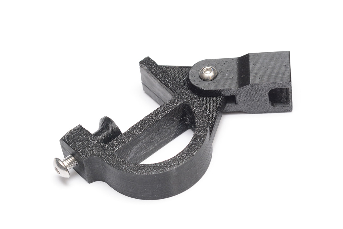
I also printed a little foot for the M5 clamping bolt. I considered printing a thumbwheel for it too, but you can buy thumbwheel bolts for pennies from China, so that's what I did. However, at the time of writing the thumbwheel bolts from China haven't yet arrived.
I glued a bit of bicycle inner-tube to one face to give it a nice grip on the desk.
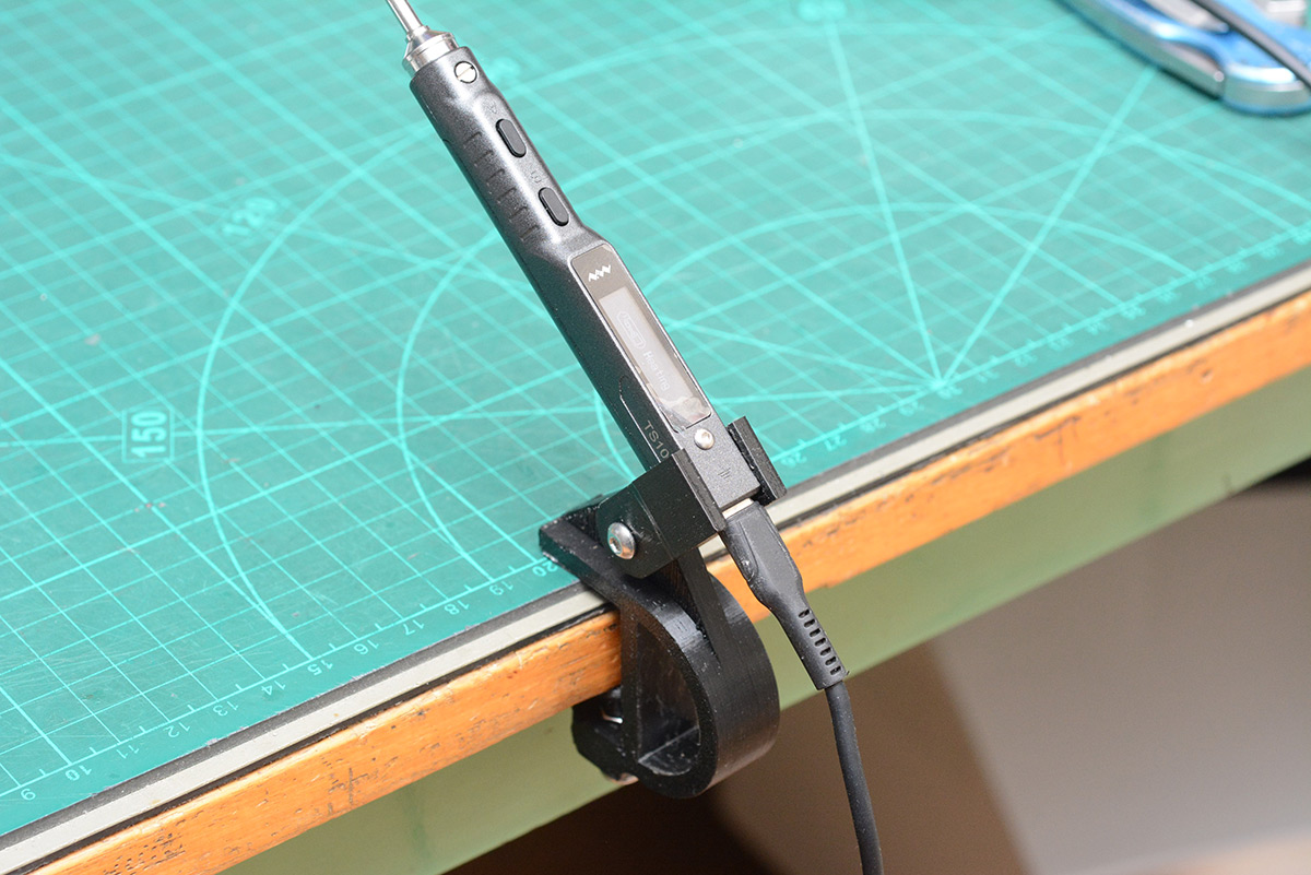
The iron slots in from the top, with the USB cable having just enough clearance. This holds it securely, and importantly if the cable is yanked it just unplugs the USB.
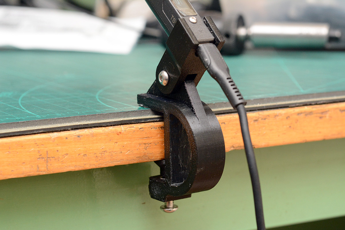
I possibly could have made the part that holds the iron bigger, to give it more grip, since in my tests of yanking the cable it sometimes bounced out of the holder. But in the week or so of actual usage I've given it, the holder is perfectly adequate, and the design as a whole solves the problem I had.
Aside: To extend the clamping section, in Fusion it would take a few seconds. In FreeCAD, the only way I can see to do it is to project the geometry onto a sketch on that face, then manually trace the whole outline including the curves, then pad that.
Tweezers idea
This week, some circuit boards I had assembled in China came back with an incorrect part fitted, which means I have to replace a hundred 0603 parts, and that had me thinking again about soldering tweezers.The TS101 is less than half the price of equivalent soldering tweezers. And, I already have two of them. One in each hand is not as effective as a tweezer arrangement, which leaves a spare hand to manipulate other things. But what if...?
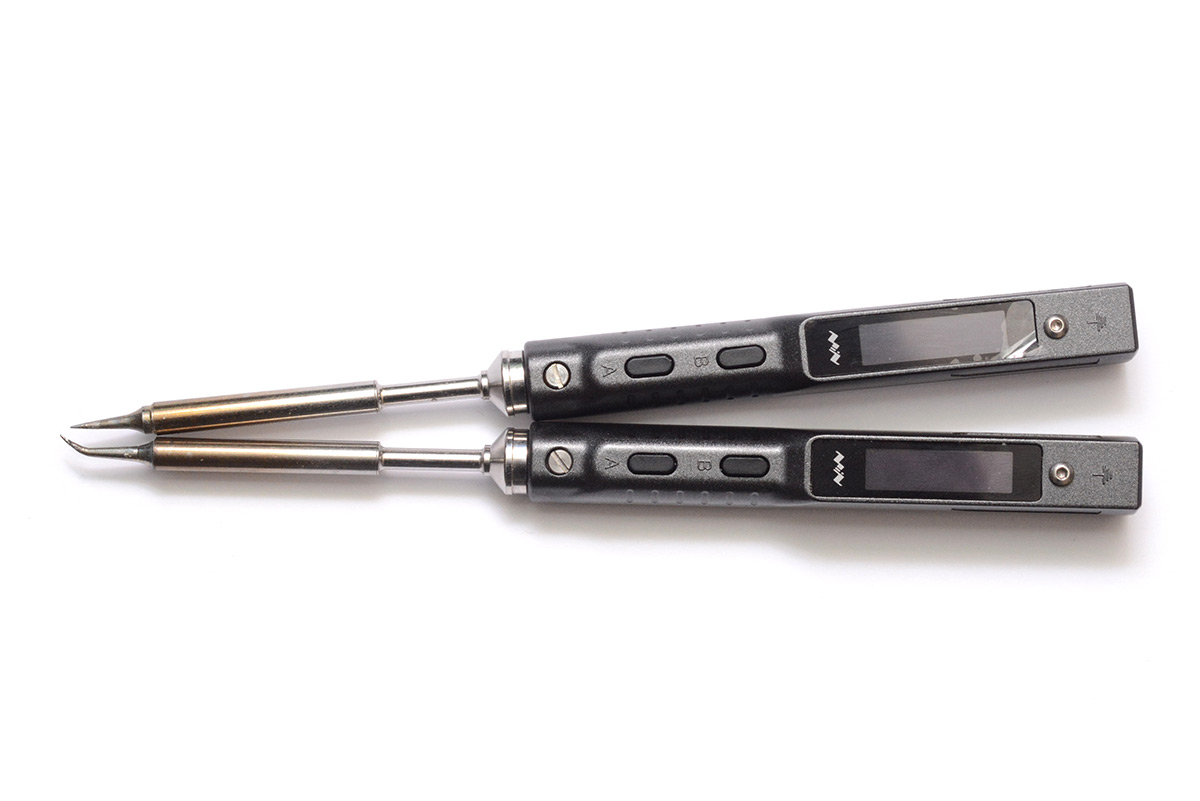
It's not impossible to chopsticks the two irons in one hand, but with the weight of the power cables it's tricky to wield. A 3D printed tweezer adapter could make it a breeze.
I tweaked the shape of my TS101 holder to have a little more grip, lengthened it, doubled it, and added a compliant tweezer mechanism.
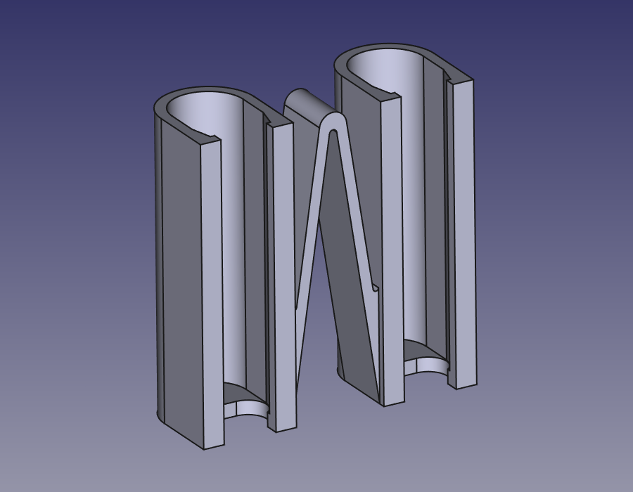
Yes, this time the geometry is mirrored, and I won't go into the troubles I had getting certain things to work.
I printed it out and to my amazement it works really well!
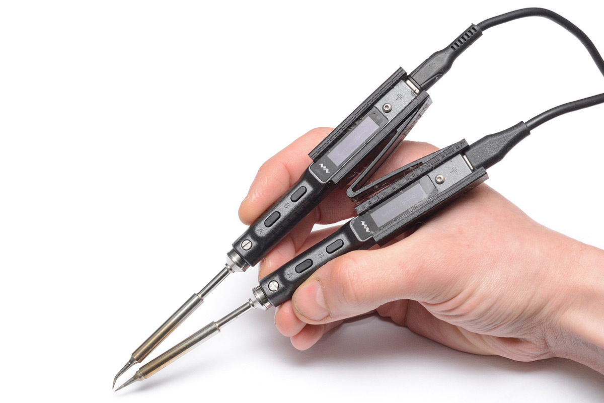
Ideally, the two irons would have identical tips fitted. I've ordered some more tips, but in the mean time I added a means to adjust the lengths. A hole at the bottom is threaded M2 and a bolt can be used to set the position.
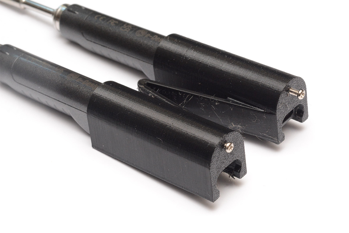
This is mainly a depth-stop, as the design grips the irons with plenty of friction.
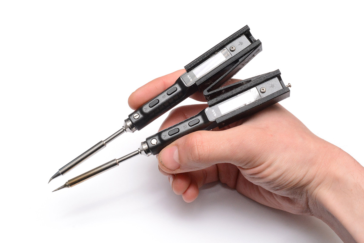
The hinge was a complete guess, I was worried it would be too stiff but if anything it could be stiffer. I certainly don't feel like they're in any danger of snapping, despite the plane it was printed in. This was in PETG as that's what I had loaded in the printer, but I expect PLA would be fine too.
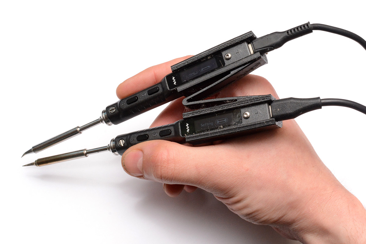
Perfectly cromulent soldering tweezers, I'd say.
Matching opposed tips will probably improve it somewhat, but even this is easily good enough to power through all the SMD parts I need to replace.
Download
Feel free to print your own ghetto soldering tweezers. Here's the STL file and the FreeCAD design.
Also available, the bits to make the desk clamp TS101 holder:
desk-clamp-body.stl,
desk-clamp-pivot.stl,
desk-clamp-foot.stl.