
FLIP Fluid on Flip Dots
24 Sep 2026Progress: Complete
Here's the story of how I put a FLIP fluid simulation on a flipdot electromechanical display. FLIP stands for Fluid Implicit Particle, and yes, the primary motivation behind doing this was the wordplay.
It was built as an installation for EMF2026. This page will mostly focus on the technical details, but for the overview and demo of it working, watch the following youtube video.
- Intro
- Path to Some Panels
- Connect the Dots
- To KiCad
- Second Circuit
- Mounting Dreams
- Panel Preparations
- Prototype Polish
- Framework
- Decoder Boards
- Power Supply
- Joystick
- Motherboard and Power Bus
- Logo
- The Event
- Conclusion
Flippin' fluid simulations
For the last few years I've been building all kinds of fluid simulations, though the only things I've made videos about are the volumetric display and the fluid pendant.While most of them are still secret (I'll publish them eventually) they all have a common deficit, that is, the LED liquid is utterly silent. I'd been wondering whether I could simulate some swishing noises when it occurred to me that an electromechanical display, such as flipdots, would make the noise for us. Realising that it would also make a great pun sealed the deal.

But flipdot displays are crazy expensive. From what I can gather, there's only one manufacturer still in existence, and they have exclusive deals with a small number of artistic studios. Breakfast Studio is probably the most well known, and they aren't interested in talking to anyone with a budget of less than $50,000.
By pure coincidence, at one point I did a bit of contract work for a company that happened to own a big flipdot display, and I tried to convince them to let me play with it. I genuinely offered to forfeit my salary in exchange for putting a fluid sim on their display, and to my astonishment they turned me down. I guess that sealed it: I would have to do it the hard way.
Path to some panels
Asking around, especially at hackercamps, led to a bunch of interesting conversations. A lot of people are interested in flipdots. There was even talk of forming a collective and ordering newly made flipdot panels from China. Surely if anyone can produce these displays for cheap, it's someone in China. But the manufacturing process is remarkably complicated. Even the disks themselves are a sandwich of maybe six different materials – here I've dismantled one of the disks I eventually used:
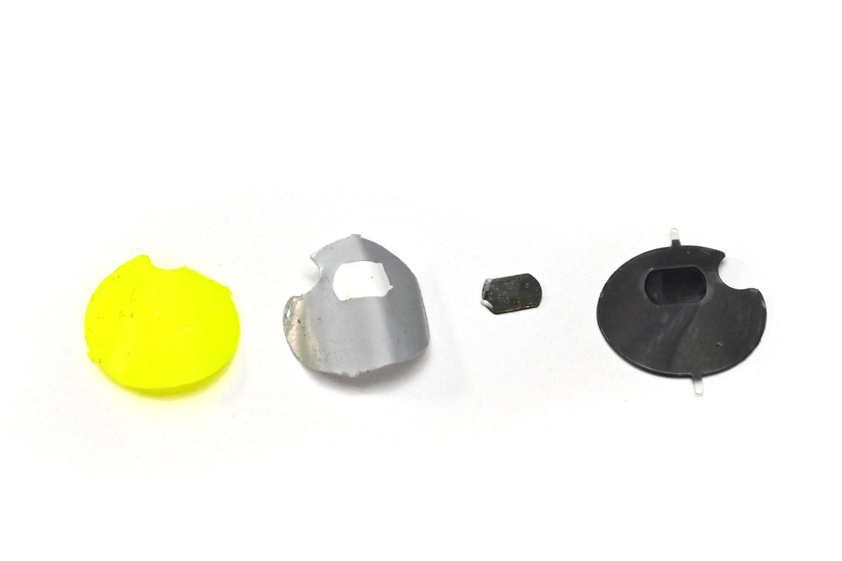
It's not as simple as just a coil moves a magnetic part. The dots are non-volatile, so they hold their position when the power is removed. There are two permanent magnets (one inside the dot, above, and one in the base) and two cores which can be polarised to set the state of the dot.
Some people I spoke to had some of the new flipdot displays from AlfaZeta, but most people had old ones from eBay almost exclusively manufactured by Hanover, who still exist but no longer make these types of displays.
Aside: a number of my projects have been copied by people in China. If, after publishing this, some company in China starts churning out cheap flipdot displays I think we'll call that a win.
Eventually I got in contact with Sam, aka Look Mum No Computer. His museum of obsolete technology has put him in the enviable position of occasionally receiving cool donations of weird old tech, and one of these donations was an enormous pile of old flipdot displays. It's unclear if they are reclaimed from old buses, or were new-old-stock. A lot of them are in pretty poor condition, but that may just be from how they were stored. Sam's plan was to turn them all into one huge display, but doing that would be a monumental amount of work, for reasons that will become clear in a moment. He was very happy to let me have a few panels to play with, with the promise of more if I could come up with a good way of driving them.
Here's one of the panels:
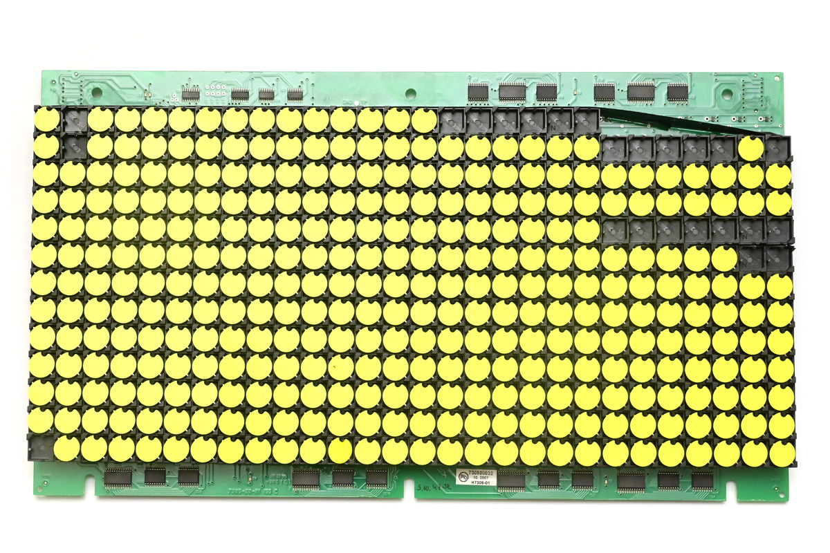
I kept this one for spare parts as it had some impact damage near the edge. At the top right I've managed to unsolder one group of dots.
The date code is 2007, which is younger than I expected.
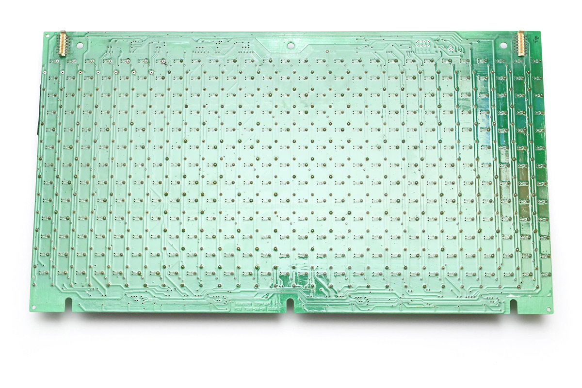
The rear of the panel had a protective sheet, which I've removed here.
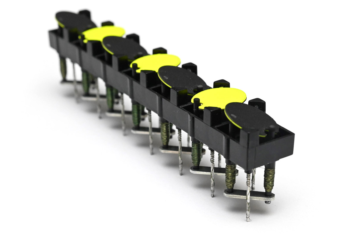
Note the resolution is 13 by 28. The dots on this panel were manufactured in groups of seven, which is where the 28 comes from. The 13 is probably a result of the designer's affinity for prime numbers.
Connect the dots
The number one problem with these panels is that the circuit board protrudes over the edges, which means we can't tile them seamlessly in that direction.The number two problem is that the existing drive circuitry is quite slow, taking about one second to update the display. The whole panel is wired up as one big matrix, which puts a limit on how fast we can update it.
Sam was able to get a bunch of the panels working with their original drive circuits, first building an etch a sketch and then a bigger display using a few of the panels. He mentioned that at least one other person had got them working with the original circuitry as well. But building one very wide display isn't enough, we want to tile them vertically too!
The person who got furthest is Mike from mikeselectricstuff, and his flipdot video was extremely informative, acting as my primary reference on how the dots work. The most interesting point is that while it takes around 60 milliseconds for a dot to flip over, it only needs a very short pulse to polarise the cores, maybe a millisecond at most.
Longer and higher voltage pulses can get the dot to flip slightly faster, but not significantly. One thought is that by using higher voltages, we can use shorter pulses, which would let us scan through the matrix faster. Taken straight from Mike's video, the matrix layout is something like this:
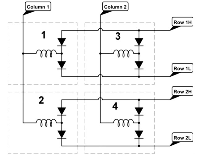
To set the first dot, you'd set the first column either high or low, and then pulse the relevant row line. As I understand it, the original driver circuit would hold the column line in one state, pulse through each dot that needs to be set one way, then change the polarity of the column line and pulse all the remaining dots in the column, and then advance to the next column.
It may be possible to build a faster matrix by pulsing all of the dots in the column in just two goes. Hold the column line high, simultaneously pulse all the relevant rows, then hold the column low and pulse the others. If the pulses are one millisecond, we could potentially update all 28 columns in as little as 56 milliseconds, which is about as long as it takes for a dot to flip anyway.
There are two problems with this approach. One is that the power requirements are substantial. Each coil has a resistance of about 18 ohms, which would be 666mA at 12V. For faster pulses we might be looking at 15, 20 or 24V, with over an amp per coil. For these panels with just 13 rows, having a driver circuit which can push and pull 13 amps for every column is going to be tricky. The bigger panels would need even beefier parts.
We might be able to split it into multiple smaller matrices, but the next issue is that any matrix will have visible artefacts. Even though it takes tens of milliseconds for a dot to flip over, if different dots start flipping even slightly out of sync, there is a visual glitch as they progressively change. Even with small matrices of say 8x8, or even 4x4, when you flip the whole display, there would briefly be a kind of checkerboard as each matrix wipes over. For what I want to do, that's not acceptable.
Logically the next avenue to explore is desoldering all of the dots, and mounting them onto new circuit boards.
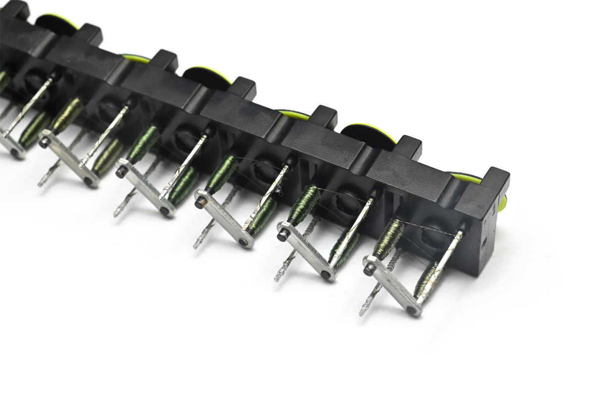
We had some discussions about fast ways to do this but ultimately concluded that it's just not worth the time. The dots are so delicate, with tiny magnet wires and soft plastic that can melt, that it has to be done very carefully. Even with the very best desoldering equipment it would take forever. It's possible that pre-sawing the PCB into pieces would help; it's possible that a specific jig to melt a whole group of 14 pins at once would help; it's possible that we could try to abuse a wave soldering setup to speed it up... but remember, what we're trying to do here is build a fast flipdot display that's cheaper than the commercial offerings. After desoldering we've got the added labour of soldering them again to the new board. Unless our time has no value at all, this is going to end up very expensive.
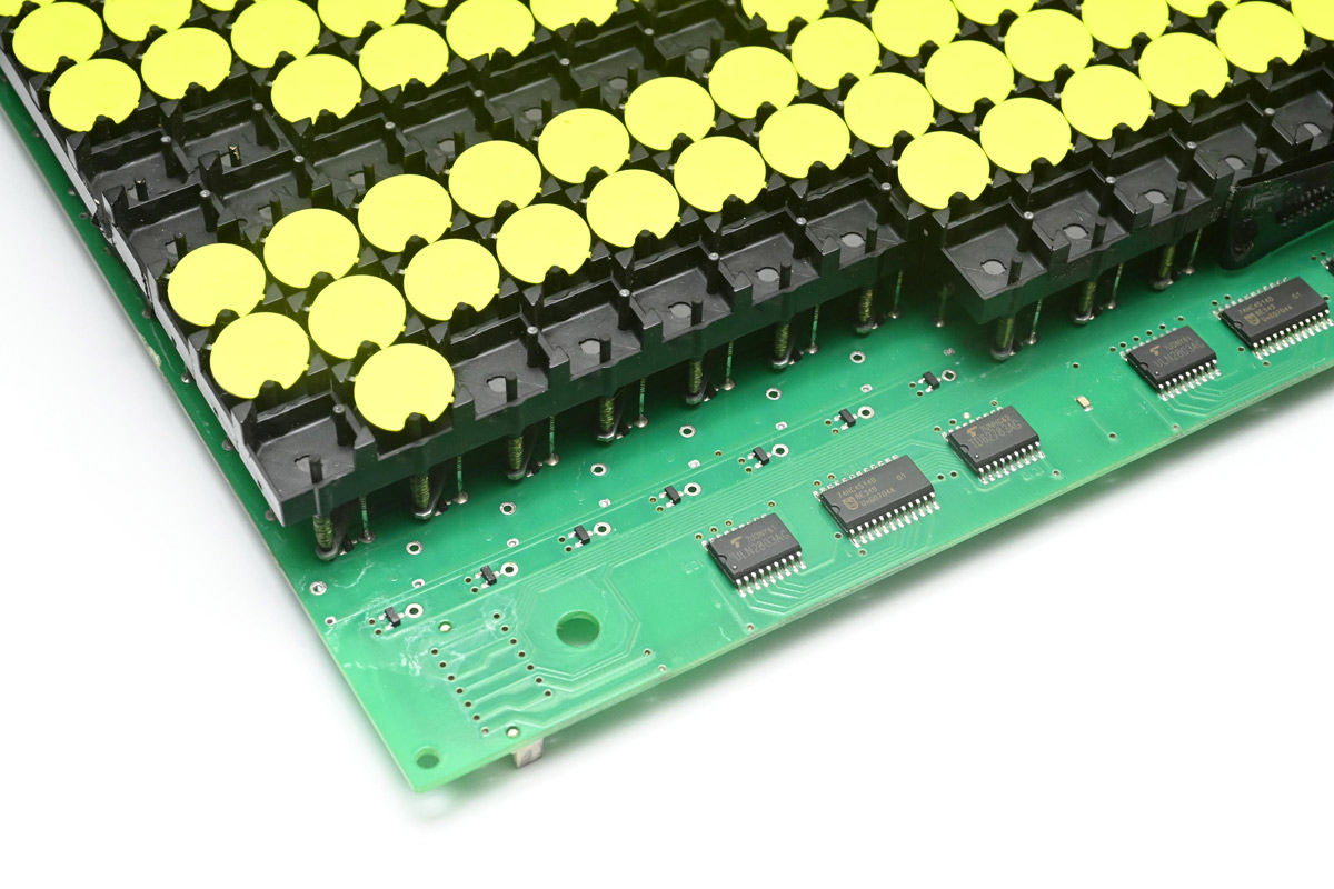
Mike's idea was to build a new circuit board that could solder directly onto the back of the existing boards. He found some very cheap H-bridge chips designed for driving small electric motors, which can run from 12V, don't need level shifting, and have built-in protection diodes. The parts have names like MX6208, BE6208, and LK6208, and one of them can drive a dot directly.
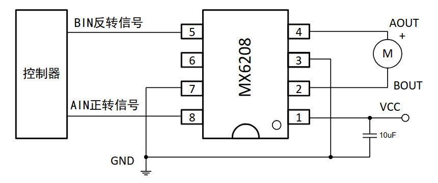
As you may expect if you've used motor driver chips before, the two inputs A and B are used to drive the outputs, with logic high and low corresponding to push and pull, but if A and B match then it either applies the brakes (setting both outputs to low) or allows it to freewheel (disabling both outputs). The datasheets conveniently give us the internal schematic and a truth table.
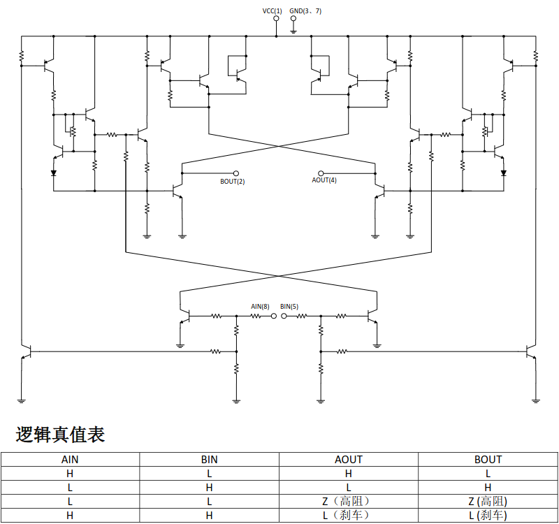
These parts are SOIC-8 and rated for 0.5A continuous, so they can comfortably handle our pulses. The only real disadvantage of using them is that we'd need to cut all the column tracks on the existing PCB before soldering them down. Otherwise, the pulses would interfere with each other. (The diodes on the row connections mean we don't need to cut those.)
Mike was kind enough to give me his prototype boards as a starting point, and I spent a while studying them and thinking about our options.
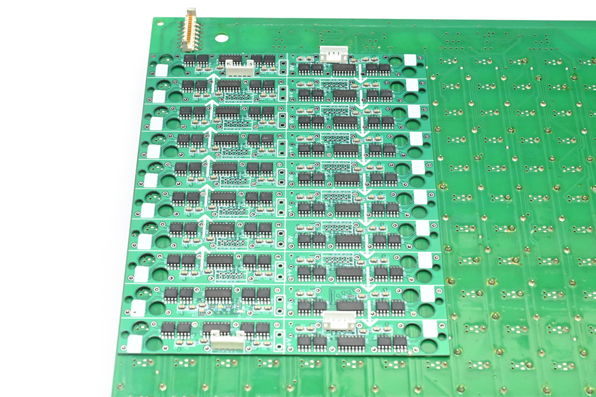
Typical of his designs it's filled with clever little details, like doubling up of the connector footprint so any of them can act as an input or output. Each shift register controls four dots, with the two inputs of each H-bridge directly controlled by the 8-bit shift registers. The latch and OE signals are tied together for simplicity.
The plan for these was to mount the whole panel in a small CNC mill, and use it to cut all the traces. Given that the edges need to be cut off too, this wouldn't be too inconvenient, if not for the fact I don't have a small CNC mill. Before cutting all the traces manually I tried to explore some more options.
Another technique for driving the dots involves using a series capacitor. There's a nice project here that uses the technique to build a new filpdot display. The advantage is that you don't need a full H-bridge per dot, only a single half-bridge.
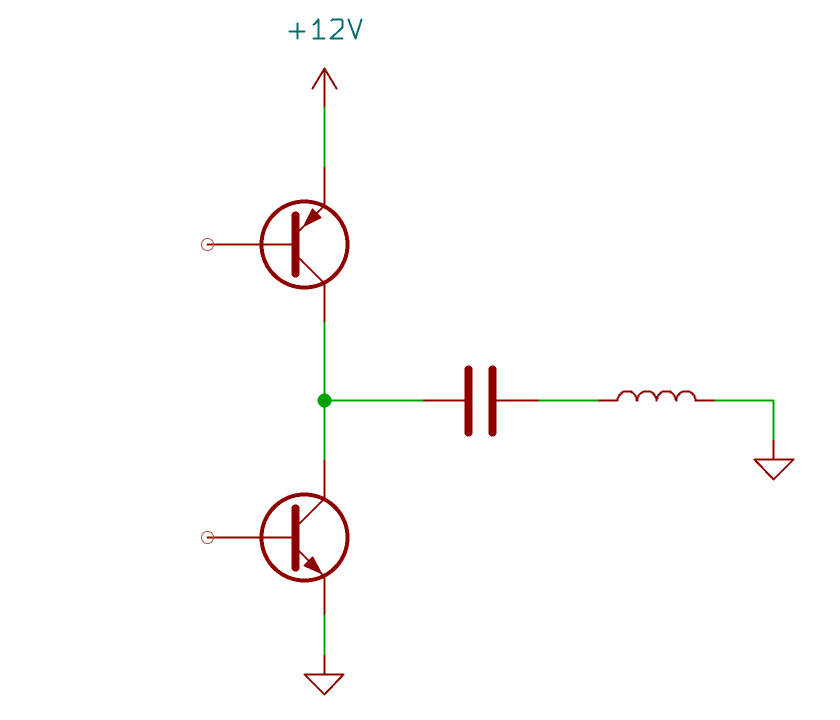
When the bridge goes high, a pulse is sent through the capacitor which flips the dot. The capacitor then stays (or is held) fully charged, until the bridge pulls it low again, creating an inverse pulse that flips it back.
Of course it's not actually as simple as that, to control the high side from logic level signals we'd need another transistor.
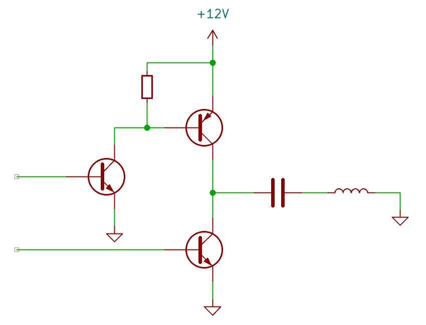
Naturally we'd use mosfets for the real thing. The linked project uses three mosfets and three pull resistors for every dot, in addition to the big capacitor. The biggest risk with building your own half bridge is the chance of turning both top and bottom switches on at the same time, which would cause it to explode. Another big downside is that having multiple discrete components takes up a lot of board space. The linked project uses a dedicated microcontroller for each group of seven, on a four layer board, and doesn't need to contend with soldering onto the back of an existing board.
In contrast the H-bridge chips are a self-contained solution, and combined with the very cheap 595 shift registers, Mike's board is much cheaper and simpler than the capacitor technique above.
But one thing about it really appealed to me: if one pin of each dot is grounded, we won't need to cut any traces. All of the column lines can be connected to ground. This also means we won't need to do as much soldering.
I did some test board layouts and found that we really don't have much space to work with. Certain areas of the PCB need to be empty to avoid shorting with pads on the original board, and we also need to leave space for mounting holes. Even if I wanted to do it with discrete components I'm not sure I could fit it. Thus began my search for a cheap, small half-bridge.
The first thing I looked at were gate drivers, these are dedicated devices for overcoming the capacitance of big mosfet gates. They usually have level shifting for us, and work like an isolated half-bridge that can momentarily deliver a huge pulse of current. Unfortunately, even the very cheapest ones are about twenty times the cost of those H-bridge chips. That'll compound when we scale up to thousands of dots.
Some of those gate drivers are available in SOT-23 packages, which would help a lot when it comes to board layout. There are also H-bridge chips available in SOT-23, but unlike the SOIC-8 parts they don't seem to have a standardised footprint. I compared dozens of them and found that nothing was perfect, nothing gave me confidence. I also looked at various "relay drivers" which had their own pros and cons.
Some shift registers have built-in output FETs that let them low-side switch a load directly. What I'd love would be a shift register with high-current push-pull outputs at a suitable voltage, but as far as I can tell nothing like that exists. There are high voltage shift registers if we go back in time to early CMOS technology like the 4000 series. A CD4094 shift register could work at 12V, but, the output capability is negligible, we'd be lucky to pull 10mA from it.
More options: there are buffer chips that could work in the ranges we expect. I found a few that would work electrically, but again, the price made them impractical, and most of them have footprints that'd be difficult to work with.
The idea of using one H-bridge to control a pair of dots was appealing but unfortunately not possible, because of their brake and freewheel conditions. However, given that the parts are so cheap, and we were planning on using one per dot originally anyway, would it be crazy to use them in a single ended fashion, ignoring one of the outputs?

It's not as easy as it sounds. Studying that truth table, if we send our signal to AIN, and hold BIN low, then AOUT would go high-impedance when AIN is LOW. If we hold BIN high, then AOUT would only ever be low. But if we send our signal to BIN, and keep AIN high, then the output will toggle high and low correctly (even if the part thinks this is a brake condition).
To see if this was even close to viable I built a test setup on some protoboard.
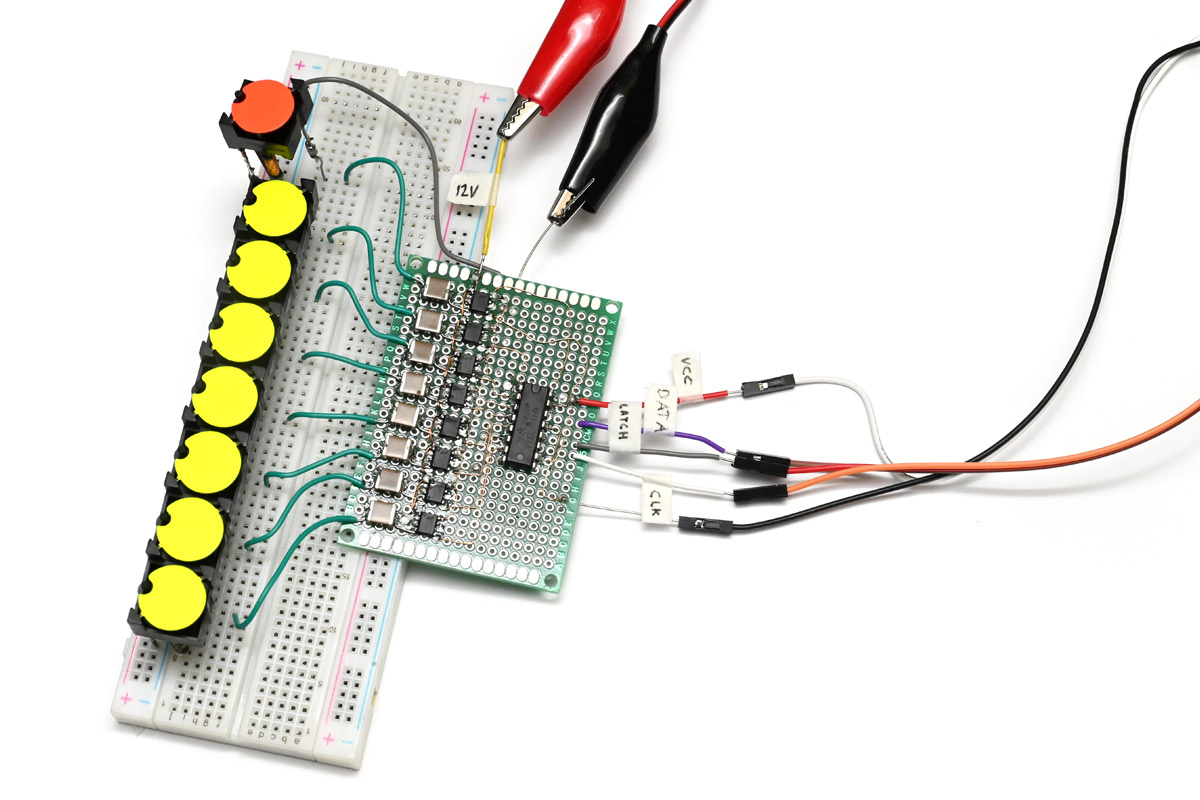
We have a 595 shift register, the H-bridge chips wired in single ended fashion wth AIN tied high. The capacitors are multilayer ceramic 100uF which were all I had to hand in the right ballpark. A nice bonus of wiring it up this way is that we can now drive eight dots from one shift register, so that's half the number of shift registers and half the data that needs to be clocked out.
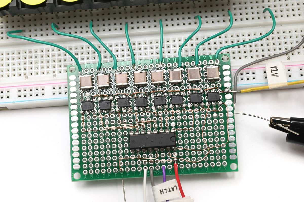
One of the lesser concerns with the capacitor method is that of self-discharge. I assumed this wouldn't be a problem because we can simply leave the outputs powered. No current should flow through the capacitor except enough to keep it at full charge. Unfortunately these chips are not built from FETs, but BJTs, so I soon realised that that was a mistake. When an output is enabled, even if unconnected, the chip consumes about 24mA simply because of the base currents through the transistors. Multiply that by a few thousand dots and we have a quiescent current that could kill the project.
Evidently we still need to pulse the signal then. If capacitor discharge is an issue, we can always periodically re-pulse it. Again looking at the truth table, we can use the AIN signal as an enable pin. I decided to tie this to the latch signal for the shift register. A minor benefit of the BJT inputs is that we don't need pulldown resistors: when the shift register's output is disabled, the H bridge inputs are effectively low.
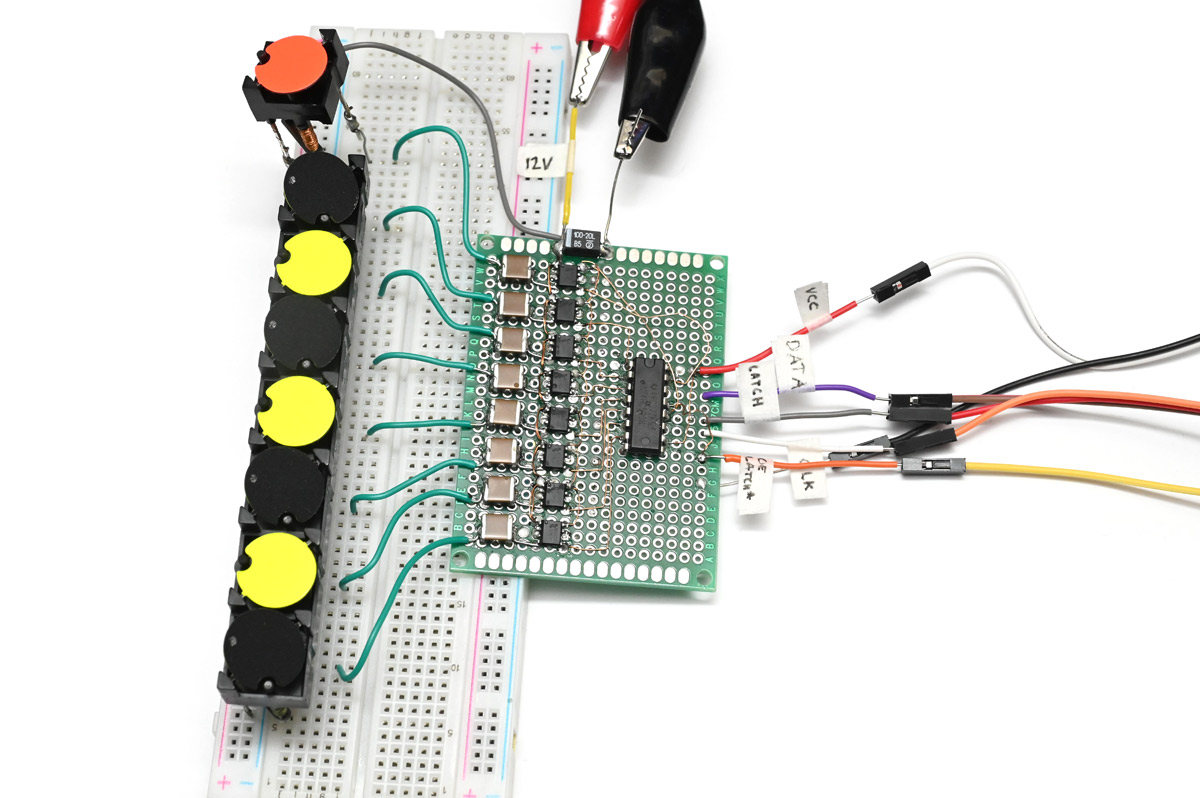
With this I felt like we were finally getting somewhere.
A neat thing about the series capacitor is that it comes with some inherent safety. If a glitch occurred with the direct drive method, it could hang with full current flowing through the coils, eventually overheating, maybe combusting. This circuit comes with far fewer ways in which it could conflagrate.
The choice of capacitor is important, those big ceramic ones weren't going to fit on our PCB. I adapted the prototype so I could stick various different capacitors in and see how they compare. An interesting thing about the 100uF ones is that only after the fact did I notice they were rated for 6.3V, and I'd been pulsing 12V through them. Using some 10uF, 16V rated ones gave a noticeably worse performance. I can't say I really understand the physics of ceramic capacitors, I know that the capacitance is a function of the bias voltage so already it's a bit of a mind screw. If we pulse a capacitor above its voltage rating does it reduce its lifetime? Probably. Cost is a factor here, with standard sized capacitors being significantly cheaper than speciality ones, and it's really gonna add up later on. I concluded that two 10uF capacitors in parallel would probably be enough, and then we can use standard 0805 packages for them.
Another thought: does the series resistance of a ceramic capacitor depend on its physical dimensions? A 10uF ceramic is available in various footprints at different costs, so there must be some difference in the technology used to shrink them. Instead of idly wondering, it was time to throw our first PCB together.
To KiCad
These flipdot panels have a pin pitch of 15.24mm, or six tenths of an inch. The board supporting them has test pads or an unpopulated footprint in the corner next to each one, so we'll stick a keepout around that. I created a flipdot symbol and footprint which we can lock into position on the board.But KiCad is really not very good at this sort of design, where we have lots of repetition. Unlike some other EDA software, there isn't a clear idea about forwards and backwards annotation. The original process was to create a schematic, export a netlist, and then import that netlist to the PCB editor. Newer versions have streamlined it to add an "update PCB from schematic" button, and in the latest versions there is even some attempt to add UUIDs to symbol-component pairs, but so far it's still a little janky.
The fundamental problem as I see it is that the auto annotation is useless. If you copy and paste some schematic symbols, you have a choice to leave them unannotated (so resistors have labels like R? instead of R3, etc) or to reannotate them based on their position (so resistors would be annotated based on the first free identifiers, in a left-to-right, top-to-bottom fashion). If you copy and paste parts on the PCB, you get the same options, but those are almost never helpful choices, because it's unlikely that the schematic and PCB will have the same physical layout. The effect is that if you copy and paste anything but the most trivial circuits, the schematic and PCB get annotations that don't match.
I did file an issue about this but I think I failed to convey exactly what I wanted and it got buried among a thousand other issues. The way it should behave – by default, if you ask me – is to re-annotate based on a predicable method that is independent of geographic layout. The most simple option would be to re-annotate in the same order as the source parts. So if you had R1, R2 and R3, they would become R4, R5 and R6 regardless of which one is to the left or the right.
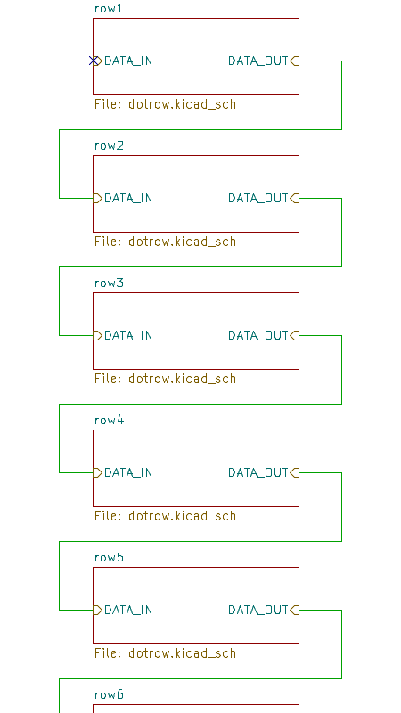
There is a plugin for duplicating layouts, but the approach they use is different to what I wanted to achieve here. What I wanted, and what KiCad can do once it was fought into submission, is a single schematic file that describes one row of dots, and a single hierarchical file that links copies of that row together. If we edit the row, all of them change and the netlist used by the PCB editor reflects that.
Frustratingly, the newly added UUID system makes it even harder to get this to work, but with enough wrangling and a little bit of python I got there in the end. The overview looks like this:
And the dotrow.kicad_pcb is of this sort of persuasion:
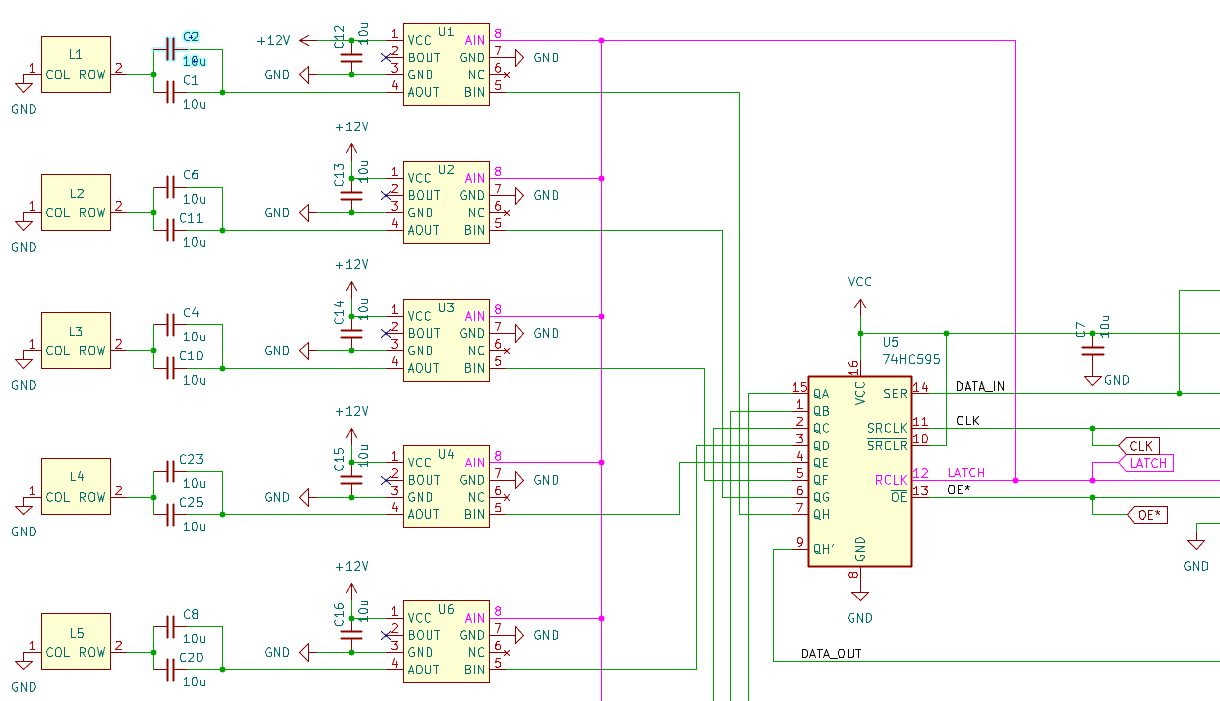
There I've highlighted the latch signal going to AIN of each driver. The two 10uF capacitors are in parallel before each dot. If we open the same schematic for the next row, the layout is identical but the annotations are all different.
I based the PCB layout loosely on what Mike did, adding the dual footprints for serial data and some mounting holes, which I carefully checked would not interfere with any tracks on the underlying PCB. I extended this to 13 rows, so it would cover the full height of a panel.
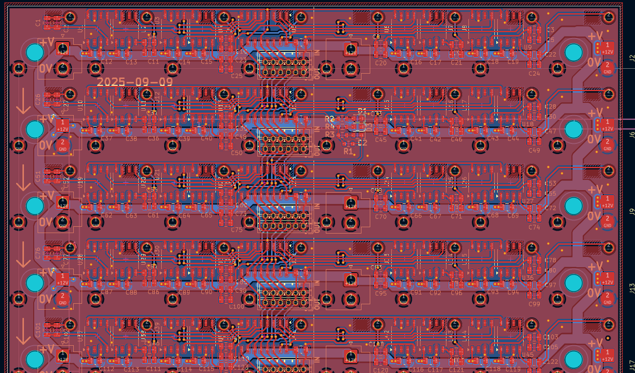
Horizontally, we cover eight dots, so we'll need three and a half of these to drive one full panel of 28 columns. That's a bit awkward but we can deal with it later, for now I just wanted to confirm the ideas. While I waited for the circuit boards to arrive I made this 3D printed fence for a dremel with a diamond wheel, so we can efficiently cut away the old driver circuitry.
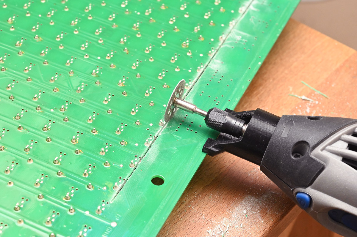
The cut distance is different for the top and bottom of the circuit, which is slightly awkward but when it comes to preparing all of the panels, we can do all of the tops first, readjust, and then do all the bottoms.
When the circuit boards arrived, we held our breath as we soldered the 117 pins necessary (13 x 8, plus 13 grounds).
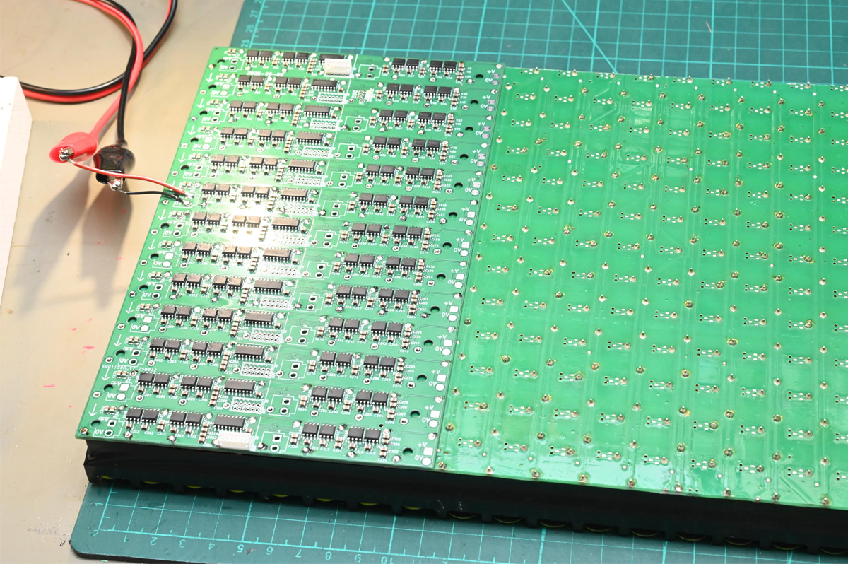
Initial results were mixed.
Flipping individual dots worked, but flipping all of them at once would fail. If each dot needs a pulse of around half an amp to flip, then flipping all of those would be about 50 amps, if only for a millisecond. As the power supply couldn't cope, the voltage drops, and the pulses become weaker. Instead of polarising the cores, they simply demagnetise the cores, and the dots go slack.
I noticed early on that the behaviour at lower voltages was significantly different with different series capacitors. Limiting our selection to 0805 ceramics, even doubled up, was probably a mistake, as they seem to suffer more from the undervoltage condition than a single big capacitor.
Another issue is that the inputs to the H-bridge chips draw significant current. The input is the base of a BJT, so unlike CMOS parts it will draw a few milliamps, and multiplied by a few hundred means the latch signal now needs more current than can be provided by a simple GPIO pin. I was driving this from a basic CH32V003 breakout board that was struggling to keep up. No worries, we can bodge in a mosfet to boost the current.
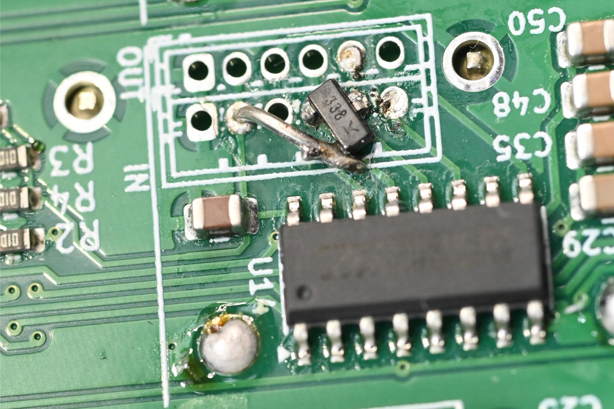
That's a P-channel mosfet (FDN338P) on one of the unused connector footprints, with its gate connected to the OE signal. This suits me fine, we were already toggling the OE and latch signals alternately. This also saves us one pin on the connector.
I went with JST ZH connectors (1.5mm pitch) partly because I already had a pile of ready-made cables. These cables turned out to be just slightly too short, and I had to manually extend them...
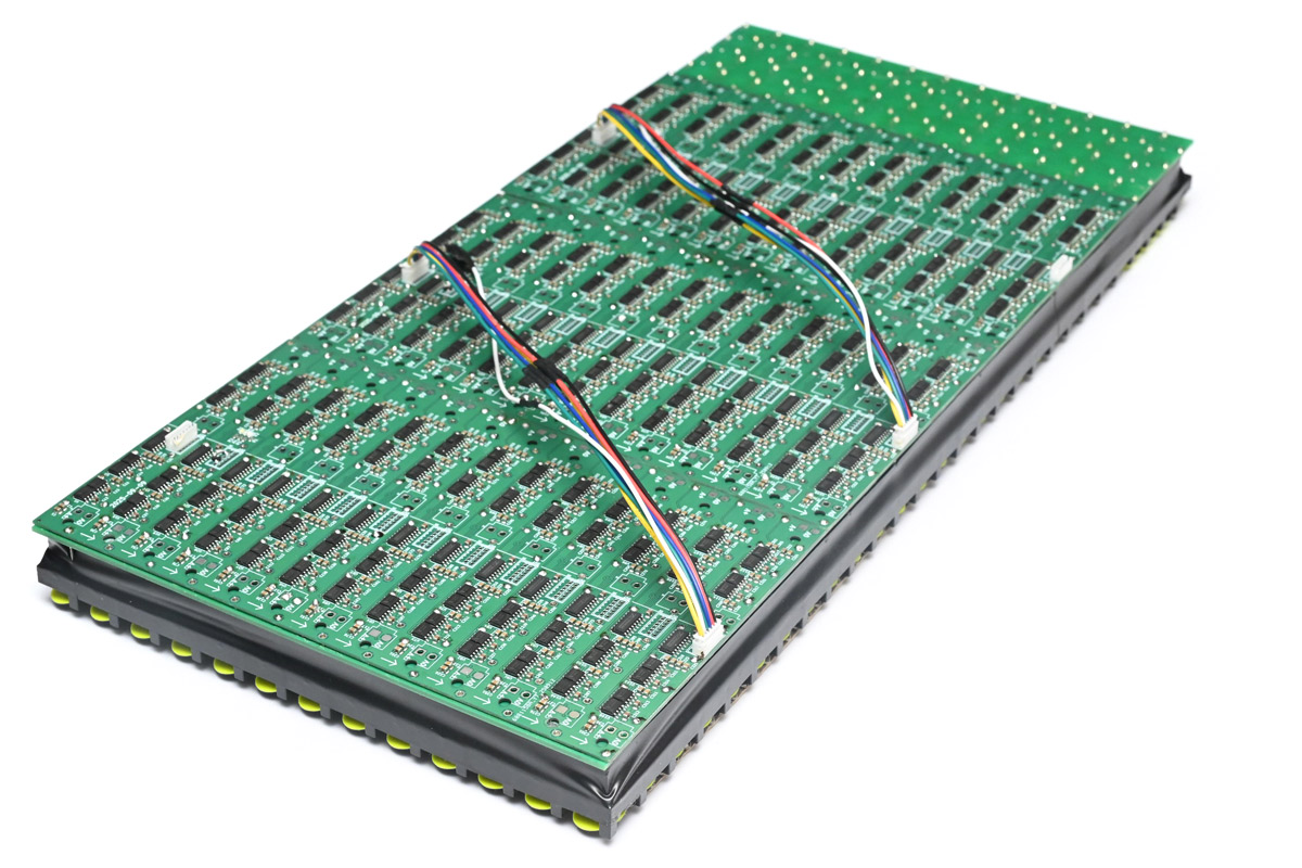
The white wire is the former latch signal, which I've disconnected as it made sense to stick a mosfet on each of the panels.
I noticed an asymmetry: it's easier to flip in one direction than the other. You might think it's to do with the capacitor arrangement, but counterintuitively flipping from high to low is faster. Simply due to the physics of transistors, the low-side switching can sink more current than the high side can source. Another way of thinking about it is if we'd driven the coils directly from the H-bridge, the flipping would be symmetrical, but only because both directions would be limited by how much current can be sourced on the high side.
With more of the dots active, the dependency on a decent power supply worsened. With two benchtop supplies in parallel I could just about get all of the dots to flip at once. We can up the voltage (the drivers are rated up to 15V) but I really want the final thing to work with a 3S LiPo battery (from 12.6V down to 9.0V).
While experimenting with different power supplies, inevitably I ended up touching a 12V signal to one of the data lines, and one column of shift registers disintegrated. Nothing is more discouraging than destroying your dev board, so I decided to take a break.
Second circuit
About six months later I came back to this and figured that power supply problems are best solved by flooding the thing with electrolytic capacitors. Some of the surface mount ones are actually cheaper than ceramics. What's more, the behaviour of electrolytics as a series capacitor for the dots seemed to be much nicer, so we might as well replace all of them with the biggest electrolytic caps that could fit.I churned out another PCB design.
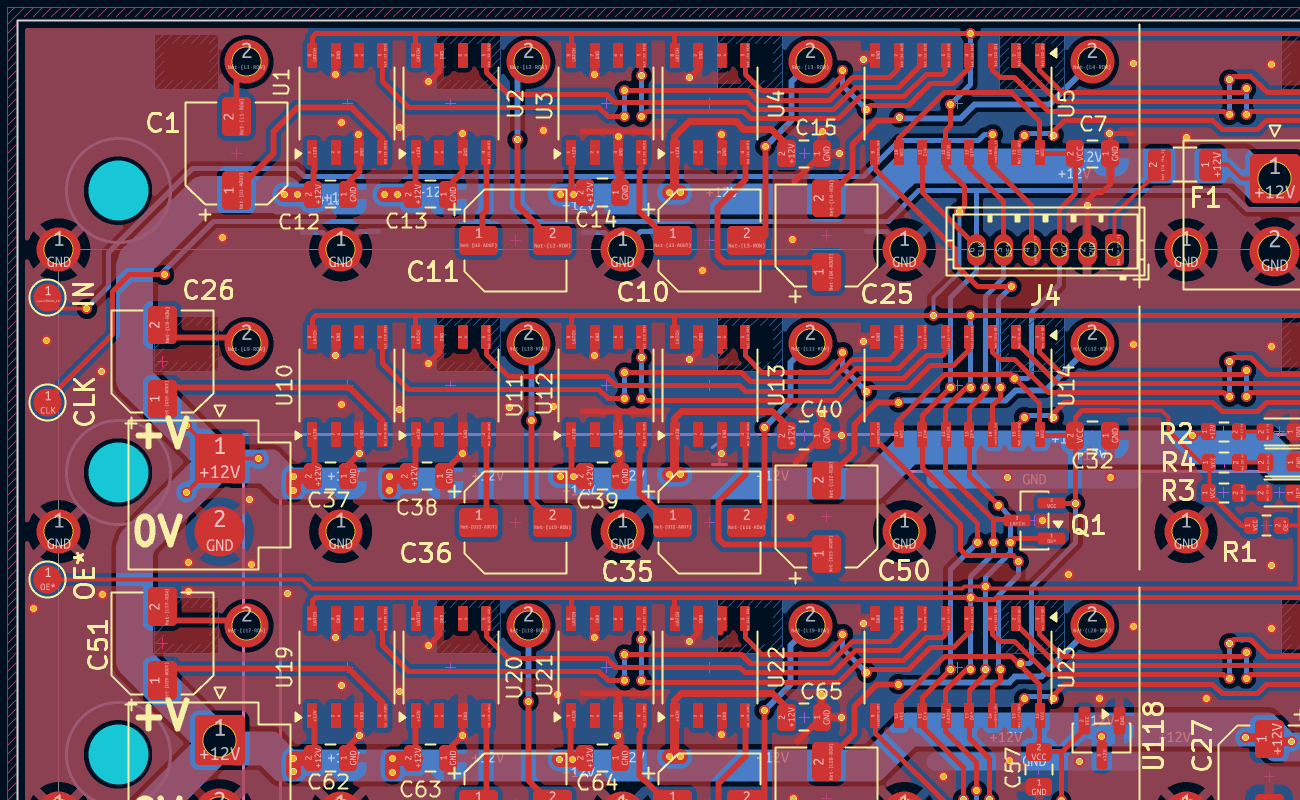
The caps are 47uF, 5x5.4mm, with slightly shrunk footprints in order to fit them in. I added a 3.3V regulator and swapped out the superfluous connectors with test pads at the edge of the board, so we can do little jumps to daisy chain them instead of cables. The 12V is also taken to the JST connector, as we had a spare pin, and we can use it to measure the supply voltage and refuse to pulse if it's too low, both for battery protection reasons if needed, and to avoid failed pulses when the supply browns out. I stuck a polyfuse on that connection, as we might be using a really beefy power supply which got me a bit paranoid.
When they arrived I trimmed another flipdot panel and soldered up the result.
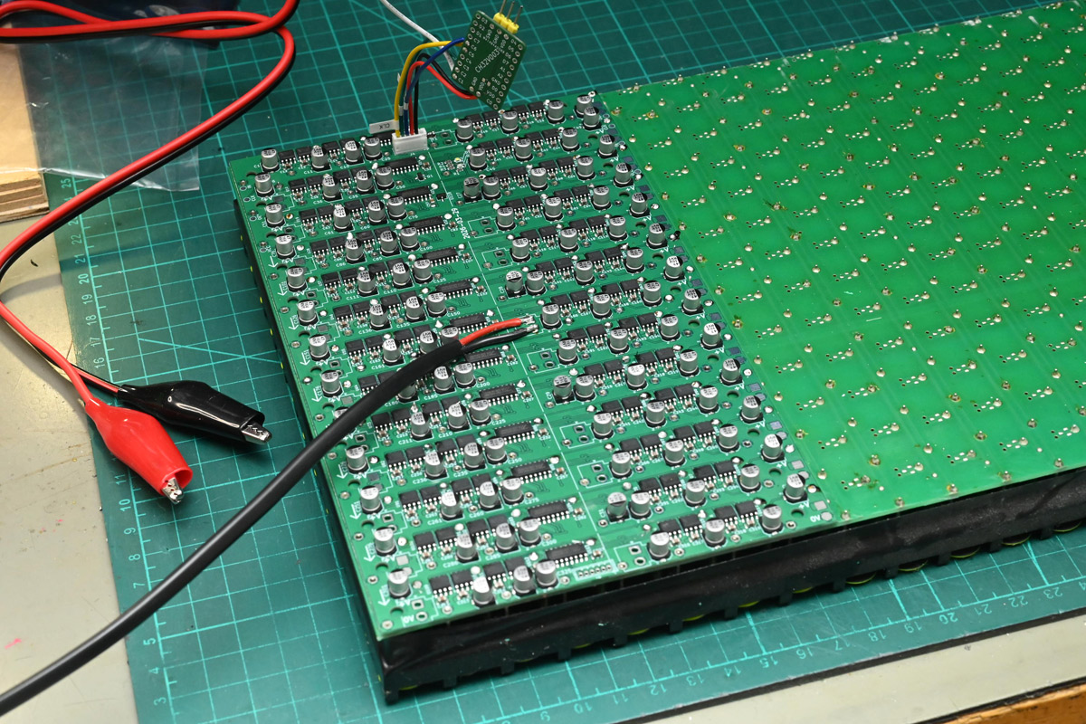
Immediately we got much more promising results, but I'd also ordered a 100-pack of 1000uF electrolytic capacitors, which I planned to solder in as many places as needed. It's only briefly that we'll need hundreds of amps, so with enough capacitance surely anything is possible.
Driving it is one of my CH32V003 dev boards, now pulling 3.3V out of the connector so it can run a test pattern without assistance.
Working my way through an audiobook, I soldered more of the boards into place, and also laser-cut some plywood panels to mount them. The bed of my laser isn't big enough to do it in one piece, but two pieces of 12mm plywood would hold two flipdot panels together. I mounted some brass standoffs strategically over the board.
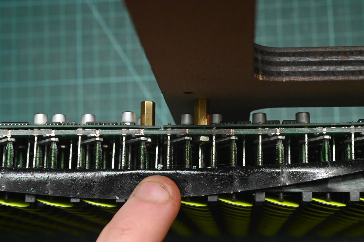
On the first PCB I'd aligned all the holes to avoid any tracks, but for the top edge it was very hard to fit the nut. Here, I moved the top standoff over, making it much easier to fit, but now it intersects one of the row connections. This did end up causing problems down the line, where a couple of them shorted that row to ground, but knowing that can happen is enough to avoid it, as we can peel away or cut that trace when we fit the standoff.
Without the edges, these boards are very difficult to hold without knocking out a bunch of the flipdots. I only realised how much I'd been struggling after I mounted it to the plywood and everything became much easier.
One PCB manages eight columns; there are 28 columns on the panel. I had wondered whether we could link two panels end-to-end, forming a single panel with a driver board straddling them, but given how unwieldy that would be I decided, at least for this prototype, to saw a driver board in half. I'd made sure to keep all of the important bits to the left of the centreline.
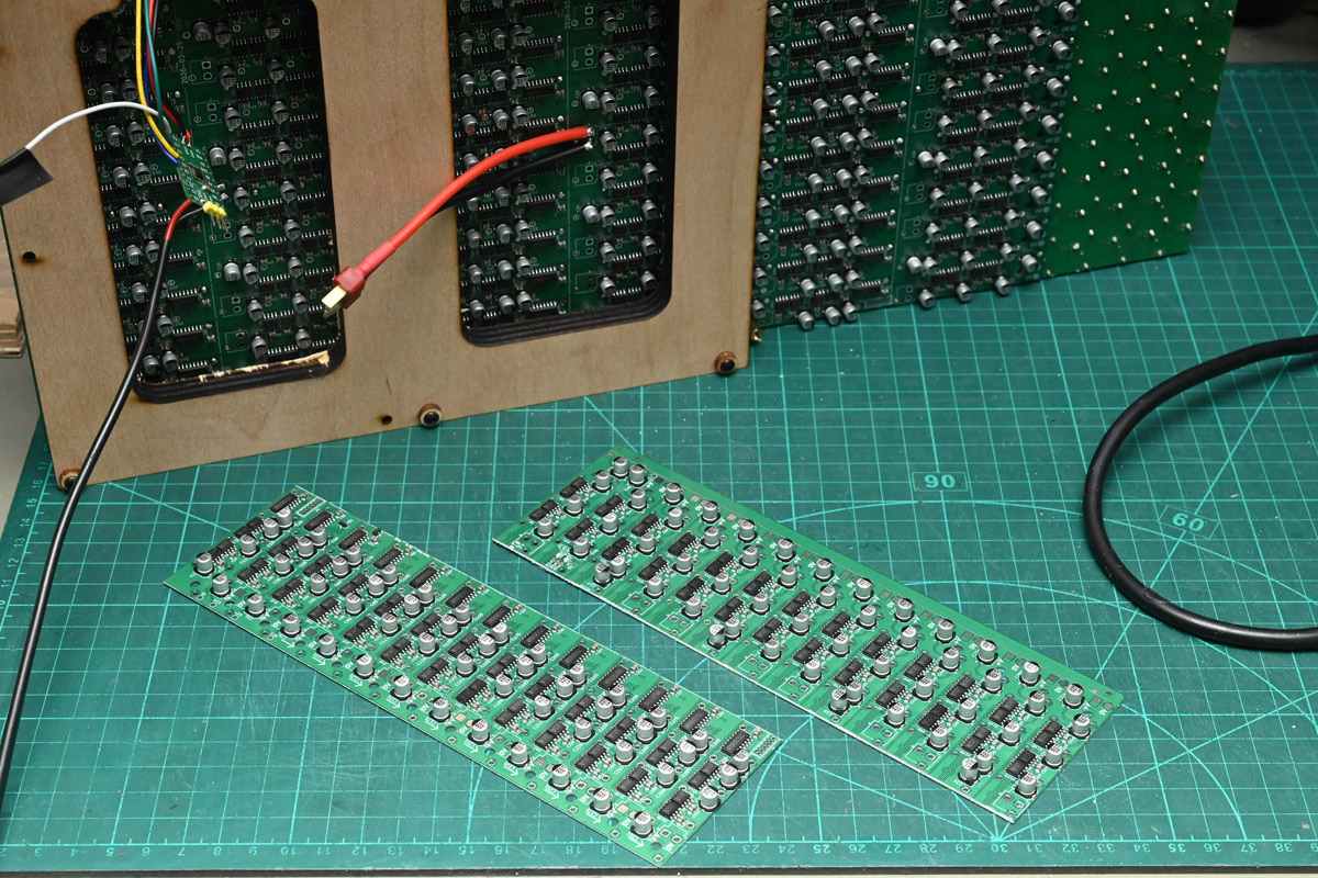
Another reason to cut the board is that we're probably close to the limit on how many shift registers can be chained together. There are 52 on the panel, and with a clock speed of a few megahertz I expect it wouldn't go much further than that. Best to stick a CH32V003 on each panel which can listen to serial data and drive its own group of shift registers accordingly.
Also visible above is a Deans- or T-connector, matching a 3S LiPo battery I'd acquired for testing. Even a cheap small one is able to deliver tens of amps continuously.
The panel comes to life slowly. Many of the dots are missing or don't work, but with gentle coaxing, re-soldering pins where needed, and fitting spare dots, we eventually approach full functionality. For one of the dots the pivot had broken off, but amazingly I was able to find the missing part at the bottom of the box it came in.
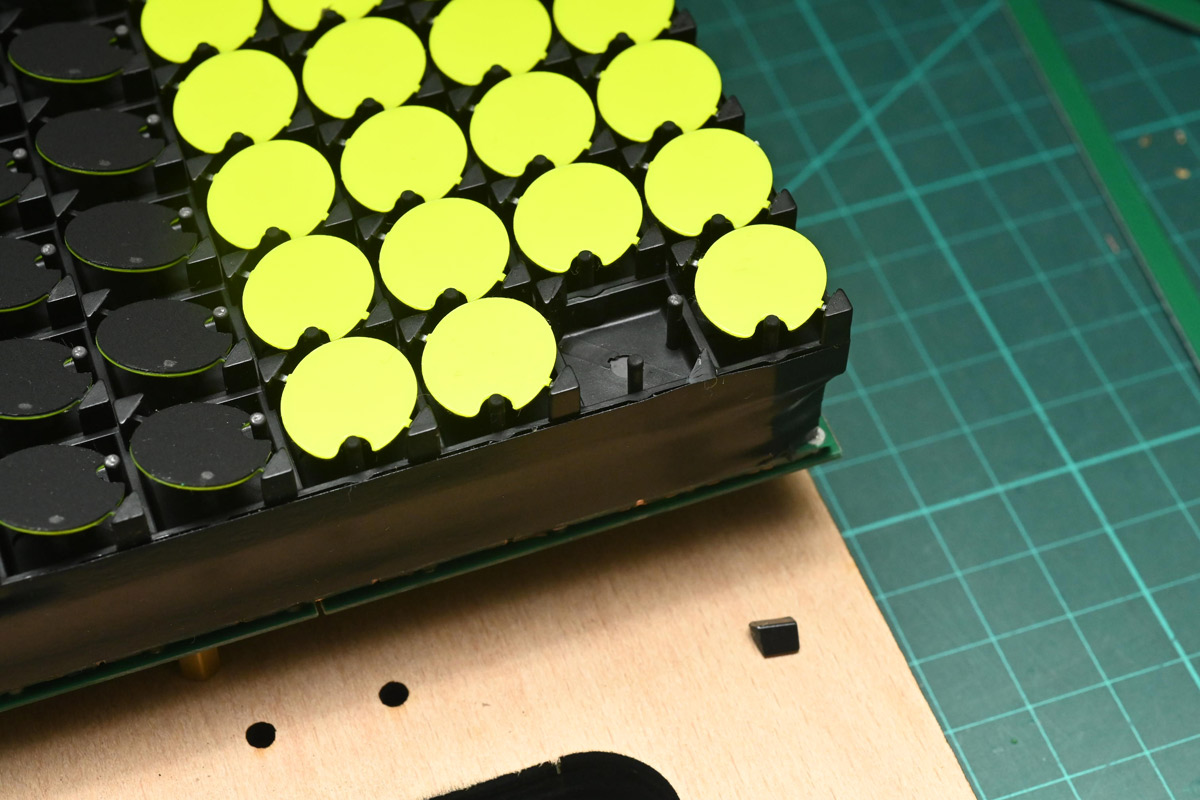
Some superglue set things straight.
Another board was sent through the same preparation process. Best part of an audiobook later and the exciting part was getting near.
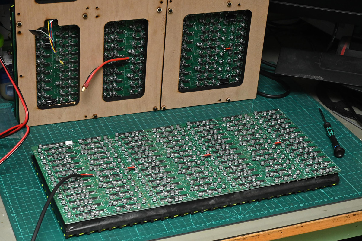
At this point I'd started fitting the 1000uF caps, settling on eight of them per panel. With just a bit more tedious work, the standoffs were fitted, the panel was mounted, and finally with just a little bit of embedded magic, a fluid simulation was brought into being.
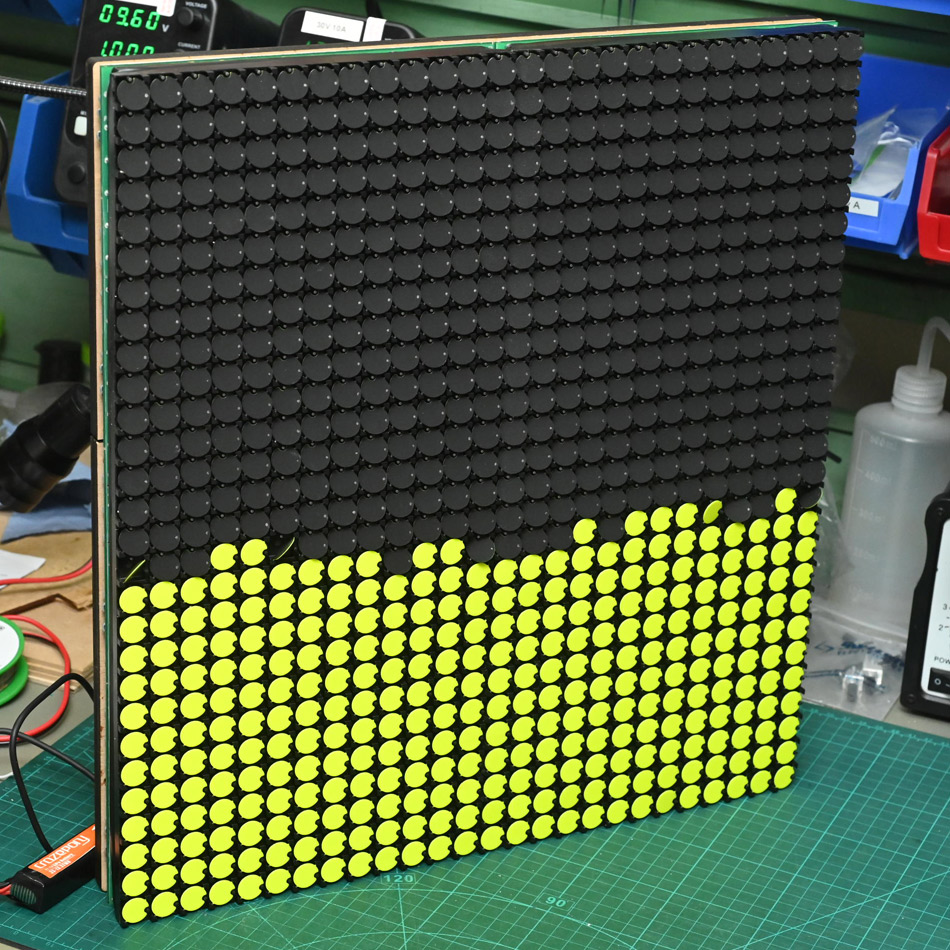
My FLIP implementation was just able to run at this resolution at about 40FPS on a Pico 2. Each panel has a CH32V003 listening to UART and squirting out SPI. The seam between the panels is vertical here, and almost invisible.
With that, we'd proved that we can drive the dots fast, and tile the panels seamlessly, and do it for less than a fortune.
It was pointed out to me that we could have stopped here. We got a fluid simulation running on flipdots, and hand holding the thing has amazing tactile feedback as the dots flip. No one would criticize me for arriving at EMF with just this. But my plan was always to go much bigger.
Mounting Dreams
The two-panel prototype has a resolution of 28 by 26, and physical dimensions of 396mm by 427mm (about 16 by 17 inches). Stacking more pairs in a 2 by 2 square would need eight panels, or 3 by 3 would need 18 panels. That would end up about 1.2m per side (roughly 4 feet). Anything that sort of size is going to be too heavy and unwieldy to manipulate in your hands.
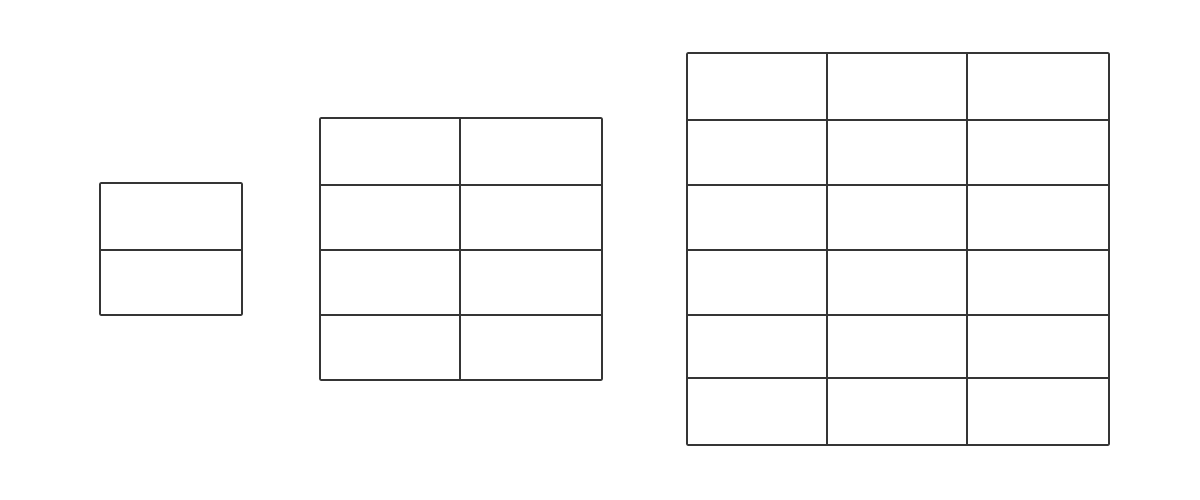
So, we need a mount that will allow the fluid to be manipulated. Initially I planned to build some kind of gimbal, maybe like this:
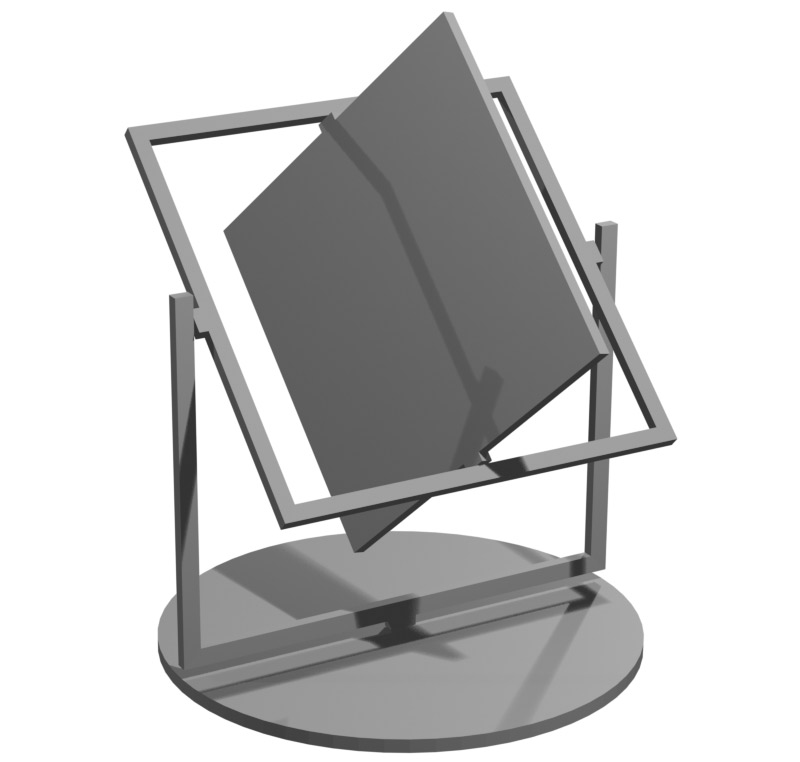
A key motivation is that I wanted the general public to be able to interact with it, and especially to do so in a way that's intuitive and doesn't need me to supervise it. If we welded up a frame from steel, we'd need to be careful that people don't spin it too fast or crush their fingers.
One method of adding damping is to use stepper motors. The motors wouldn't be driven, just connected at each pivot (possibly acting as the bearing) with the coil connections shorted or through a resistor. Using a variable resistance, we could control the exact amount of damping applied. It could even be coupled with series diodes, so that there's no damping at all below a certain speed.
But it might not even be obvious that the panel is something you can grab and manipulate. We'd need clear handles on it. Then again, if there are stepper motors on the pivots, maybe it should just be driven? We could have a control panel in front with arcade-style sticks.
How would it be powered? Adding brushes to each pivot makes it substantially more complex, so my main idea, at least if we forget motorised pivots, was to put a big battery pack on the panel. That would require frequent changes, fine if we just want timed and supervised performances, but no good for leaving it unattended.
A simpler option would be a single pivot, just mount the panel on the wall and let it rotate in one plane. It suffers from the same issues but would be easier to make, and much easier to give a motorised control.
Or perhaps it could be mounted on its back, like a table, with variable length legs?
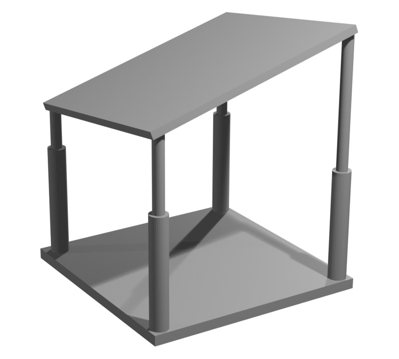
This'd need pivots at the top and bottom of each support of course. Hydraulic cylinders could be unpowered and connected to a shared sealed reservoir, meaning they'd automatically spread the weight. If we're going to do that we might as well go full Stewart platform (six pistons in a delta configuration) and build a control stick mounted on six miniature pistons as encoders.
These ideas are all within my skillset but not really my budget or timeframe. How about something simpler: we could hang the panel from the ceiling (or a frame) by a rope, and then it could swing around. Anyone strong enough could pick it up and manipulate it, others could merely swing it and see the effect. It would probably still need a yoke of some kind rather than hanging it from an edge or corner. If the yoke itself was a pulley, that might give us reasonable range of motions.
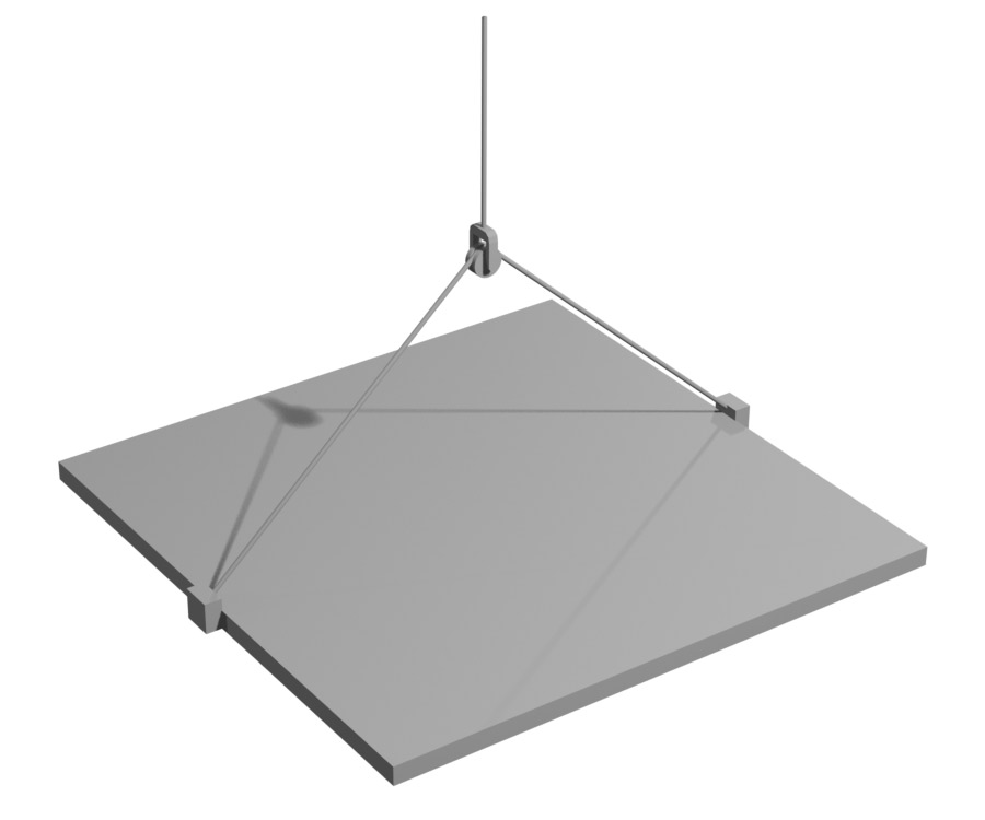
It would need to be perfectly balanced, and still depends on some kind of scaffolding to attach the rope to. And it still could be pretty dangerous if someone pulls it off to the side and lets go.
One final idea I had was to mount the panel on a big squishy ball. Sort-of the inverse of the pulley arrangement, just a soft and gentle blob that takes the weight of the panel as it's tilted about. It would at least be very easy to build.
At this point I wasn't even sure how big I could make it, as I needed to collect more of the panels from Sam. He's a very busy man at the best of times, but round about this point it was announced that he'd been selected as the UK's Eurovision entry. I didn't want to be pestering him in the run up to that, so I thought I'd wait till after, and then next I heard he's just had a baby. I really didn't want to be this annoying guy who keeps nagging for more flipdots, but in the end he was very amenable and enthusiastic about the project. Despite having his own EMF installation to worry about (the fire organ) he let me visit and helped me rifle through the pile of flipdot panels.
The idea of preparing and soldering eighteen panels was already pretty daunting, it'd probably take me most of a month, and with the donor pile being a varied mix it wasn't clear if there even were that many in the size I needed. We did a spot survey, and the majority of the panels were bigger than I'd what designed my driver boards for. There were also some at a different pitch, looked like 10mm instead of 15.24mm. Eventually we unearthed enough of the correct size for me to make my 8-panel display, and I embarked on the mammoth task of soldering them up.
Panel preparations
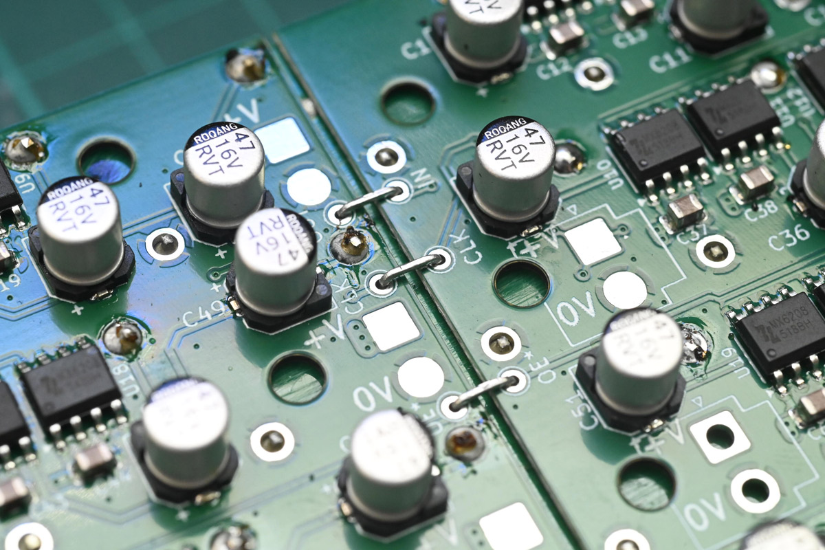
I had planned to update the design with another revision of the PCB, but what with my indecision about how it should be mounted (you might say I was "flipping" between options, hoho) and various other commitments I effectively ran out of time. The boards used for the two-panel prototype aren't perfect but they function, so I ordered more with virtually no changes. About the only thing I did was upgrade the testpads that propagate the serial data. On the two panel prototype, after swishing it about extensively, one of the pad connections had ripped from the board. For more mechanical strength I made them plated holes, into which I could shove bent bits of wire, shown here before soldering:
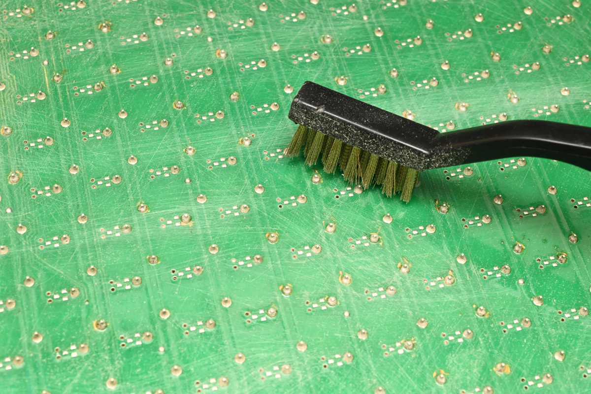
A number of dead pixels cropped up down the line after the prototype had been played with. Re-soldering the connections to them brought them back to life. It was only on the third panel I realised that the boards have some kind of conformal coating, which is why they're so hard to solder to (or desolder). In my attempt to work quickly, not all the connections had properly penetrated the coating and while they initially had continuity, some joints failed after being mechanically stressed.
There might be a solvent that could dissolve the coating, but simply scrubbing the connections with a brass wire brush beforehand worked wonders.
I would have really liked to add a quick way to couple the power connections. There are certainly all kinds of high-current wire-to-board options, but most of them are pretty expensive. The few minutes of soldering we'd save probably isn't worth it.
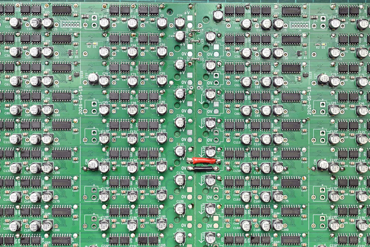
The soldering was endless, but on the plus side here was the perfect time to use up all my neglected reels of solder, the ones with the wrong alloy, or wrong flux content, which annoy me enough that I don't use them for anything that matters.
For the end of each panel, this time I ordered some halfboards that just handle four columns, saves sawing them in half.
Each panel also got standoffs fitted, taking extra care for the top where we now have to drill through a row connection. I made a depth stop for the drill (just a sleeve so that only a bit of the drill sticks out). FR4 blunts drillbits quickly, and I'd bought a multipack of them in anticipation, but actually the first bit lasted the whole batch. To be fair it was only 64 holes in total.
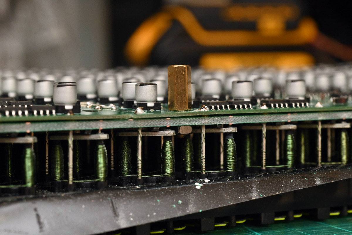
I used tweezers to hold the nut, and a tiny socket driver to tighten the standoff. I possibly could have created a special tool to hold the nut in place. If we do another batch, I think maybe nylon snap-in standoffs would be better, the type you simply poke through a PCB and they lock in place. They'd need to cope with the double thickness PCB though, everything I could find was for 1.6mm boards.
Soldering all these panels took forever, and happened in parallel with the rest of the project. I think it was about panel three I concluded that eighteen panels wasn't going to happen. It doesn't sound like much, only 400-odd joints to solder per panel, but when you factor in all the little details, testing the panels, going back to fix the dead pixels, testing again etcetera, it was remarkably tedious. As I got more practiced, at my very fastest, I managed to prepare two whole panels in one day. All of that was negated when, for a later panel, I soldered the PCBs upside down, and had to spend a whole extra day desoldering them.
Prototype Polish
My mounting worries (as in, worrying about how it will be mounted, though the delays were starting to compound) highlighted the wisdom of having a backup plan, in case the big FLIP is a flop.Dots easily get knocked out, so the prototype needs handles, protective side panels, and maybe a clear cover.
The laser at the hackspace has a bigger bed, so we could cut out the rear panel again in one go. Turning to FreeCAD we managed to cobble this together.
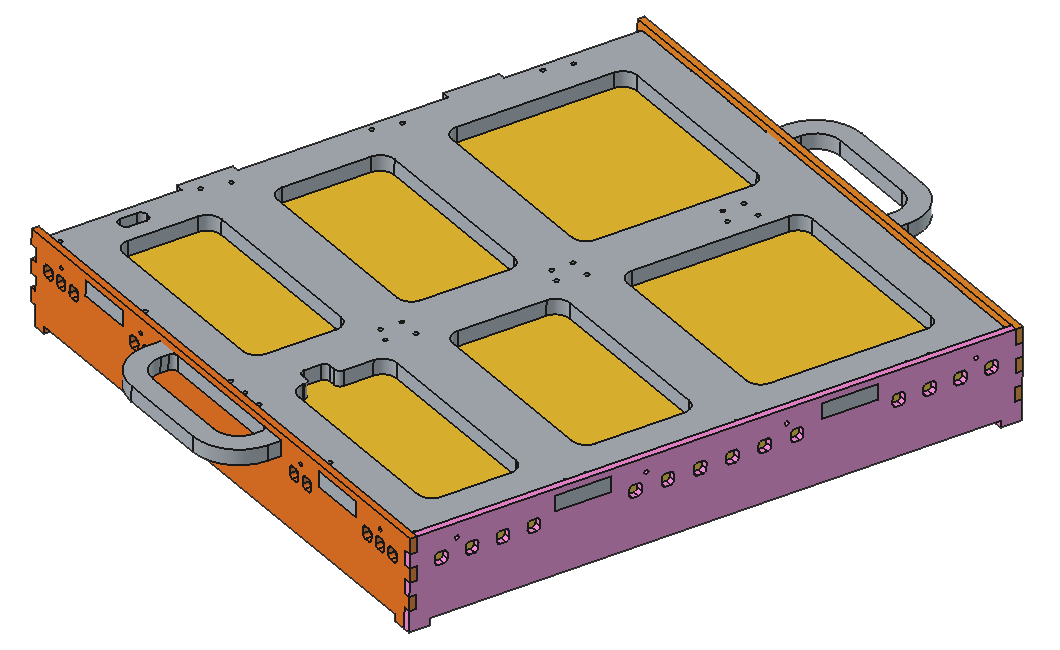
This felt like a project within the capabilities of FreeCAD. It is, after all, just a few bits of plywood with holes in them. But coming from "real" CAD software it's an enormously frustrating process. We have to start using it if we want it to get better though.
There are some fundamental issues with Open CASCADE (which FreeCAD uses) that I understand are very difficult to solve. Things like the "topological naming problem" which is definitely still a problem. But there are also plenty of trivial frustrations that seem to an outsider as fairly easy to fix, like the minor UI problems, or the tedious steps you have to follow to achieve what should be a single click. I won't go on about it, hopefully these annoyances will evaporate soon.
The parts were laser cut...
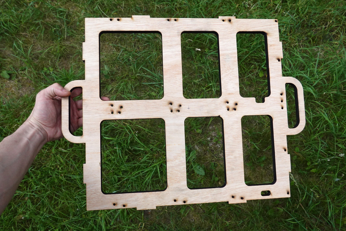
...sanded, given two coats of paint...
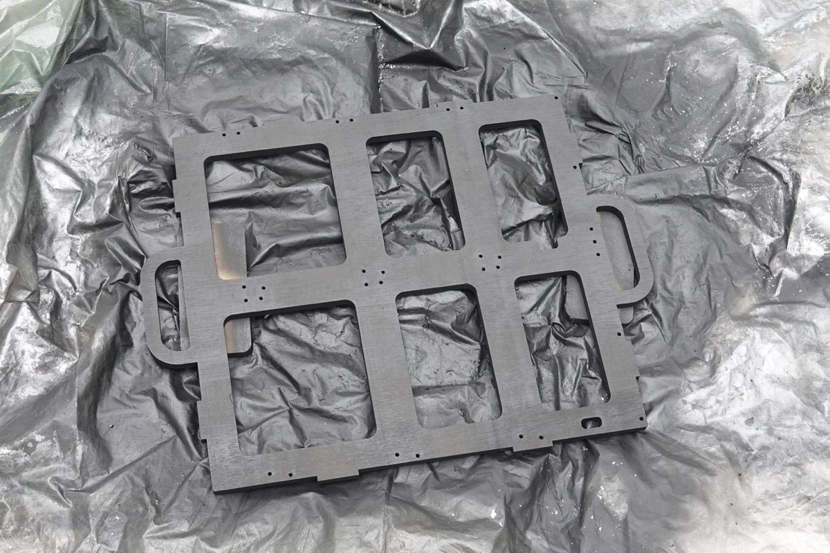
... and test assembled before we start transferring the gubbins.
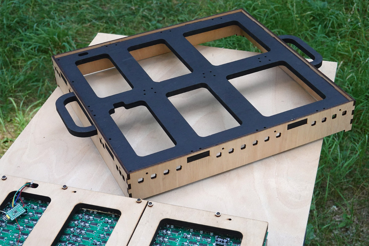
The holes in the sides are for airflow. This thing draws a few amps while running, and that heat has to go somewhere, presumably into the coils. It seemed prudent not to put them in an airtight box. For the same reason, I didn't want to seal up the back, even if the boards are a little exposed.
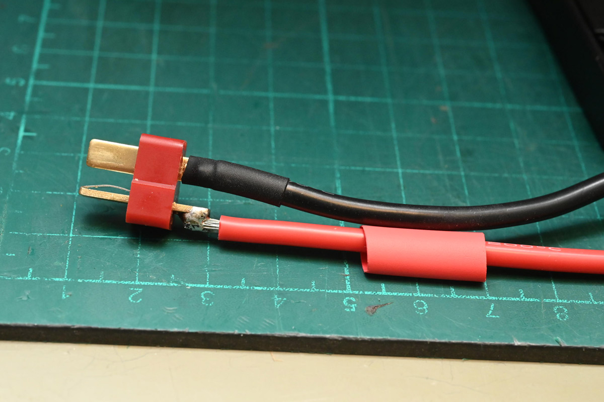
We also cleaned up the wiring, adding a power switch and nicely crimping and heatshrinking everything. I got some slick silicone cables, here we've soldered up the Deans connector.
Some more painting, careful dismantling and re-assembly, and this prototype was starting to look ship shape.
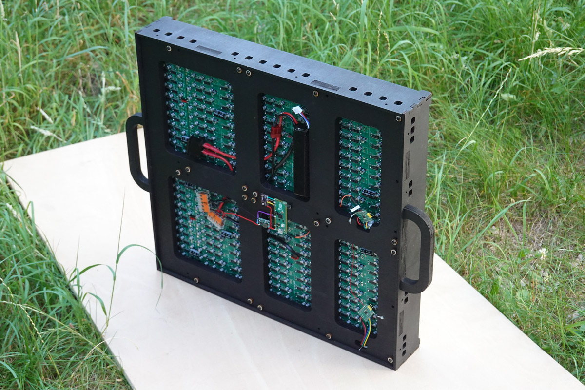
The LiPo is held in place with velcro, and all the important parts are held in place with screws or wire ties.
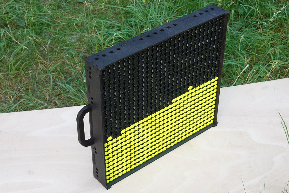
To finish I added some feet to the back so it can lay flat without crushing the electronics, and installed an acrylic sheet to the front, aligned to those protrusions in the corners. I spent ages fitting tiny magnets round the perimeter so the acrylic sheet is removable.
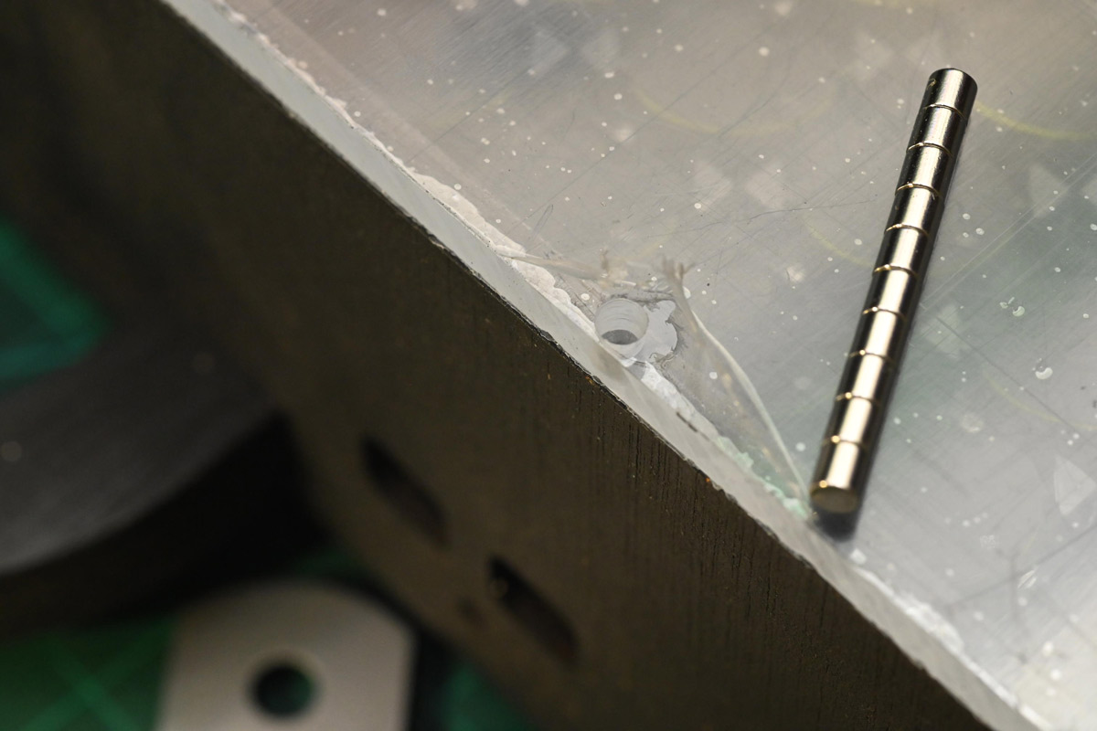
The magnets get glued into the holes, and matching holes with magnets are made in the plywood.
However the acrylic sheet ruins the sound of the flipdots, muffling them until the fun is gone. At least now we know not to bother when it comes to the big display. Another interesting effect, as I peeled off the protective film, the static charge played havoc with the dots, overpowering the magnetic attraction. Even after wiping it with a damp cloth it seemed to impact their performance.
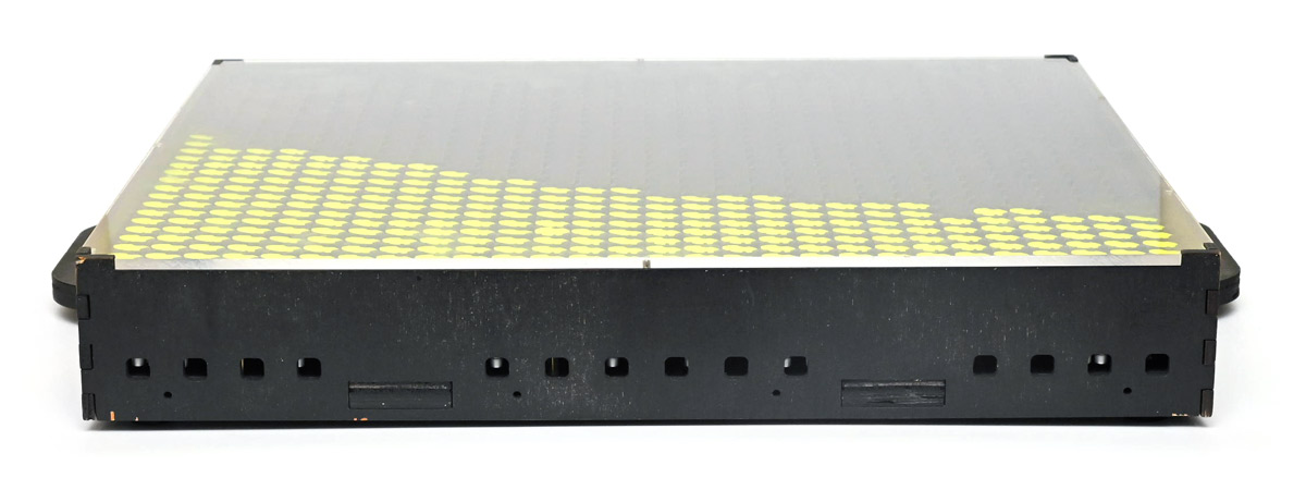
The cover was very useful for protecting it in transport though. Pictured here upon return from EMF, with scuffed case after plenty of usage:
Framework
I've had great success ordering parts laser-cut out of sheet steel. There's a minimum order cost, but beyond that it's very cheap, hardly more than the base cost of the steel. With some thought, we can add tabs to the pieces so they slot together neatly before welding. It's a very fast and accurate way of building really strong and durable constructions.But it comes with a lead time, and with the drop to only eight panels, I realised I could do the whole thing in plywood in one go at the hackspace. I scaled up the design of the prototype.
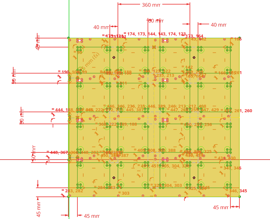
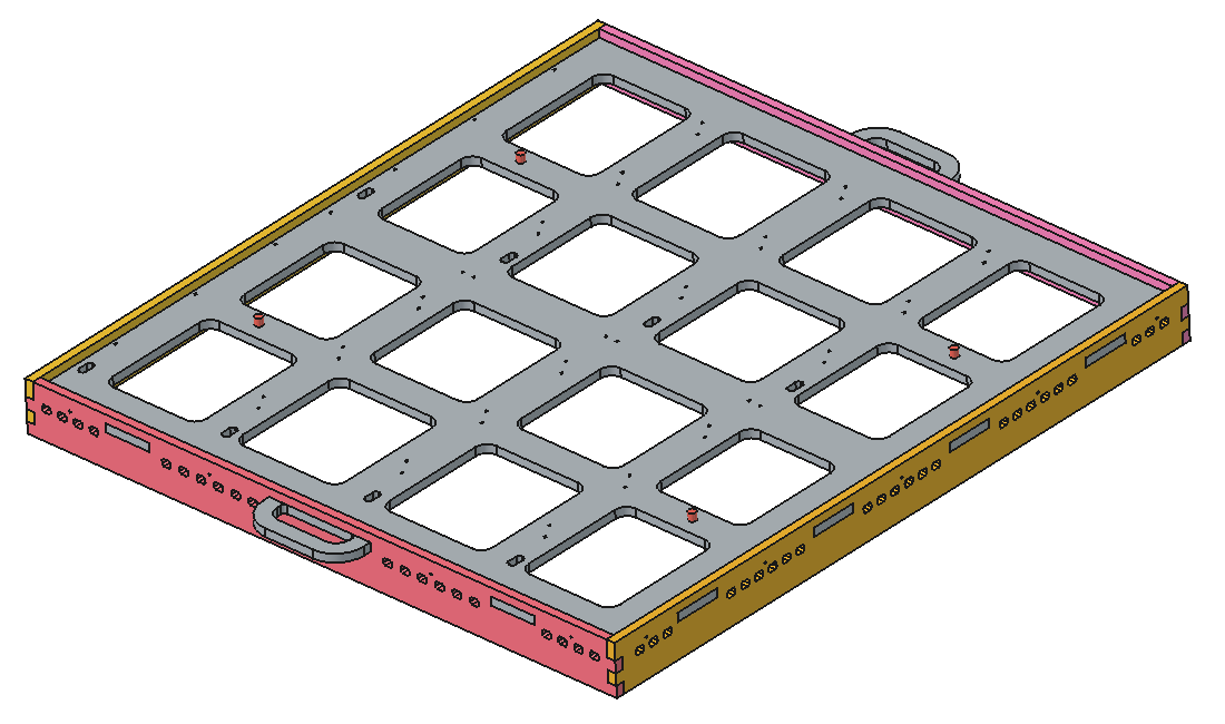
Ah, FreeCAD. So clear. The red cylinders mark a potential hole pattern for mounting it. Not shown are the imported PCB outlines we bind the hole patterns to. The grid pattern is a compromise between strength and exposing the circuitry, for air cooling and all those electrolytics we plan to install.
It's much cheaper, and much much faster than sending off for it, but my plywood comes with the downside of being warped. In retrospect, I should have started with higher quality stuff. After cutting the stock to fit in the machine, I had to raid the welding area for as much scrap steel I could find, to weight it down in the corners. If I'd cut it a little bigger we'd have had an easier time, here I had to triple check the head wasn't going to collide with a pile of steel.
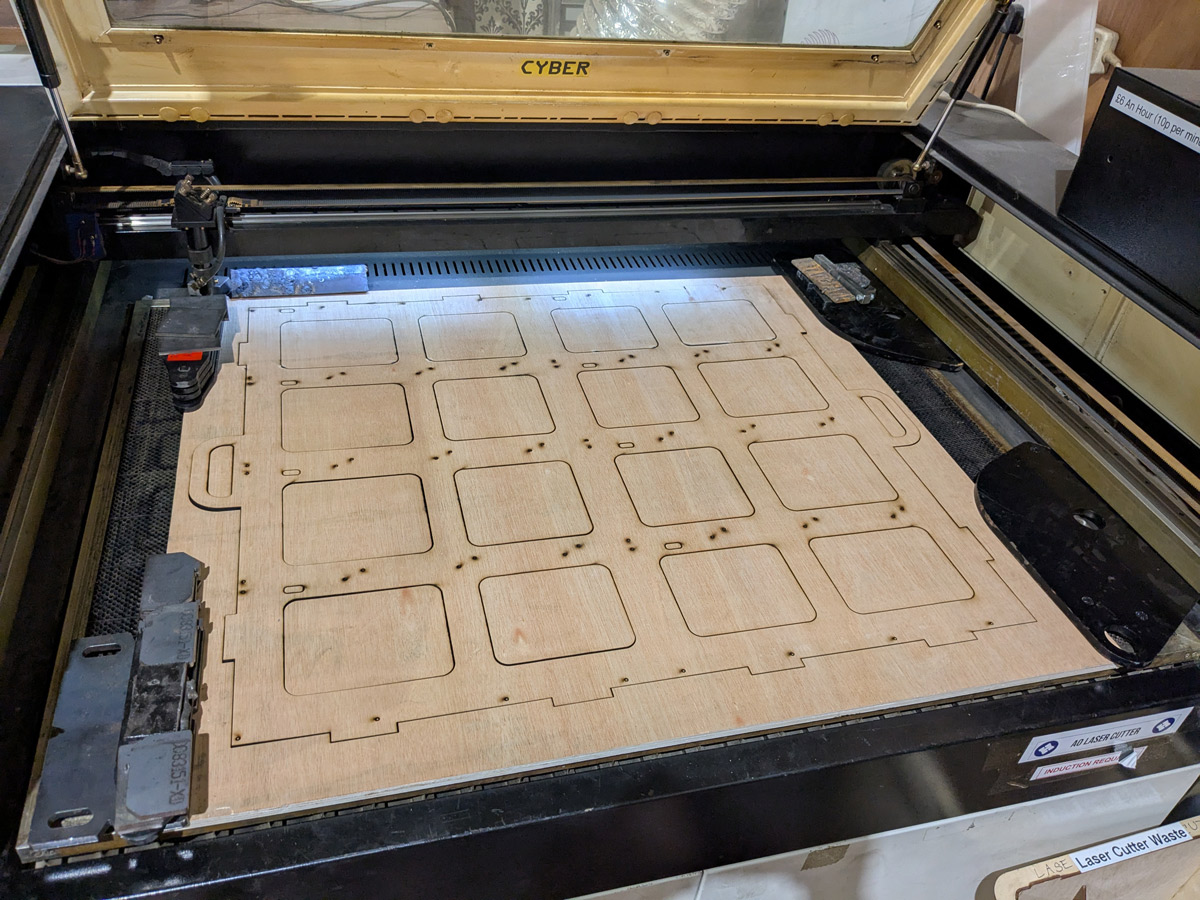
That's probably the biggest single cut I've ever done. The optics aren't great on this machine, and the progressive error of the beam means it cuts worse in certain areas. Couple that with the warped plywood (meaning inaccurate focus) and the only way to guarantee a complete cut is to set the speed real slow. I think it was 57 minutes of nail biting. If you nudge anything the whole thing is ruined.
I set the warp to be concave, so weights could hold it down at the edges, but I put no thought into how this would affect the flipdots. I should have set the design so the flipdot panels are crushed together, rather than spread apart which might lead to a visual discontinuity. Oh well. Fitting the side panels counters a lot of the warp anyway.
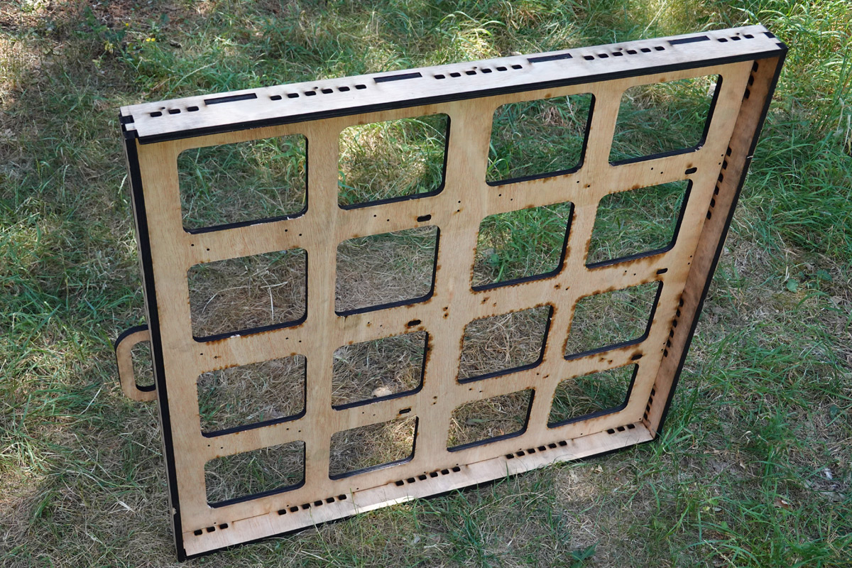
The underside splodges are a sign the laser dwelt too long in those areas, but in other places it didn't fully cut and I had to finish off with a chisel, so overall I think I got the speed and power about right. It all gets hidden by two passes of sanding and painting anyway.
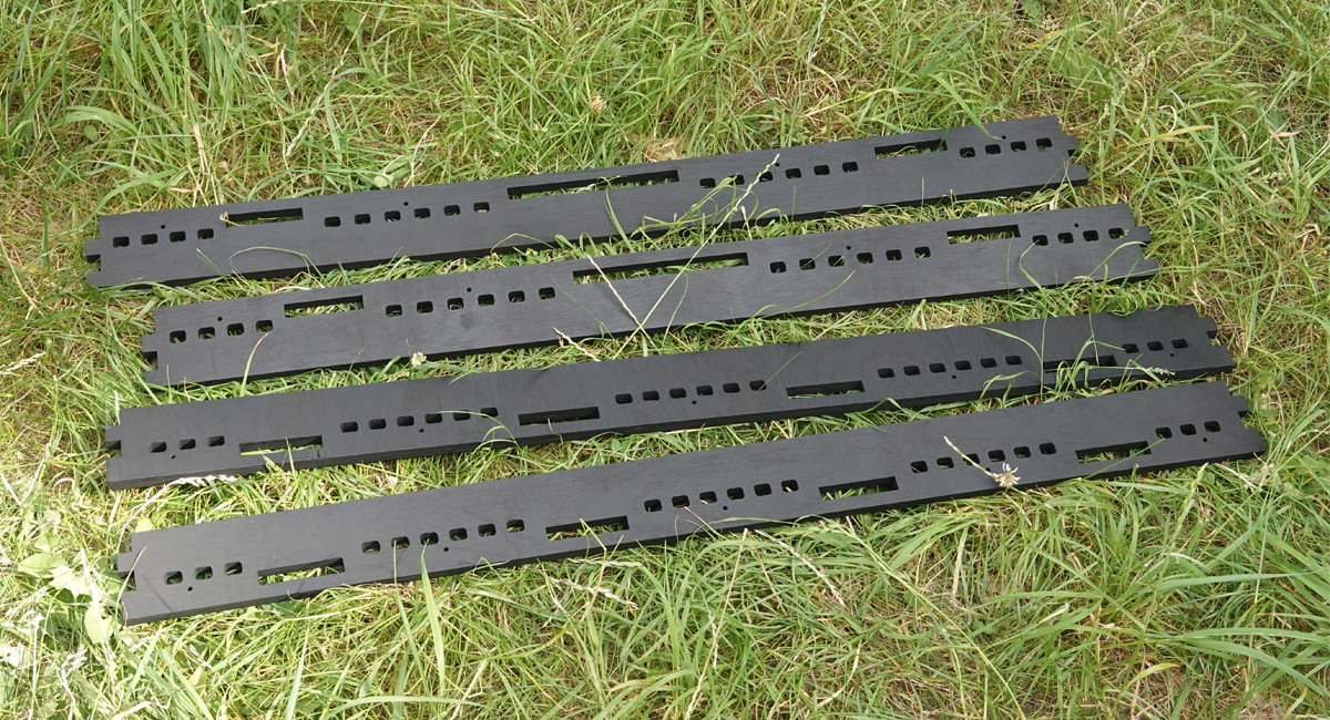
I still carried a vague hope of gimballing it all, but with only a few days till the event an articulated fixture was looking unlikely. Keeping my options open I added four M8 mounting plates in an approximate VESA pattern, to fit an off-the-shelf TV mount. The backup plan was to keep the panel static and put a joystick in front which would control the direction of gravity.
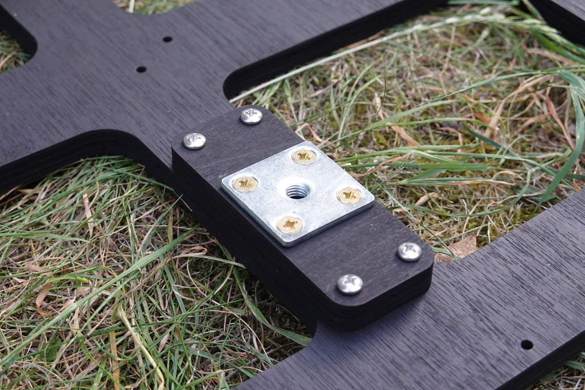
There are plenty of M8 plates available as table-leg attachments, but worried about the strength of the plywood I laser-cut spreader pieces that save us having to make big holes in the frame.
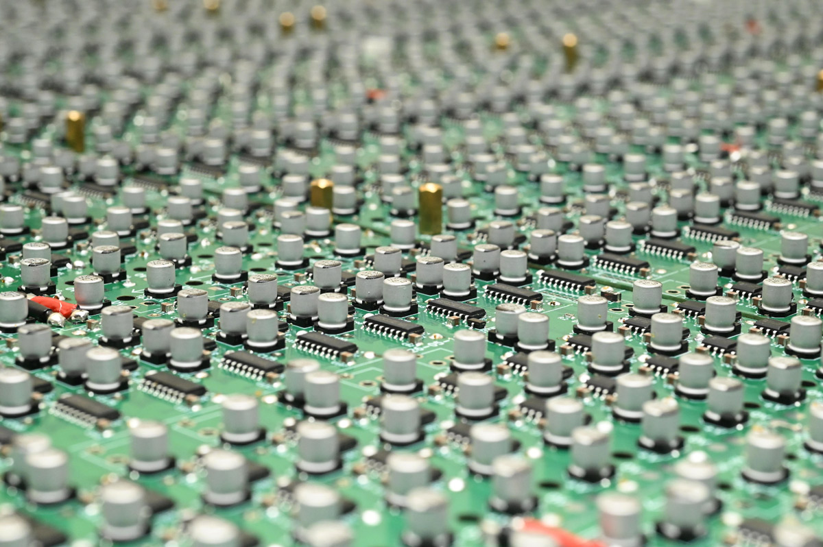
With that we can start arranging all the prepared panels for the grand assembly.
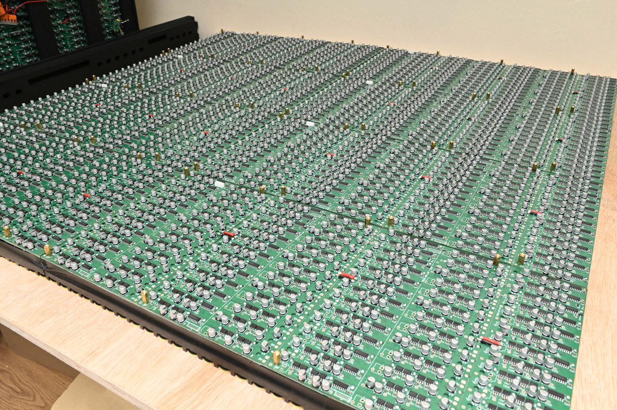
Too big for my desk, another not-quite-flat slab of plywood serves as the surface.
There's a reflective moment in projects like this, where the accumulated time sunk starts to become tangible, the hundreds of hours of soldering spread out on the table in front of you, and you wonder, is it going to work?
Thus began an extended session of awkwardly maneuvering the frame and endlessly installing M3 bolts with laser-cut washers. The side panels are then fitted, along with the VESA mount rails that make it easier to pick the whole thing up.
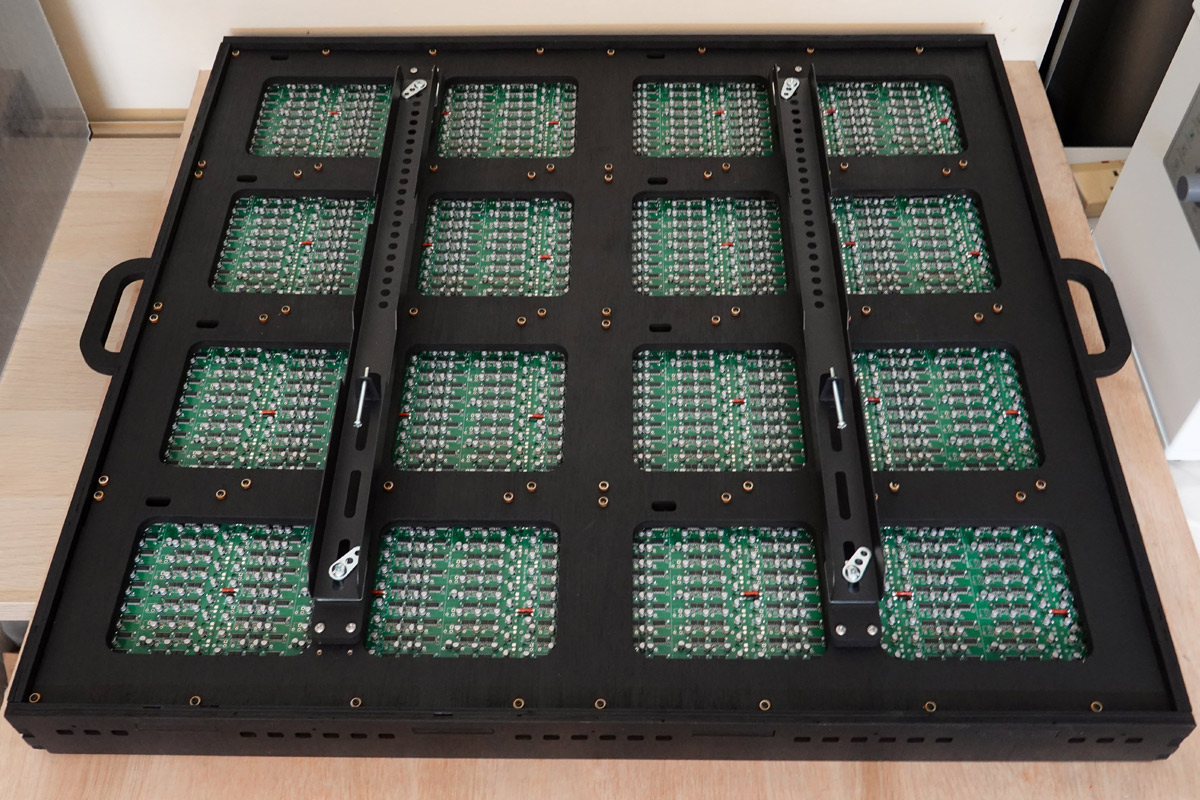
It weighs about 15kg at this point. The side panels are just a press-fit, though I'd planned to screw them in place.
While it appears to be a thing of beauty, there's a lot more electronics to do before we can test it.
Decoder Boards
On the prototype, the shift registers were driven by hand-soldered microcontrollers listening to UART from a motherboard. Scaling up, with more pixel data and physically longer cables, something more resilient is in order. Now that we've dropped to just eight panels, RS485 might be overkill, but with thousands of coils pulsing thousands of amps... a little bit of overkill can't hurt.With asynchronous serial data, as a general rule, the faster the baud, the shorter your maximum cable length. RS485 is a differential signal that gives you vastly more headroom than a single-ended equivalent. The only downside is that you need encoders/decoders at each node. There are plenty of alternative ways of doing it, sometimes it makes sense to daisy-chain panels, with each one re-transmitting to the next, much like how addressable LEDs work. Or, have separate groups of serial data (referred to as a "universe" in the DMX world) so each group carries only a fraction.
My preferred method is to give each board an ID, and transmit all of the data to all of the boards. Not only does this mean we can route the cable in whatever order we like, it means we can easily sync the frames. The data consists of a header, a big block of pixel data, and a footer. Each board decodes its chunk of data as it arrives, but only latches the shift registers at the footer.
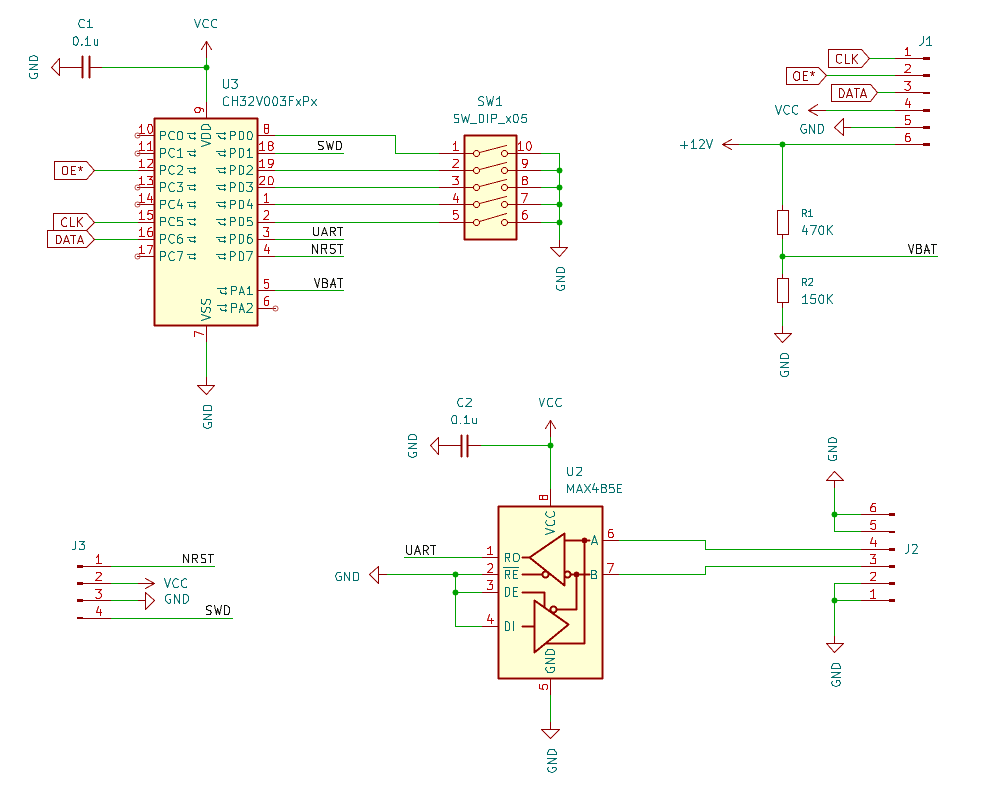
A DIP switch lets us set the ID (up to 32, you never know) and the 12V line is monitored, via a divider, so we don't pulse if the supply drops below 9V. This is both for protection if we do run it from a 3S LiPo, and to avoid failed pulses that demagnetise the dots. It's important to give this hysteresis, so the low-voltage cutout latches until the supply climbs above, say, 9.5V. The VCC line is from the 3.3V regulators on the panels. Note that there are variations on the MAX485 decoder chips, not all of them work at 3.3V, a lot expect 5V.
A full frame of data is only about 3000 bits, so 1 Mbaud is fine. A nice thing about CH32 parts is that they're pretty accurately trimmed from the factory, I've not had any problems decoding UART with them, unlike AVR chips, which often misbehave without a crystal. There's enough headroom that we don't even need proper twisted pair, my plan was to use a ribbon cable and clamp IDC plugs anywhere we need to tap into the data.
It's tempting to try to do the bit-shifting on the decoders, to offload whatever's driving it. It's particularly awkward as the second column of panels doesn't align to the 8-bit data. But trying to figure it out before the thing's assembled is far too mentally taxing so it's best if each decoder simply snorts a block of data and squirts it out unmolested.
In my haste I forgot to add a status LED and immediately lamented it. I hand soldered one onto one of the boards. I also failed to really think through where the boards would sit. The JST connectors were meant to make things simple, but not having cables of the right length complicated the situation, and eventually I cut some pre-made cables and soldered them in place at the decoder.
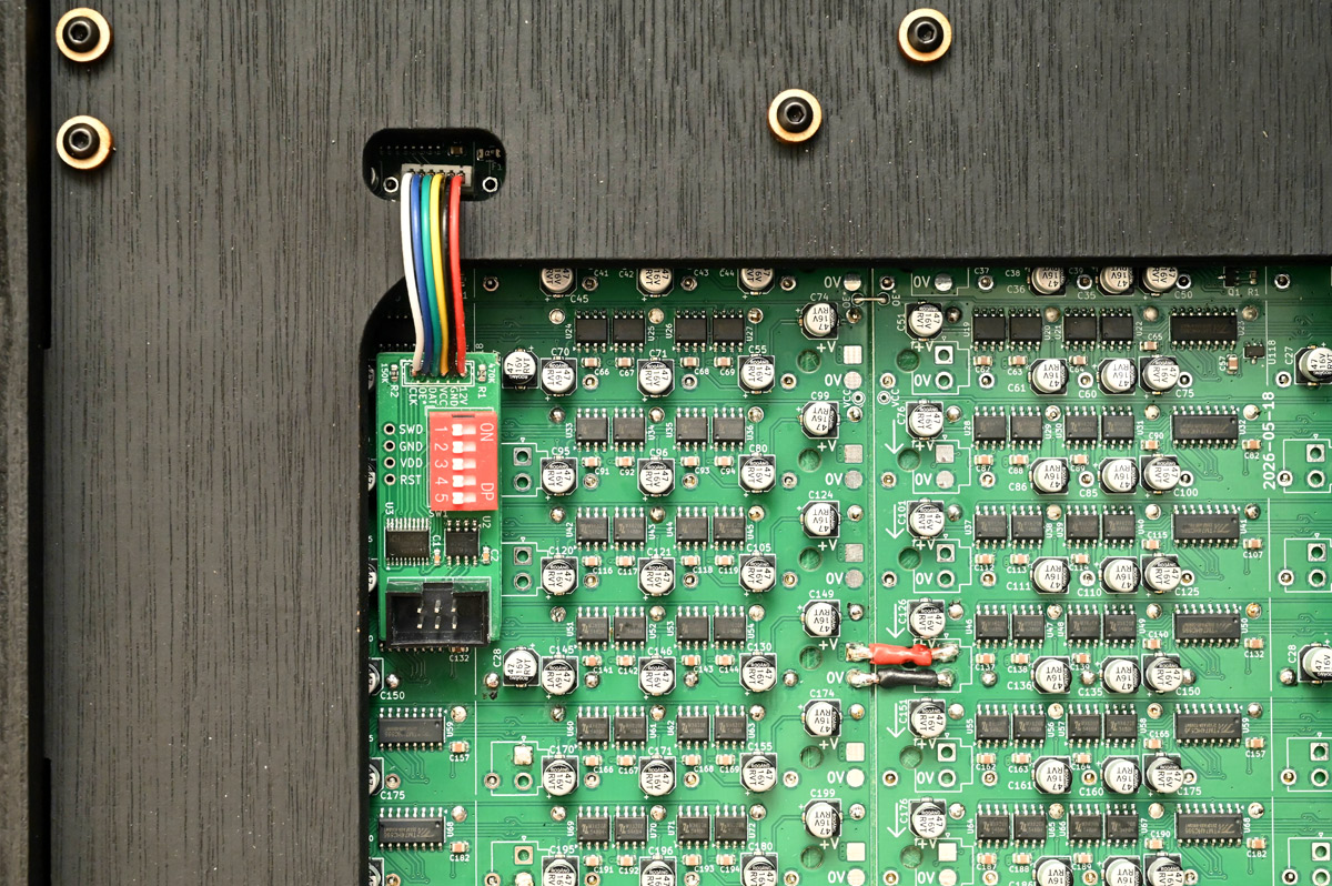
It would have made more sense to connect the decoders to the panel before fitting the frame, and then skip the holes in the plywood entirely. I had thought about using surface-mount header pins, with matching socket on the decoder, but again, we had no time for such fancy solutions.
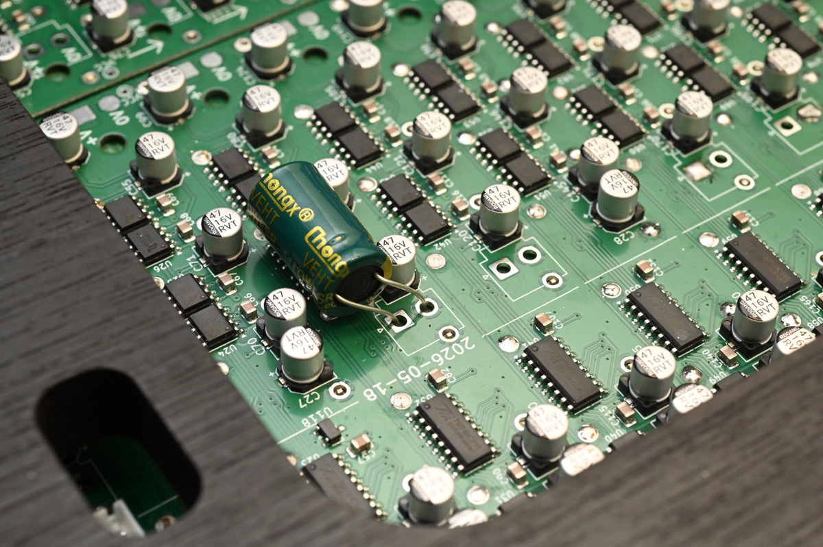
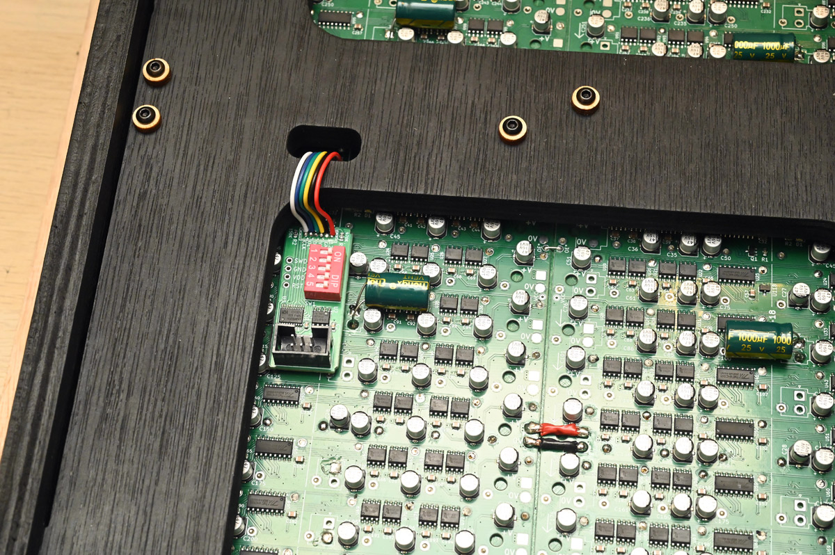
With the frame and decoder boards ready, we can start fitting the big 1000uF caps, tediously bending their legs to avoid obstacles.
The boards were then wiggled into place and stuck down with VHB tape.
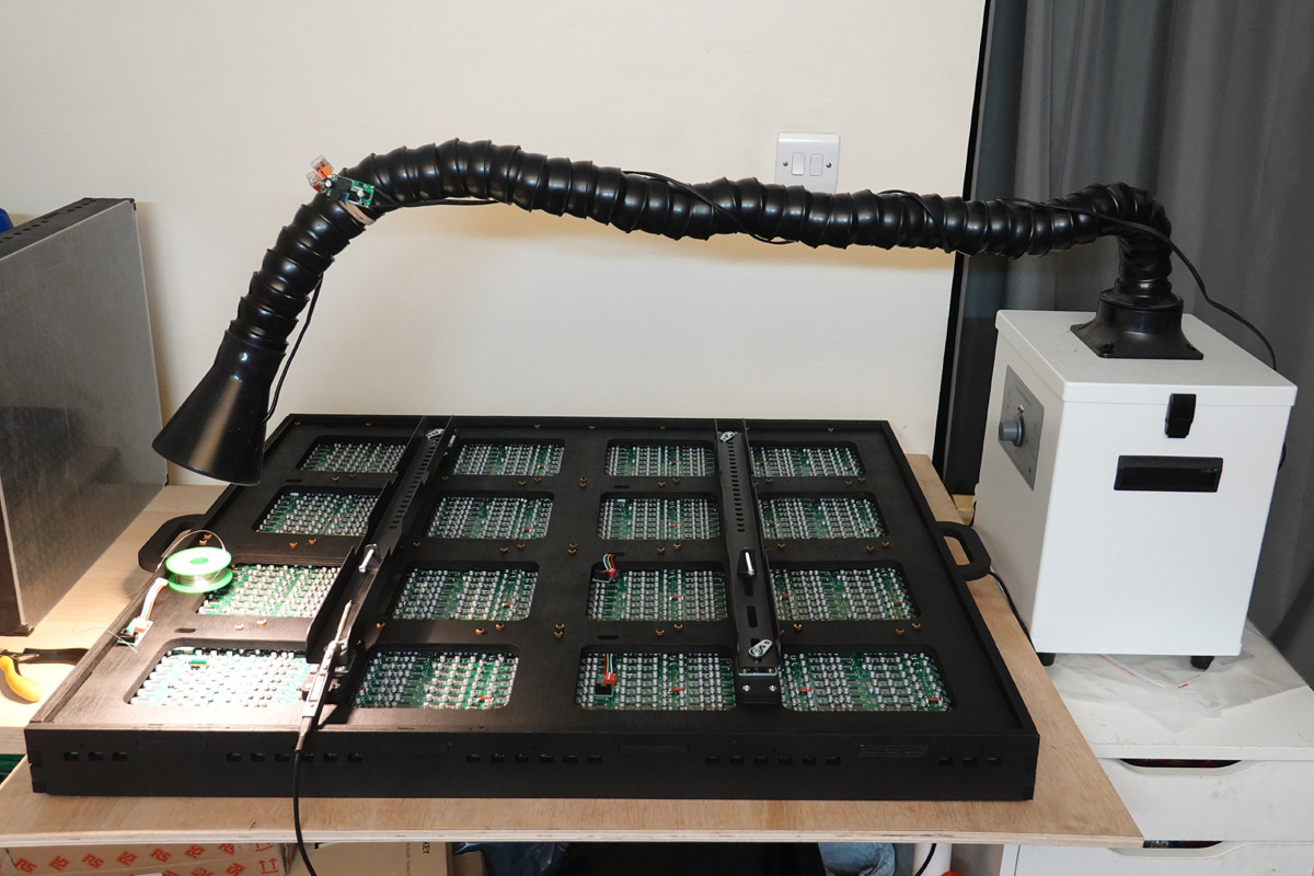
There was so much soldering still to do, that I transplanted my illuminated fume extractor to get full coverage.
Power supply
There's a vast range of high current DC connectors available, but I limited the search to types commonly fitted to batteries in our ballpark. These 5200mAh 3S LiPos are fitted with XT60 connectors (There is an XT90 connector for even higher currents, used on things like electric bikes). 80C means they can deliver 416 amps continuously, or in other words, can be drained from full to empty in just 45 seconds. For testing our half-finished panel they were very useful. They even conveniently clip into the mounting rails, a pleasing coincidence.
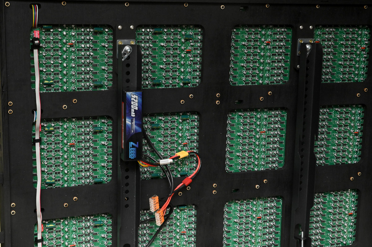
A looming question was whether the inrush current was going to be a problem. With nearly half a farad planned in total, powering on will involve an enormous surge. Nothing that LiPo can't handle, but maybe an issue for our mains supply. Unprotected batteries won't care, but if there are fuses in the supply circuit the inrush current can cause them to blow before it powers on. There's ways to deal with it, usually by warming up the circuit first via a resistor, then switching in the full current. That could be via a relay, or a mosfet if it's suitable. You can even use a single mosfet and an RC circuit at the gate, so it switches slowly.
After some experimentation and extrapolation, I decided that at this scale we're probably fine. The average draw of the whole panel in use is going to be around 10 to 15A, and the boards won't start pulsing until the supply has stabilised. Another factor in our favour is that the capacitance is distributed, and the inductance of the power cables will filter a lot of the spike. Worst case, we can split the power rails into groups and give them separate switches.
I ordered a 12V mains power supply rated for 40A. The first thing I did was adjust the output up to 13V, for slightly better performance from the dots, especially if there'll be losses in the cable. And in case someone trips over the cables, risking a loose live wire, I wanted proper connectors instead of screw terminals. That means building a little box with panel mount sockets.
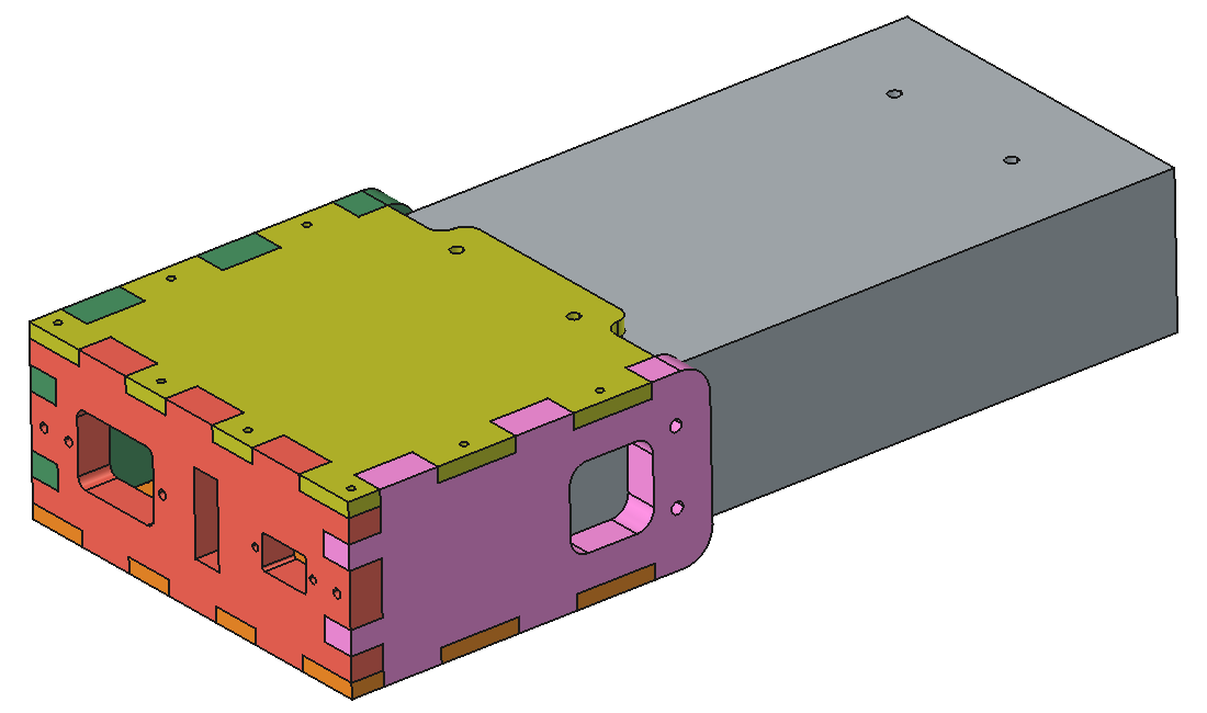
We're careful not to block any of the vents but otherwise cranked this out at breakneck speed. Even restricted ourselves to only one coat of paint.
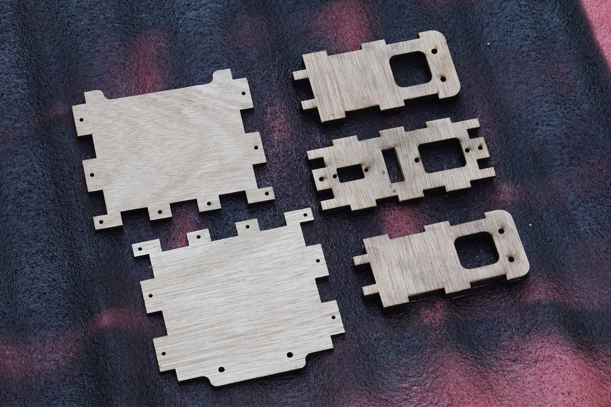
Connections were soldered/crimped and heatshrinked.
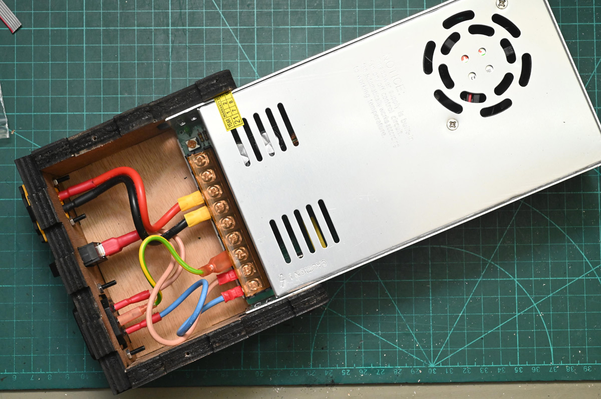
I'd originally planned to sit this on the floor somewhere away from the installation, and make up a long DC cable. I bought male/female XT60 connectors and enough 12AWG silicone flex cable to keep it a few metres away, but then I realised we might as well just mount it to the back of the panel and save ourselves the bother.
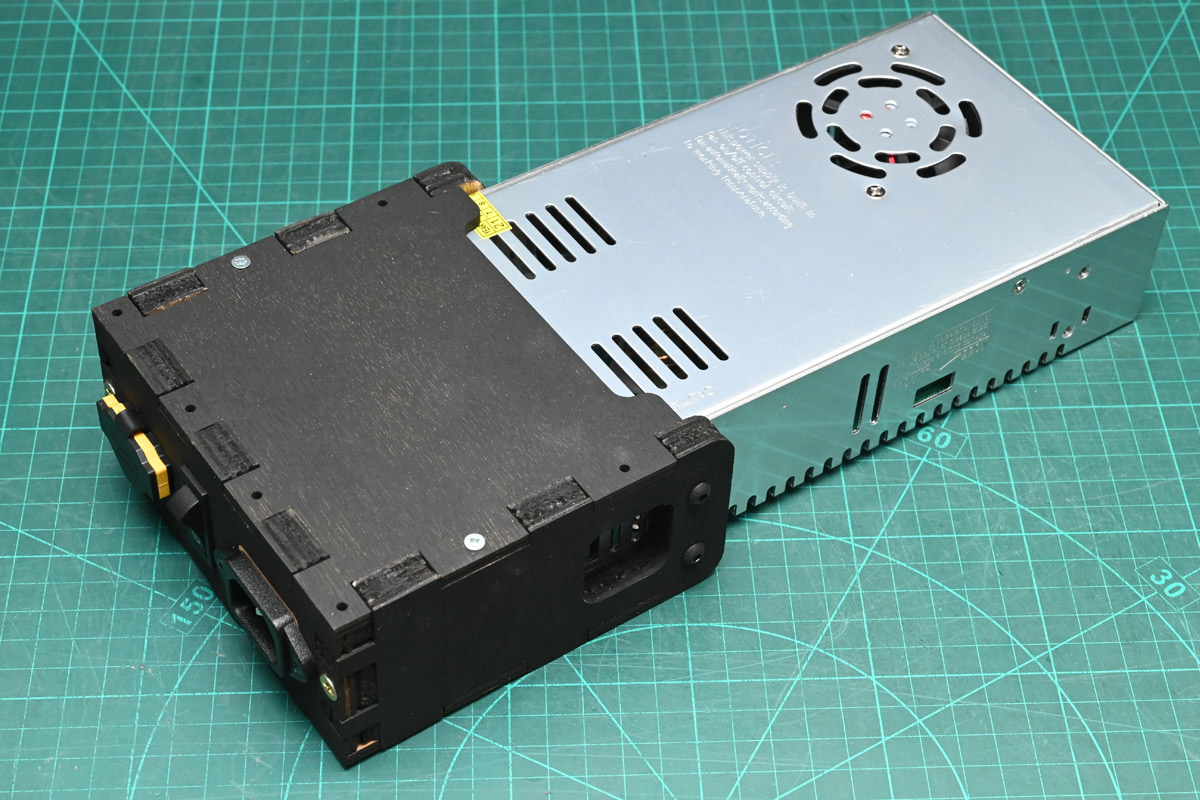
However, the PSU has a fan, and if we mount it right up on the panel, that fan is actually deeply annoying. It has a loud whine, and it spins up and down as the load on the display changes. Most people might not have noticed, but one of the main reasons we're doing this is for the sound of the flipdots, so it's not something I want to compromise on.
Pulling the supply to bits, the fan has a standard size, but not much wiggle room with where it sits. We can't fit a bigger fan, but we can replace it with a better one.
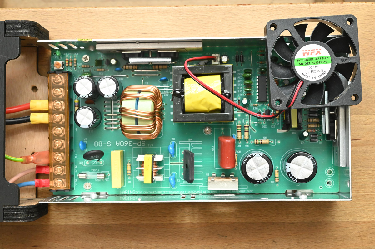
I ordered a "Noctua" brand fan, very expensive, but supposedly the quietest you can get, with engineered blade design and superior bearings. Annoyingly, the old fan isn't driven by PWM but some kind of current control circuit, with the terminals reaching 30V with no load. The Noctua fan seemed to cope. I did consider if it might be better to run it straight from the 13V, then at least it won't have those noticeable speed changes.
While quieter, the new fan had perceptibly lower flow. It would be just my luck if I muck up the cooling, the power supply blows up and the whole installation is a dud.
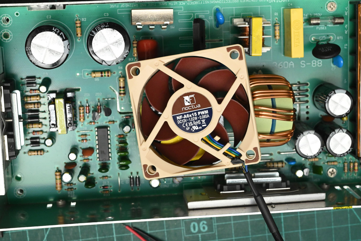
Whatever – I rolled with it and also stuck some passive heatsinks on the case where the main transistors are bonded.
Joystick
I'm aware of how long this writeup is getting, but the joystick could have been an entire project on its own.
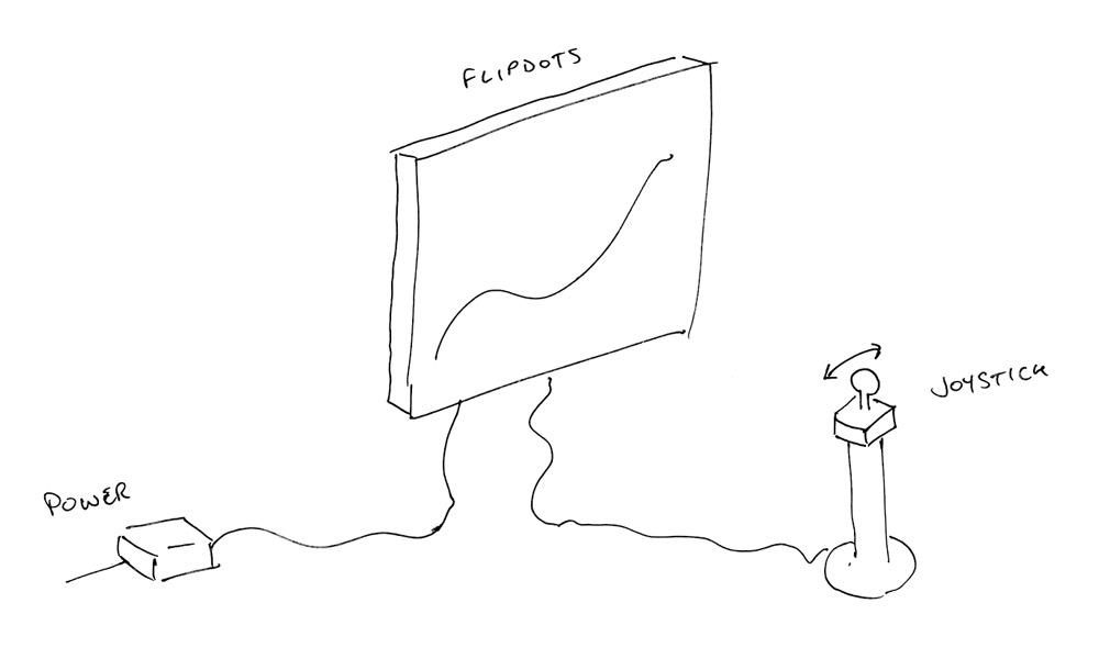
Statically mounting the panel as an easier option than the gimbal occurred to me only a few weeks before the event, which sounds like plenty until you realise nearly all arcade style joysticks are essentially D-pads, with just four microswitches instead of analog output.
I found a bunch of projects where people had converted off-the-shelf arcade joysticks to be analog. One of them looked promising but they hadn't released their CAD files before disappearing from the internet. Another was a commercial offering replacing everything with hall sensors and a big toroidal magnet attached to the underside of the stick. We might have been able to cobble something together, eventually, but the joystick was meant to be the "easy" option. Eventually I found a potentiometer-based joystick from the brand SJ@JX, from just one seller on Aliexpress. I ordered it right away, but postage from China meant a very stressful wait.
I was able to plan and order the rest of the pieces before it arrived, along with a backup idea we won't go into, in case the Aliexpress option failed to turn up or failed to work. When it finally arrived, we embarked on one of the maddest dashes yet.
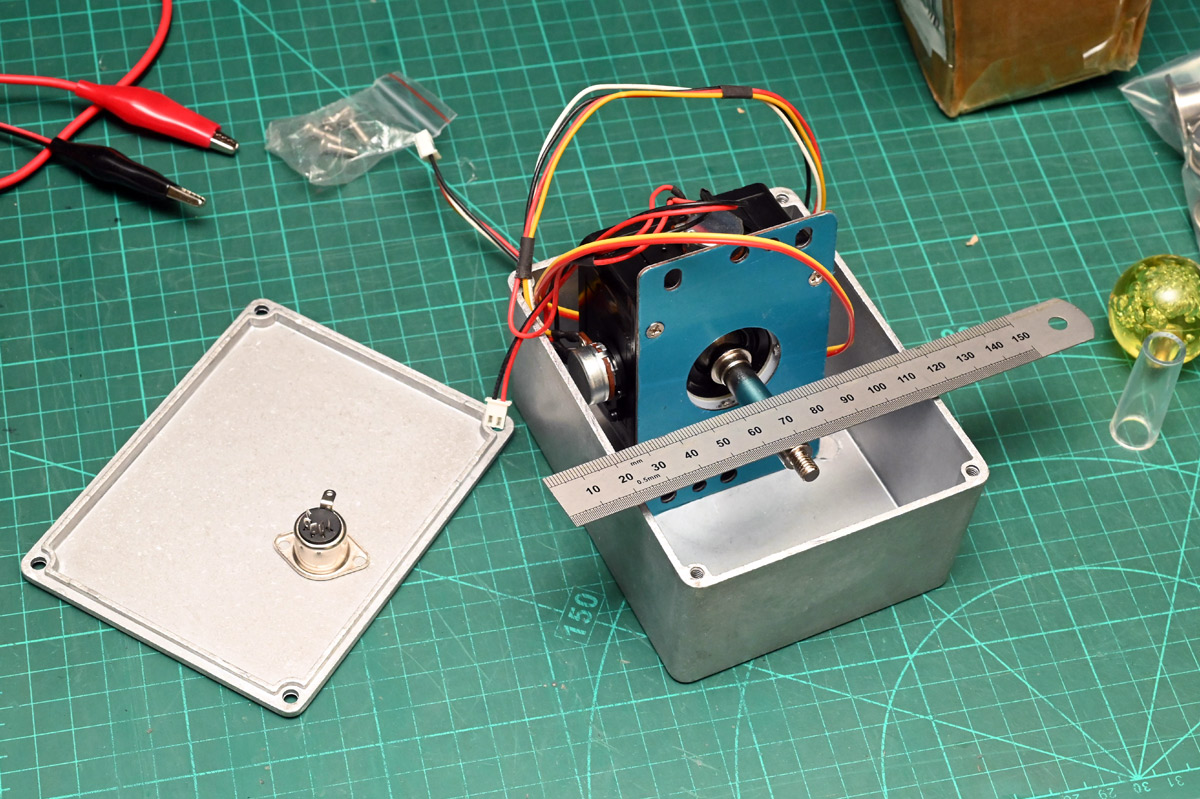
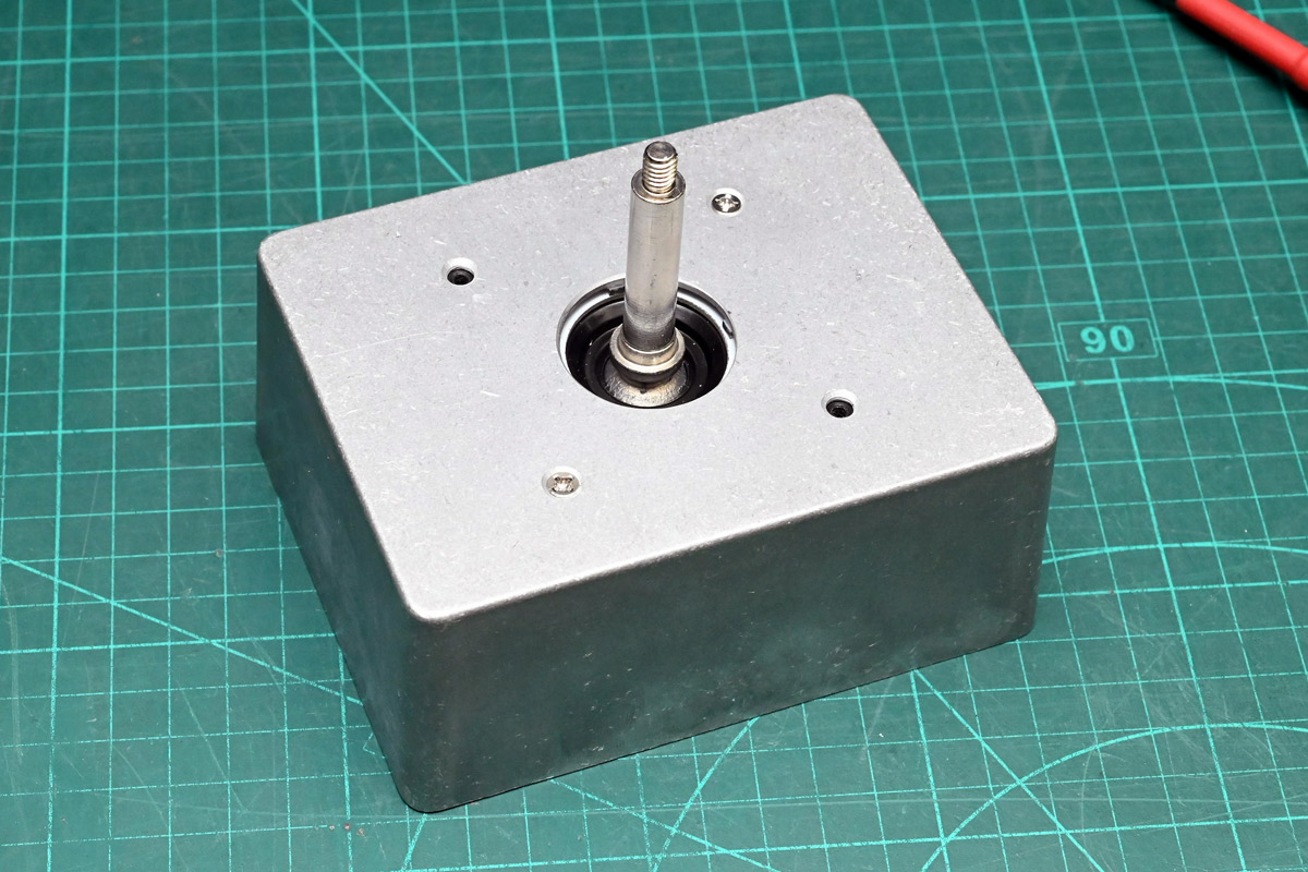
First thing is to mount the stick in the enclosure. The provided mounting plate was used to transfer the holes, which we then hit with the step drill.
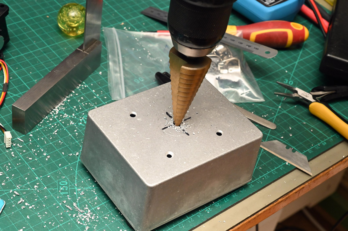
Scribe lines are faint but we can check progress with the mounting plate again.
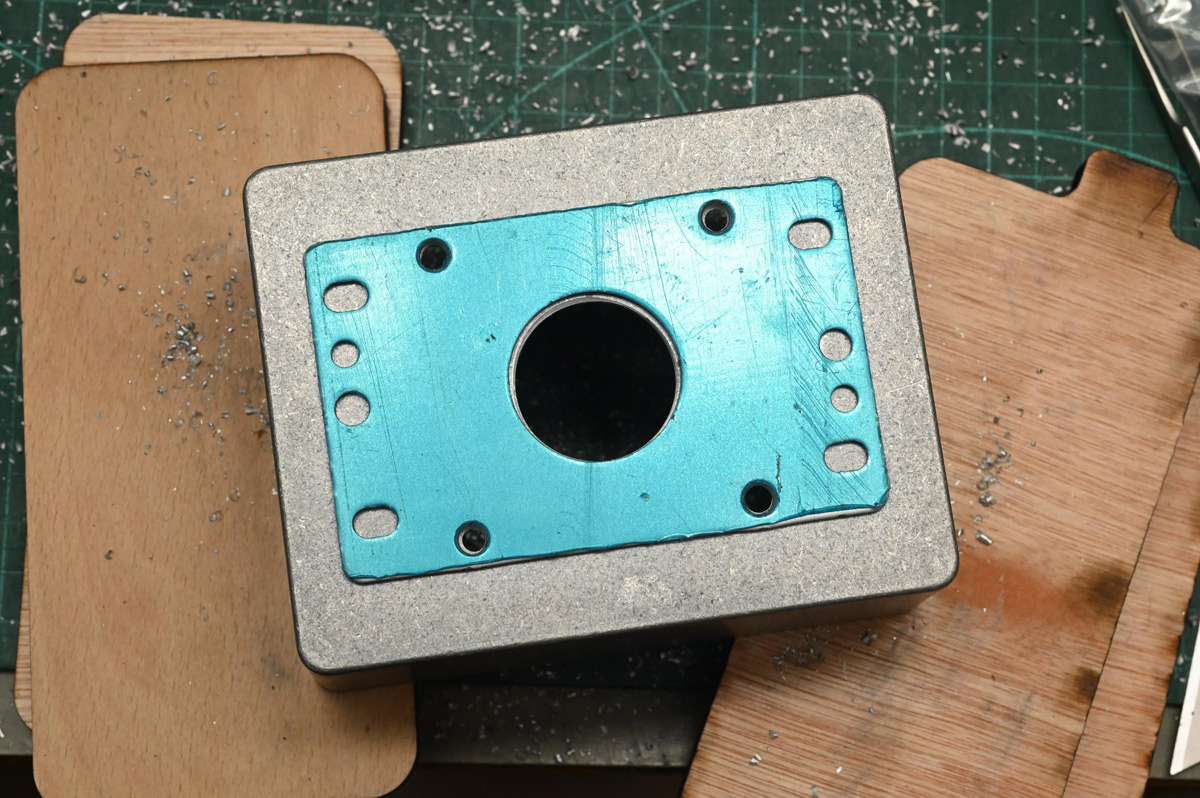
It's unclear if this plate is meant to sit underneath the mounted surface, or if we can forget it. A test fit shows the full range of motion, so we move on.
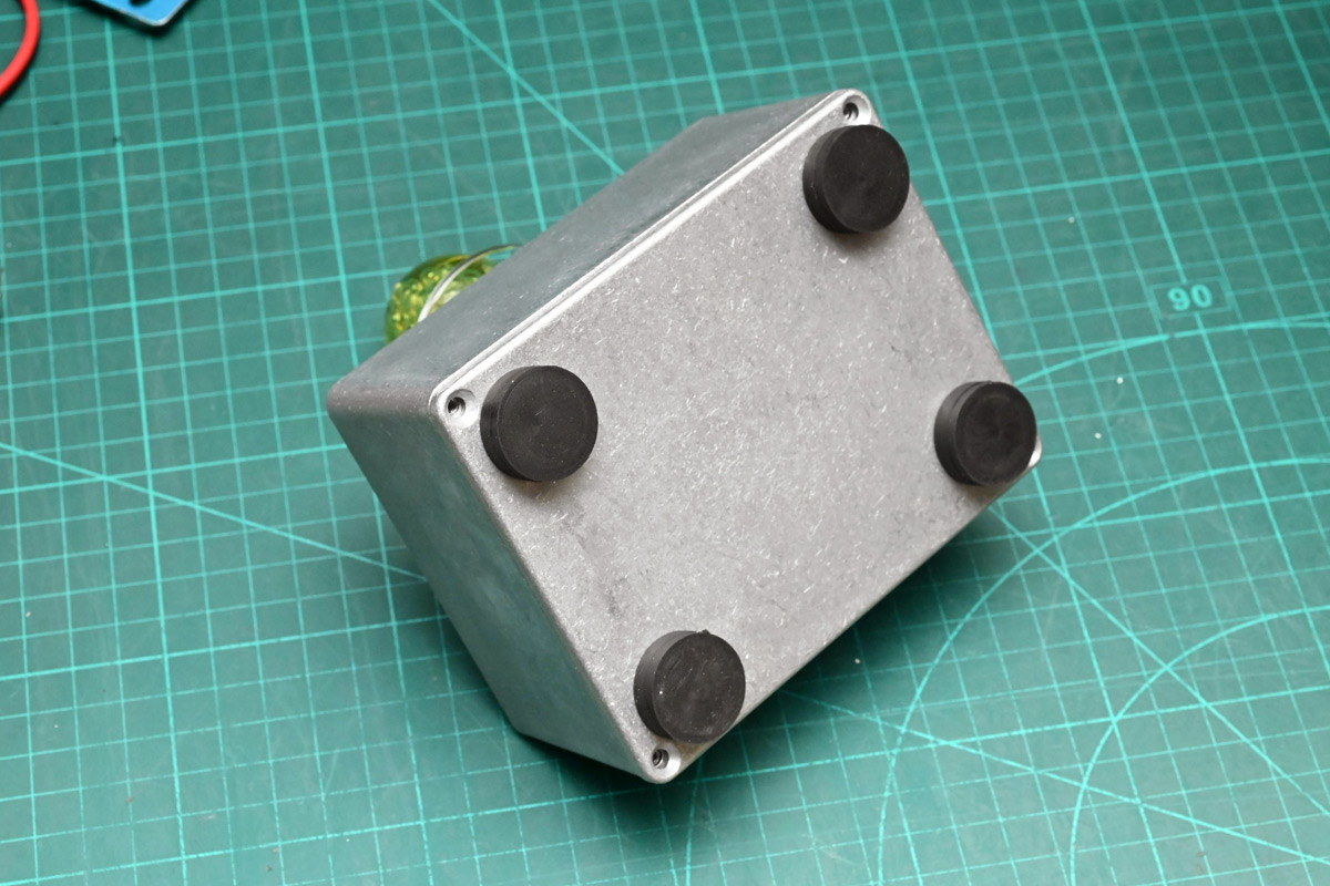
The underside gets a hole pattern for some rubber-coated magnets. I hadn't decided on how to make the pedestal, but magnets keep our options open.
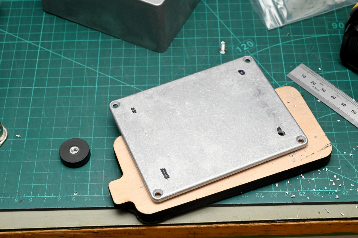
Convenient we have all these scrap bits of plywood around eh?
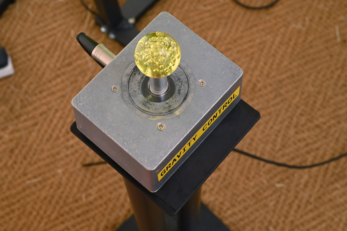
For connecting this to the motherboard, instead of a cable gland I had the idea to use a MIDI cable and a 5-pin DIN connector. They're cheap, available, and shielded. We can also get nice cables with industrial-looking metal plugs.
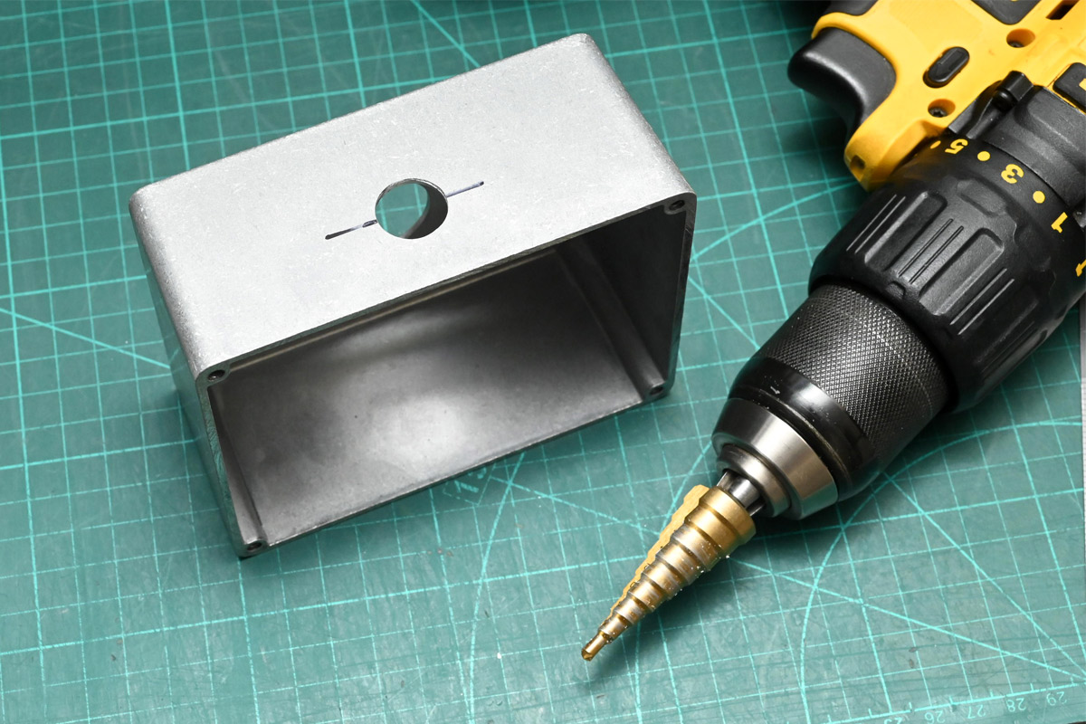
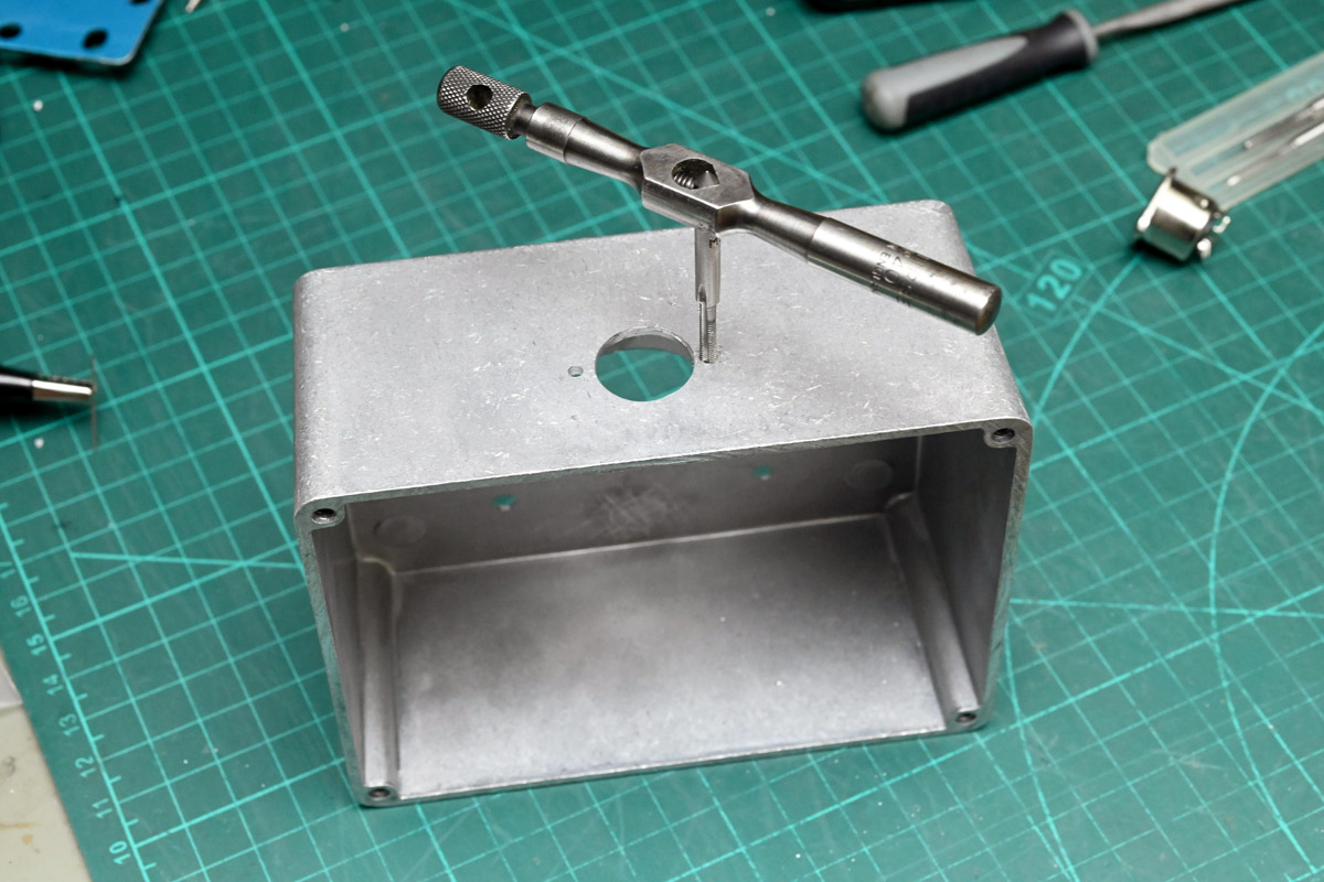
Out comes the little M3 tap wrench.
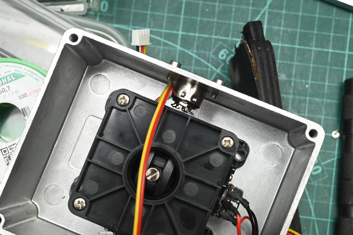
With the socket pins bent, there is just enough room for the joystick to be centred, almost as if we planned this.
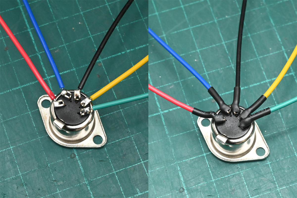
We then solder and heatshrink some wires to it.
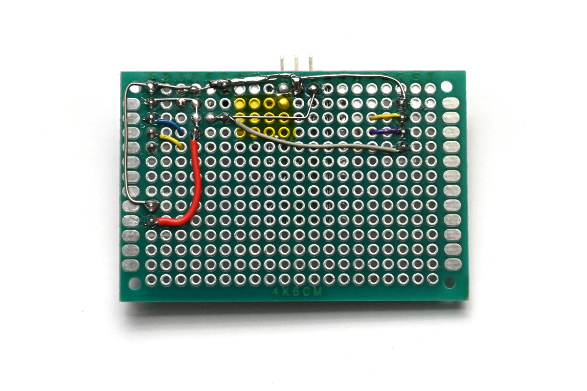
It would not be enough to wire the joystick to this connector and call it done. Noise and cable losses would ruin it. The plan was always to stick a microcontroller in here, which will read the joystick and transmit the digitised values. I couldn't start on this until the joystick was in my hands, right at the last moment, so this was cobbled together on protoboard.
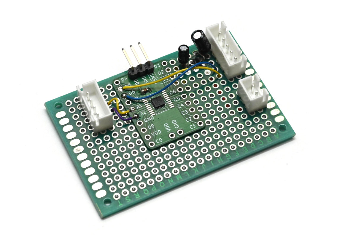
The joystick has JST XH connectors so I used one for the DIN connector too. We'll send 5V down the cable, then linear regulate that to 3V to provide a nice stable reference for the potentiometers. The regulator is a tiny SOT23 part in the corner. Another CH32V003 dev board uses its ADC to read the values when one of its pins is pulled low, and then transmits the raw numbers over UART (at, say, 31250 baud...?). We'll need a deadzone but that can be set on the motherboard. The 2-pin connector is for the LEDs on the joystick.
If you're interested in the dual-footprint dev board for the CH32V003 the design files are here.
The underside:
This gets a strip of velcro for a removable attachment inside the enclosure. Overall a pretty neat job eh?
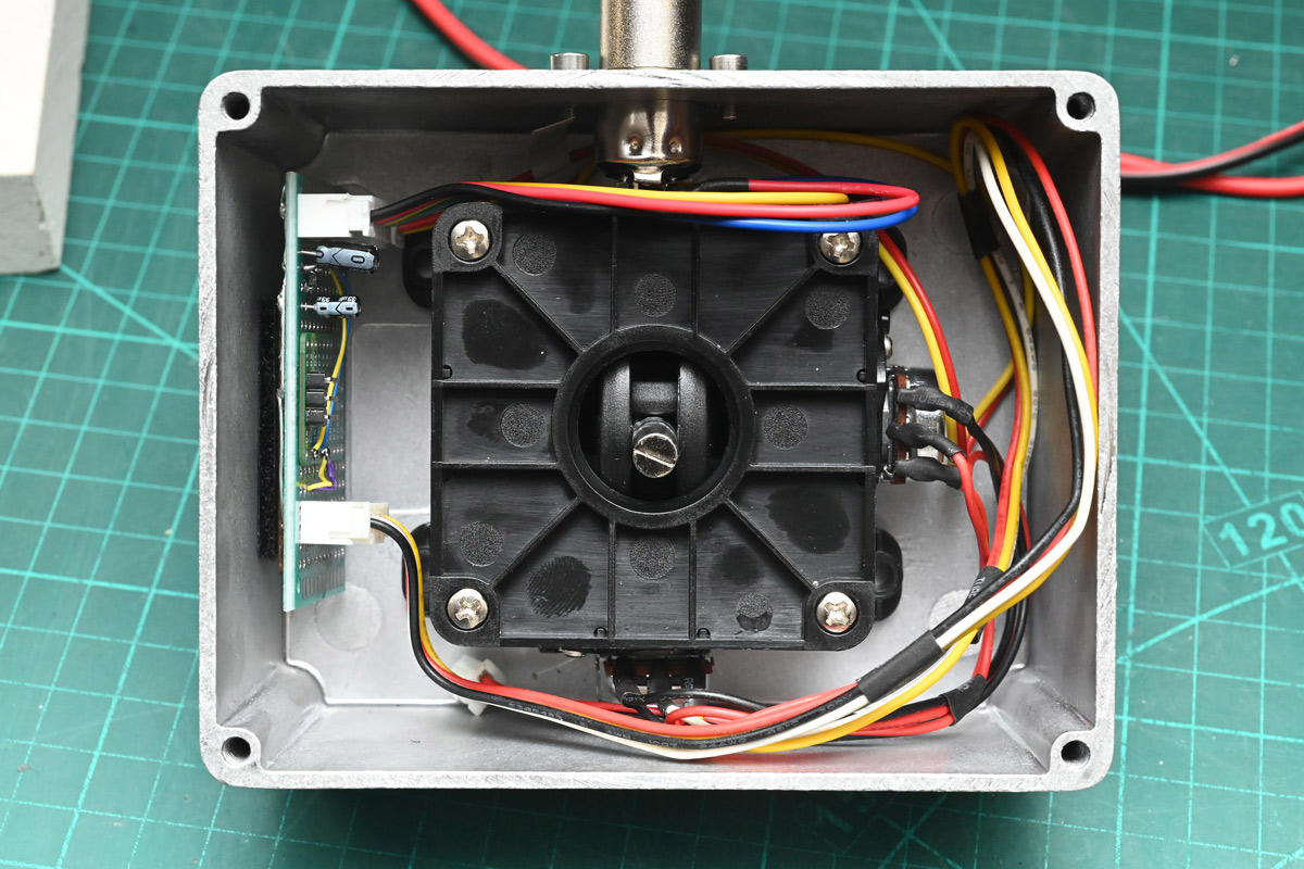
While the software on that micro is trivial, there's still something thrilling about writing it without testing, sealing up the box and hoping for the best.
Motherboard and power bus
At the heart of the installation is an STM32H7R3, a chip I've used a lot lately even if I've not published much with it. Don't be fooled by the H7 badge, that's just a marketing thing, the H7R3/H7S3 are kind of a different family to the others. All that matters is it's very fast, reasonably cheap, has a smidgen of onboard flash and is available in TQFP so we have a hope of soldering it ourselves. Base clock speed is 600MHz, and the only supporting parts we need are a few capacitors.One thing I've learned is to always break out the BOOT0 pin. The memory protection stuff on these chips is aggressive, even when it's supposedly disabled, and the slightest problem causes it to lock down the debug interface for security, effectively bricking the chip until you use the system loader to restore it. This has caught me out so many times it's worth installing a switch on the BOOT0 line. The rest of the board is simple, just a 3.3V regulator, the MAX485 to transmit to the panels, and a secondary UART to talk to the joystick. Instead of linear regulating directly from 12V, I stuck a buck converter on the board, but rather than do it with discrete components, it's much faster to grab a ready-made step-down module.
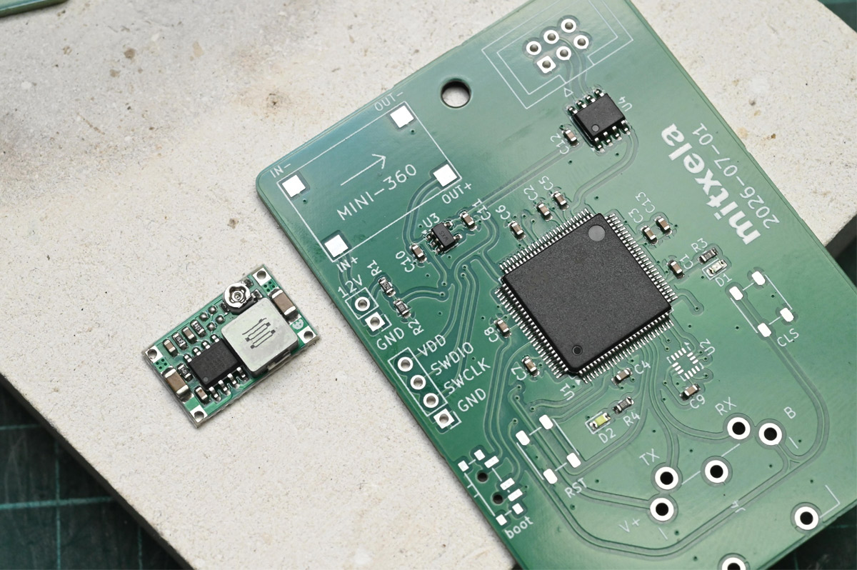
We set the trimpot to 5V before we soldered it down.
Finally there's some LEDs and, just in case we need it, an accelerometer (U2). I wish you could get them in bigger footprints, LGA is a right pain to solder.
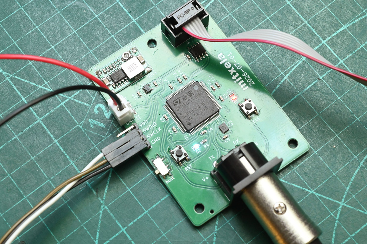
Until now, we'd been testing the panel in chunks with a USB-RS485 adapter. Before full scale testing we need to sort out the power distribution. Instead of a big busbar it was quickest to use wagos. Velcro will keep them tidy.
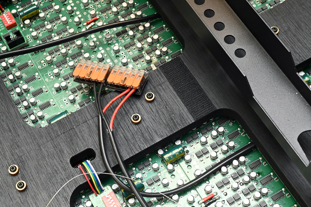
Apparently you can get a 10-way wago now, but 5-way is all I had, so we'll do two groups. This will also help if we need to split the power into separate domains later.
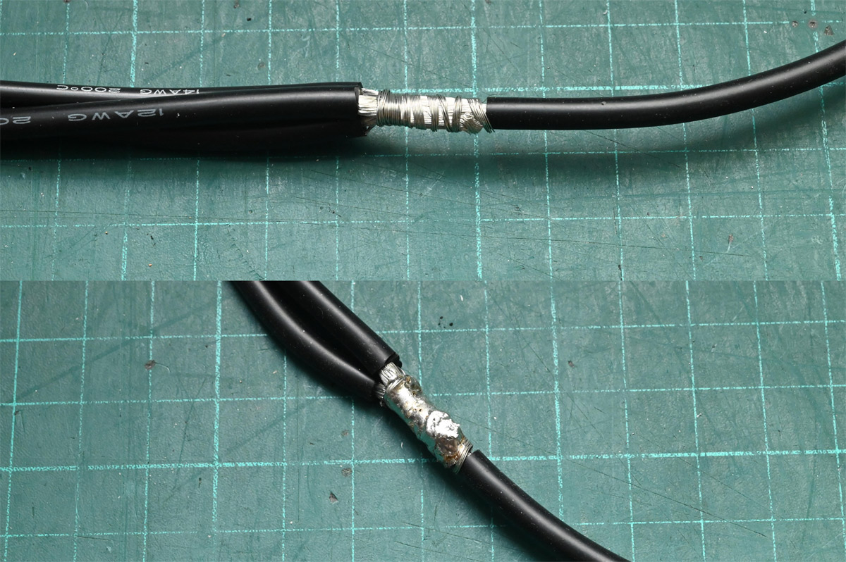
I made some three-way splitter cables to direct power to the groups and also bleed off for the motherboard. The trick is to smoosh the wires together, wrap tightly in more wire, paint it with flux and then flood it with solder. I used two irons simultaneously to give it enough heat.
Meanwhile the motherboard got a backing of EVA foam and was screwed into place. There's motivation to get the accelerometer centred on the panel, or we'll get spurious readings when the panel is rotated. Not that I expect the panel to see much spinning.
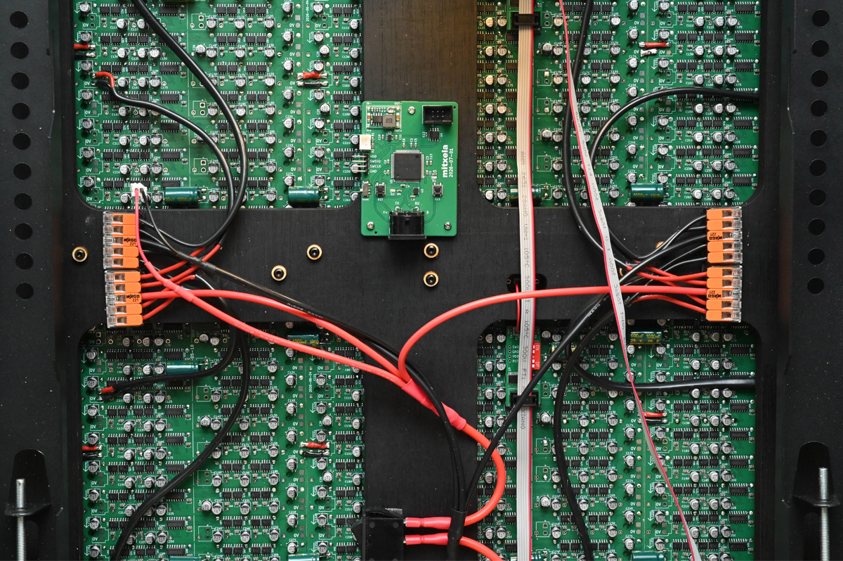
If the pace were more sedate I'd have stuck a polyfuse on the cable where the gauge changes (the loose motherboard connector on the left in the image above). I think it's fine, if a serious fault develops on the motherboard, that short bit of wire will probably burn itself out as a poor man's fuse.
Running first from our insane LiPos, and then from our customised power brick, the first full test patterns flipped to life. A nice thing about the DIP switches, we can give some panels the same ID for testing purposes.
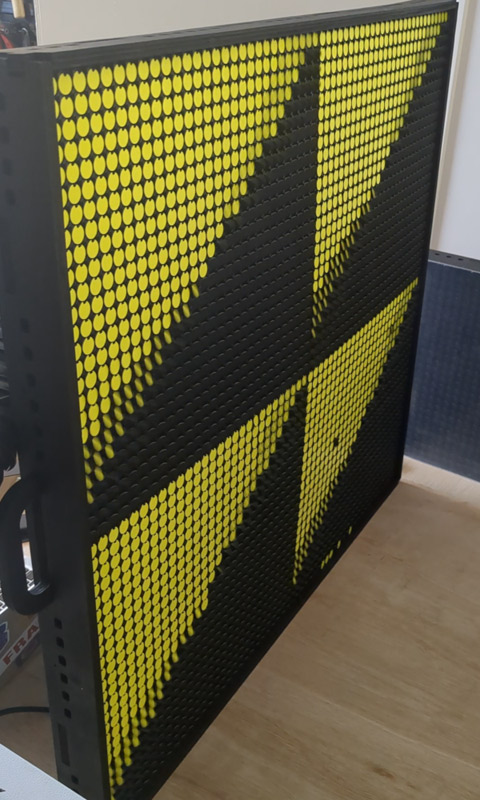
The next few hours were spent shooting test patterns out my laptop down the USB-RS485 adapter and figuring how our bits should be mangled. The pixel mapping would have been so much simpler if the panels had even one dimension divisible by eight.
A handful of newly dead pixels arose. A bunch of dots were stuck along the bottom edge simply by getting caught on the frame, I should have given a few mm more tolerance. Others failed for more complex reasons, but the first concern is whether power distribution is safe under maximum flippage.
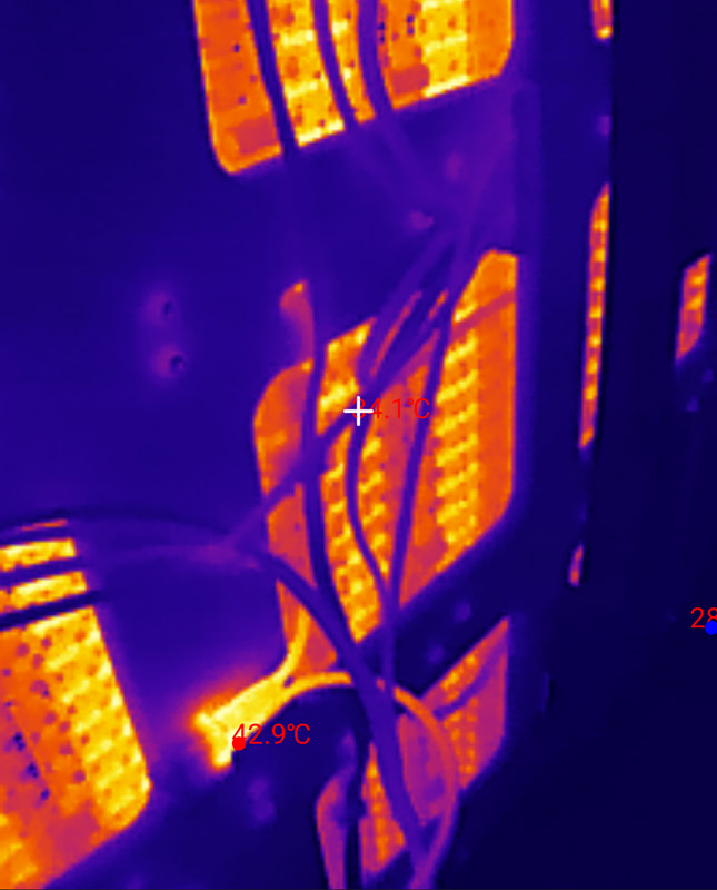
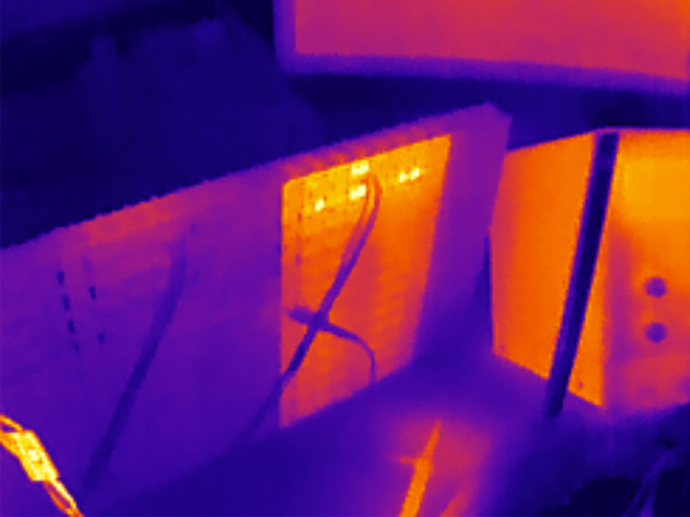
Man I love wagos. They're still at ambient temperature, you can barely make them out in the thermal image. To be fair they're only taking half the load. The soldered joints too are at room temperature. In contrast the spade terminals on the power switch are 43°C, and I don't think that's the switch contacts, that's the actual spade terminals being resistive. The XT60 connector is also warmer than I'd like, though we're nowhere near its current rating.
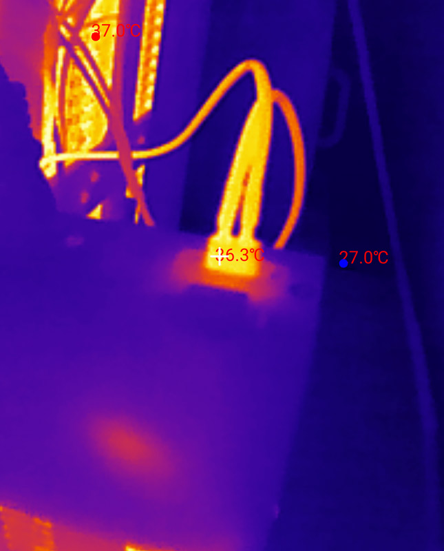
We plugged in the motherboard, and the LDO gets hot, but less hot than if it were dropping from 12V.
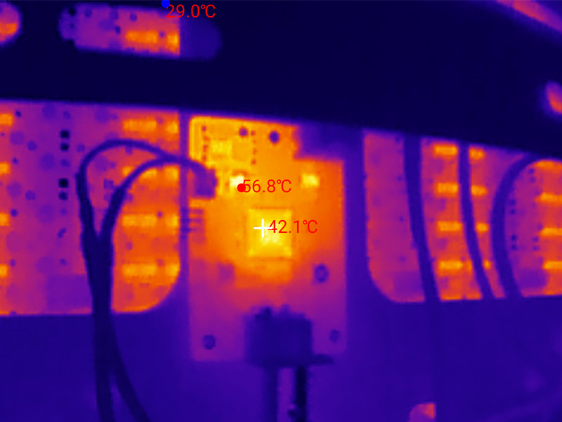
Once the pixel mapping was established, coaxing the motherboard to talk to the panel was gruntwork. Our fluid sim has already been ported to this chip, so the only remaining task was to read the joystick. Delightfully, all was well, we even avoided the traditional mistake of swapping RX and TX.
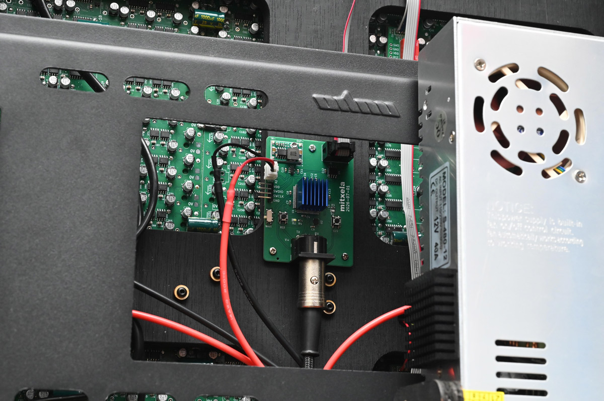
Finally I chucked a baby heatsink on the processor, shown here with the panel now mounted to the stand:
Supported by the stand, we slightly loosened the frame and the dead pixels on the bottom row came back to life. Some of the pixels were properly dead though. With very little time remaining, I made the dubious decision to dismantle everything and investigate the problem. I expected soldering mistakes, but to my horror, near the standoffs on the last few panels we built, the coils themselves were damaged!
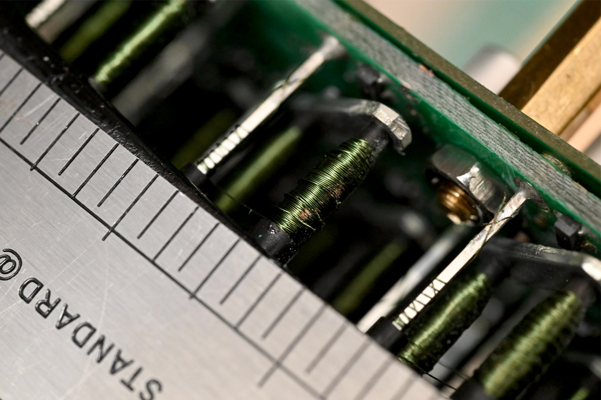
I must have been overconfident with the tweezers towards the monotonous end. Our options here are limited, we have spare parts, but desoldering the full group of seven with the double circuit board behind it is going to be dastardly difficult. I opted to repair the coils, gently unwinding them with tweezers, removing the broken sections, identifying the loose ends and soldering them together.
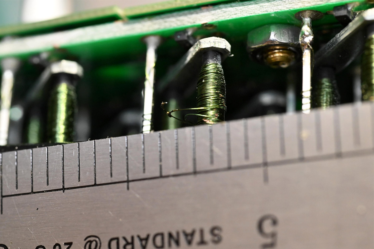
The coil may have lost a few turns but it still functions. Afterwards we wrapped this in paper to protect it from the sticky tape that normally lines the panel, then tested and reassembled.
One of the fiddliest bits of soldering I've done in a long time. I then repeated this repair four times.
Is our flipdot display finished?
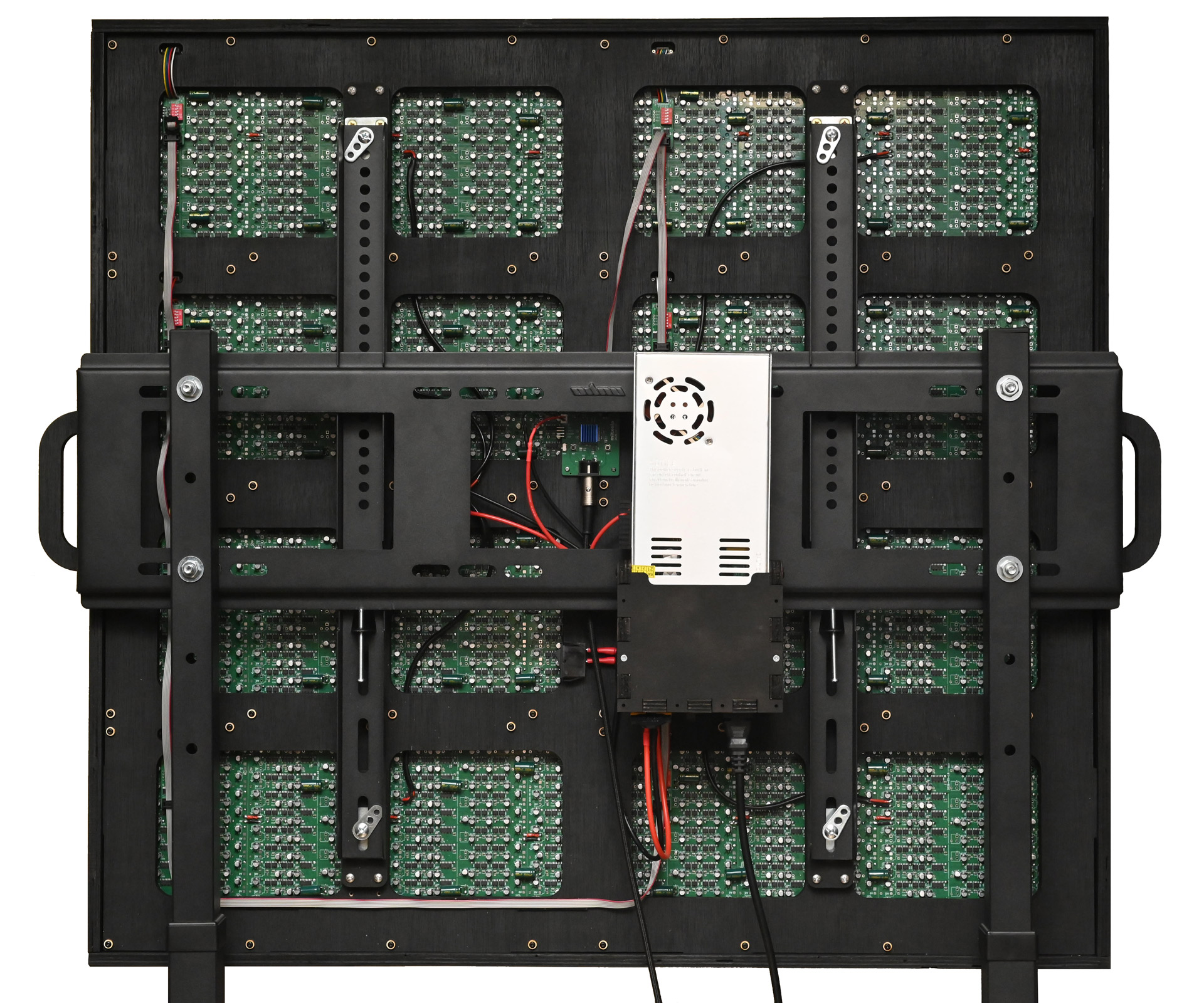
Logo
It's important! We can't skip putting a pretty sign on it. I laser cut a design once in 3mm plywood, painted black, and once in 5mm painted silver.
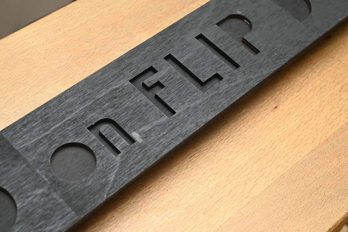
The silver positives were glued into the black negatives, with the whole thing mounted on brackets velcro'd in place.

And in case anyone wonders what the joystick is for, a nicely laminated label sets things straight.
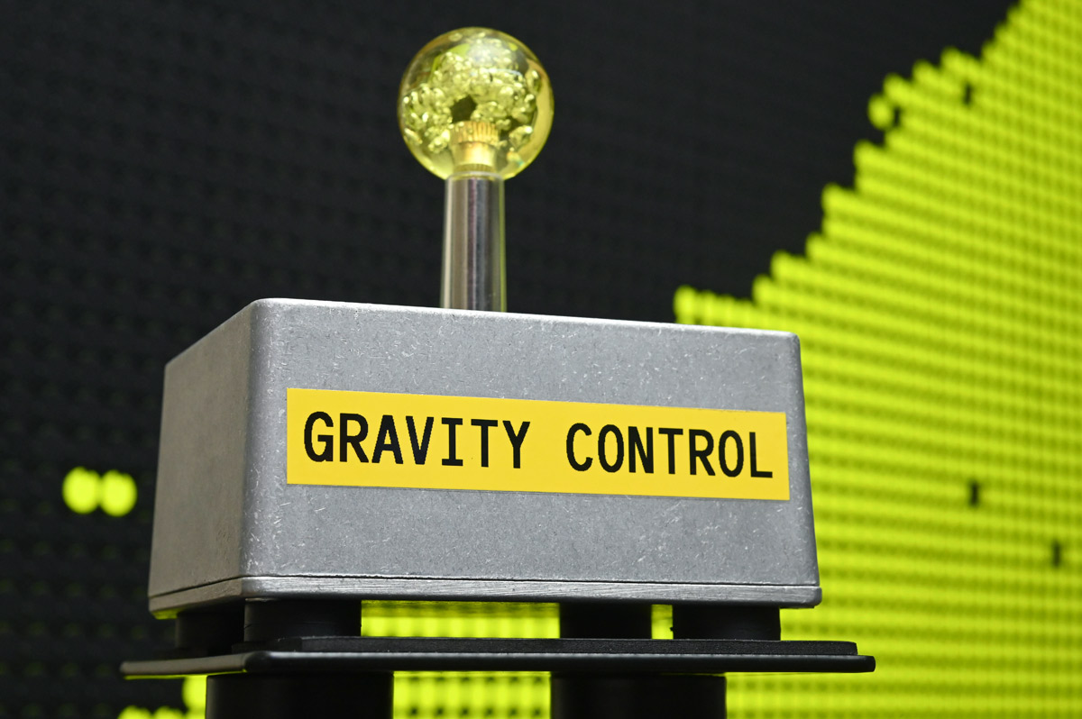
A slightly overpriced industrial-looking "speaker stand" serves as the pedestal.
The Event
Chatting with the Arts team, it was quite hard to decide where the flipdots should go. A lot of the interactive art ends up in Null Sector (a kind of cyberpunk rave area built from shipping containers) or the bar, or the arcade, all of which are such noisy environments we wouldn't be able to enjoy the flipping noise. I was offered a dedicated half-dome, but the weather forecast predicted thunderstorms with torrential rain and I was worried the dots would be too exposed.About the only place guaranteed to be quiet was the "lounge" tent, where noisy exhibits are outlawed. Not everyone was pleased about me setting up there, but it was hard to judge until the thing was turned on. I figured I'd set up and if it's deemed too loud we'll move it elsewhere. First task was to level the feet and secure it with these 10" pegs.
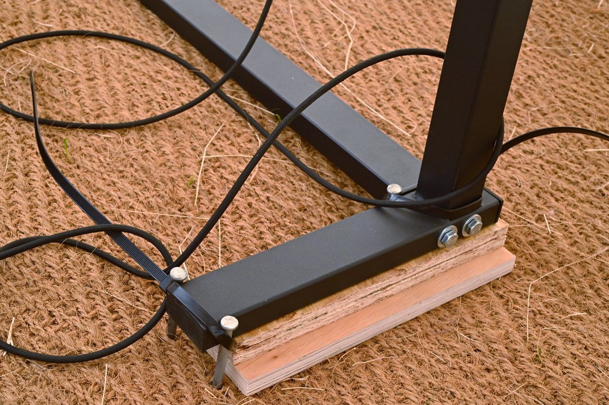
I wrapped the (extra long) joystick cable around the legs to reduce the chance of it yanking the thing over.
Ultimately the weather turned out swelteringly hot and dry. So hot that I had a genuine concern the thing would catch fire. To my delight, on the first day someone donated a pile of old server fans to the EMF swap shop! I chose the quietest of them and rigged them to the back, shown here after they'd been running for a few days, hence the dust:
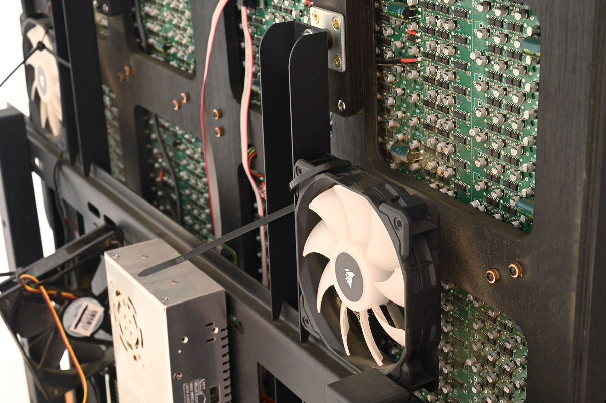
Even the adjustable power supply driving the fans came from the swap shop. In return, I donated a bunch of soldering equipment that got gobbled up right away.
The installation ran without fault for the full four days of the event. A bunch of dead pixels appeared, mostly from people poking it I think, or just dust and dirt jamming it.
I was able to walk away, to see the rest of the festival and worry about my talk, and almost every time I returned people were playing with it.

Early morning or late at night, where the joystick was untouched for an hour or more, it would spread out into these patterns with the fluid in zero gravity. I left the viscosity at zero, so the only way for the fluid to lose energy was by colliding with the walls. It takes a long time to settle.
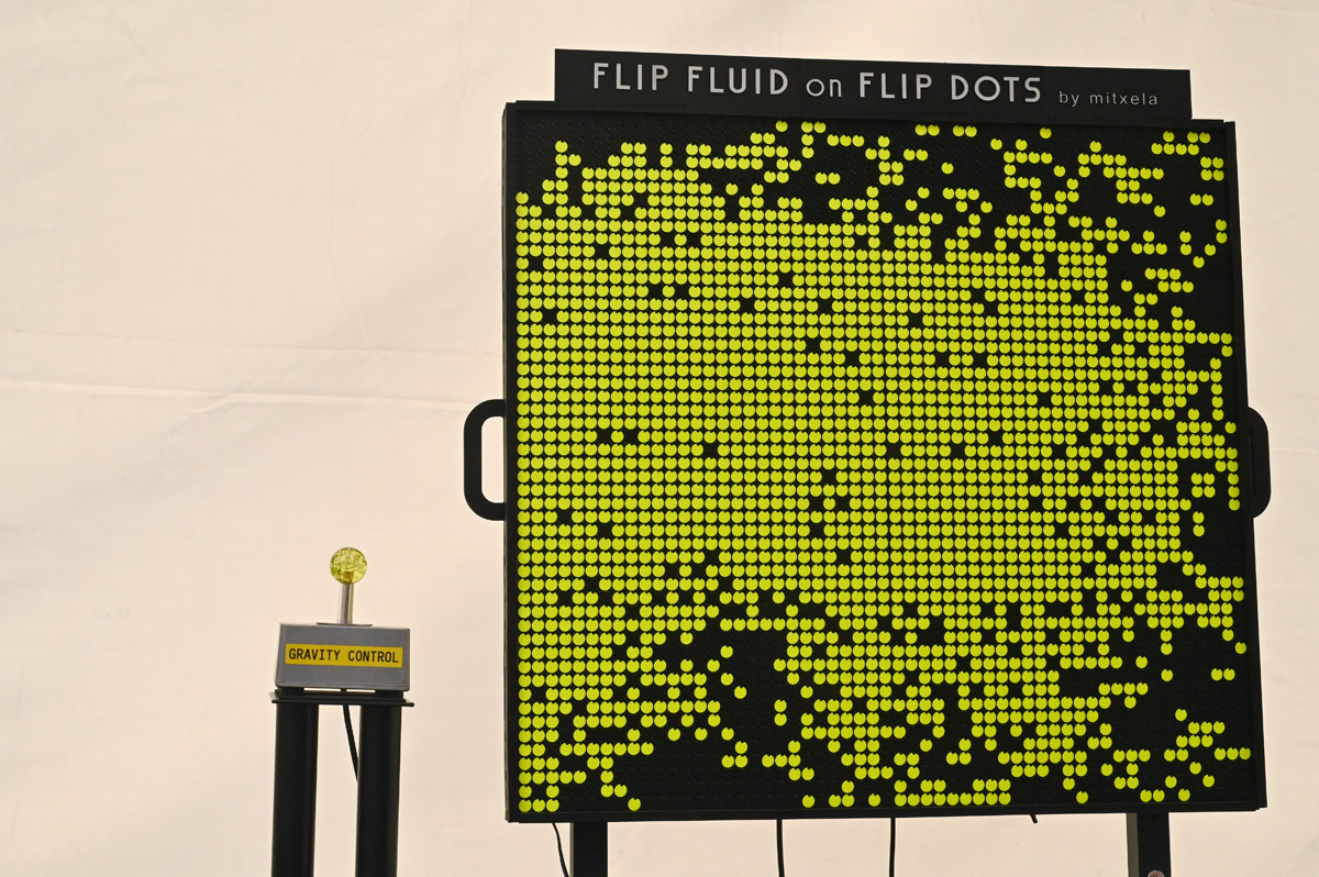
The joystick saw so much use that a grimy wear pattern appeared. Additionally, by the end of the event the screws on the underside of the enclosure had loosened. It might have been some kind of precession effect, where people spinning the joystick in one direction caused the screws to unwind.
I regret not making a plaque explaining the pun and how the flipdots work. I did write a blurb but it never got printed out as the Arts team were somewhat overwhelmed. EMF is extremely popular, tickets sold out almost immediately, and one of the only ways to guarantee a ticket as a newcomer is to have an artwork or talk accepted. This year there were more proposals (and acceptances!) than ever before.
EMF is a magical place, it's one of the rare situations in the UK where people can be whoever they want to be, without fear of being judged. You can be as weird as you like, and apparently, what I wanted to be, was someone taking their flipdots for a walk.
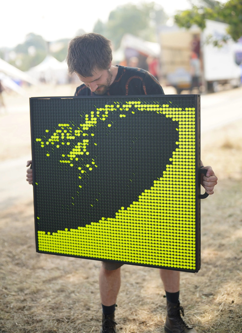
I hadn't abandoned my gimbal dreams though. Remember that last idea to use a big squishy ball? It wouldn't be perfect, but when I realised how cheap and easy it was to try, I was sold.
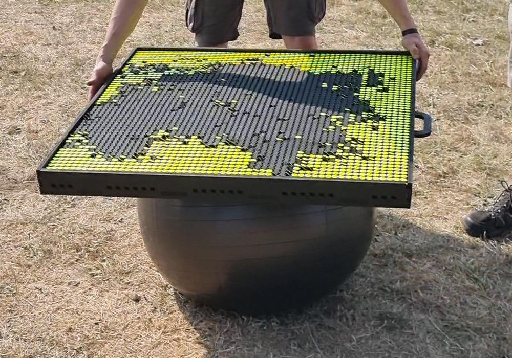
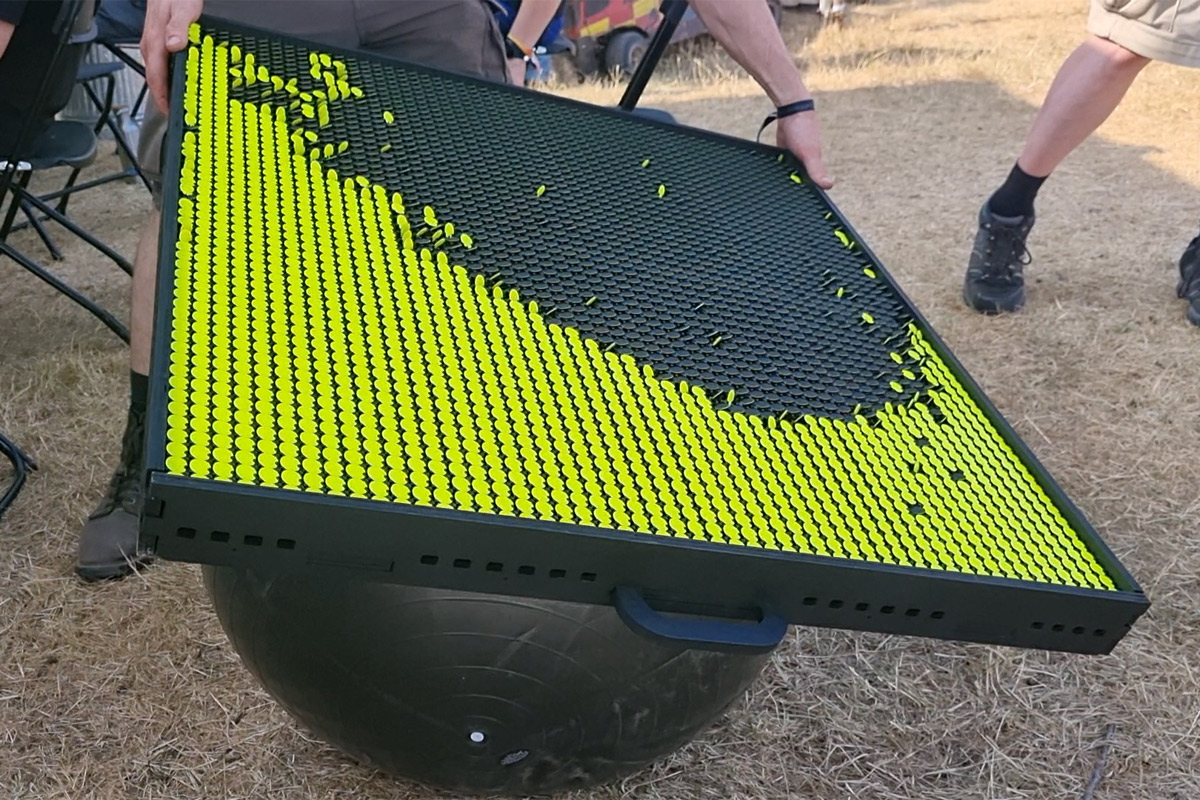
The fact that inflatable exercise balls are referred to as a "Gym ball" was icing on the cake. Gymball gimbal!
Conclusion
The length of this writeup conveys only a fraction of the tedium in all that soldering.The total cost for the big panel, not including the donor parts or my time, was under £500, or around £0.17 per dot. If you factor in my time, well... it's clear why the commercial offerings will run you five or six figures.
If you happen to have a 13x28 Hanover flipdot display, I've put my PCB designs for driving them up on github. Sam has a load more panels in storage, but they're all different sizes, so the next step is to adapt the design, and then convince some volunteers to do all the soldering for us.
As for this panel, I have a few ideas. Since they're non-volatile, it would have been great to build the circuitry in a way that could read out the state of a dot. We could use the panels as core-memory with visible state. Or we could turn the panel into any number of video games, I'm sure Tetris or Snake would be great fun. A flipdot arcade machine.
I have another idea I think would be great, but I'll keep it a surprise until it's posted, hopefully soon.